EP0352579A1 - Trigger action coupling lever for multipolar connectors - Google Patents
Trigger action coupling lever for multipolar connectors Download PDFInfo
- Publication number
- EP0352579A1 EP0352579A1 EP89113022A EP89113022A EP0352579A1 EP 0352579 A1 EP0352579 A1 EP 0352579A1 EP 89113022 A EP89113022 A EP 89113022A EP 89113022 A EP89113022 A EP 89113022A EP 0352579 A1 EP0352579 A1 EP 0352579A1
- Authority
- EP
- European Patent Office
- Prior art keywords
- lever
- socket
- plate
- springs
- lever according
- Prior art date
- Legal status (The legal status is an assumption and is not a legal conclusion. Google has not performed a legal analysis and makes no representation as to the accuracy of the status listed.)
- Withdrawn
Links
- 230000008878 coupling Effects 0.000 title claims description 12
- 238000010168 coupling process Methods 0.000 title claims description 12
- 238000005859 coupling reaction Methods 0.000 title claims description 12
- 210000005069 ears Anatomy 0.000 claims abstract description 4
- 230000000694 effects Effects 0.000 description 1
- 238000003780 insertion Methods 0.000 description 1
- 230000037431 insertion Effects 0.000 description 1
- 238000004519 manufacturing process Methods 0.000 description 1
- 238000000034 method Methods 0.000 description 1
Images
Classifications
-
- H—ELECTRICITY
- H01—ELECTRIC ELEMENTS
- H01R—ELECTRICALLY-CONDUCTIVE CONNECTIONS; STRUCTURAL ASSOCIATIONS OF A PLURALITY OF MUTUALLY-INSULATED ELECTRICAL CONNECTING ELEMENTS; COUPLING DEVICES; CURRENT COLLECTORS
- H01R13/00—Details of coupling devices of the kinds covered by groups H01R12/70 or H01R24/00 - H01R33/00
- H01R13/62—Means for facilitating engagement or disengagement of coupling parts or for holding them in engagement
- H01R13/627—Snap or like fastening
- H01R13/6275—Latching arms not integral with the housing
Definitions
- This invention relates to the devices coupling plug and socket in multipolar connectors.
- Assembly of the said coupling levers is performed in the following way: the lever is moved towards the socket, making its holes coincide with the holes on the socket; one pin is inserted, making it enter the accessible one of the two holes on the lever and the socket, after having inserted a spring, consisting of a shaped metallic wire, between the lever and the head of the pin. Finally the head of the pin is riveted to make the connection irremovable.
- the socket is rotated 180 degrees to give access to the other two holes on the socket and the lever, and the assembly process is repeated for the second extremity on the lever.
- Aim of the present invention is therefore the production of a coupling device which is simple, sturdy and economical, and which allows the use of automatic assembling equipment.
- a trigger action coupling lever for multipolar sockets comprising two elastic side elements, identical with each other, rotatably mounted on the socket, each one being connected to a side plate, the said plates being joined to a connecting crosspiece.
- each elastic side element is made with two identical springs coupled together, locking said plate between them.
- the extremity of the lever which makes contact with the pin provided on the plug is equipped with an idle roller.
- One preferred solution provides an extension of the plate so as to form a limit stop for the movement of the lever.
- the springs are flat and semicircular ring shaped.
- the spring can widen at its extremities into two drilled ears and have a semicircular drilled projection on its intermediate portion for fixing it to the plate.
- the crosspiece can be equipped with a name plate holder tab.
- Figure 1 shows a connector with a multipolar plug 5, connected to an electric cable C.
- the plug S is inserted into the corresponding socket P out of which comes a second electric cable C′.
- the plug S and the socket P are locked by means of coupling levers 1, the subject of the present invention, which rotate around the pin 4, which is integral with the socket P, and engage on the coupling pins A, being integral with the plug S.
- the proposed lever 1 comprises (figure 2) a shaped metallic side plate 2 with a circular hole 3 for inserting the pin 4 for fastening it to the socket, and with further holes, 5 and 6 respectively, the first of which serves for fastening the crosspiece and the second for fastening the spring 7.
- the hole 5 is located on a shaped extremity 2b which can be received into a notch 17 provided on the crosspiece 11, as will be explained later.
- the plate 2 also provides a ledge 2a which causes the lever to stop against the pin A.
- a metallic spring 7 in the shape of a flat semicircular ring can be seen, which widens at its extremities into two ears, 8 and 9 respectively, each of which has a circula through hole. On its intermediary portion, the spring 7 has a semicircular projection with a circular through hole 10.
- Figure 4 shows a roller 15, equipped with two pins 16 consistuting the hubs of said roller.
- Figure 5 shows a crosspiece 11, which can be made of plastic material, comprising a bar 12 from which two arms 13a and 13b extend perpendicularly.
- a hub 12a provided on the bar 12 can be used as connector identification plate holder.
- the arms 13a and 13b are each crossed by a rectangular sectioned notch 17 for receiving the extremity 2b of the plate 2.
- a circular sectioned projection 14 capable of being received into the hole 5 at the extremity 2b of the plate 2.
- This projection will represent the means for locking the crosspiece 11 to the plate 2.
- one wall 14a of the projection 14 is made sloping so as to form a guide when the crossplate is introduced onto the plate 2.
- a pair of coupling levers 1 is carried out as follows: a side plate 2 and a roller 15 are taken and made integral with two springs 7 positioned one on one side and one on the other side of the plate 2 and of the roller 15.
- Figure 6 shows the side plate 2 on which the two springs 7 have been inserted, one on one side and one on the other; only one of the springs is visible.
- the springs 7 are locked against the plate 2 by riveting the pins 16 of the roller 15, which is mounted idle in the holes 3 of the springs 7.
- a rivet 21 is introduced and riveted into the hole 6 on the side plate 2 which has come into a corresponding position with the hole 10 on the spring 7.
- the hole 9 on the spring is now placed over the hole 3.
- the units thus formed are then brought close to the socket P to correspond with the two coaxial holes provided on the opposite sides of the socket; next the two locking pins 4 are inserted and then riveted.
- the crosspiece 11 is then brought close to the socket P and the arms 13a and 13b of the crosspiece 11 are inserted into the two extremities 2a of the side plates 2.
- the projections 14 will make the crosspiece integral with the plates 2.
Landscapes
- Details Of Connecting Devices For Male And Female Coupling (AREA)
Abstract
The proposed device preferably comprises two pairs of springs (7), identical with each other, mounted on a respective side plate (2), which is made integral with a connecting crosspiece (11), having a tab (12a) which can be used as a name plate holder.
The springs (7) act on the locking stop (A) by means of an idle roller (15).
In addition, the springs (7) are in the shape of a flat semicircular ring, widening at its extremities into two ears, each having a hole (8, 9). In addition, each spring (7) has on its intermediate portion a semicircular projection which is also provided with a hole (10).
Description
- This invention relates to the devices coupling plug and socket in multipolar connectors.
- After a plug, connected to a multipolar electric cable, is inserted into the corresponding socket, it is necessary to effect the locking between plug and socket which can prevent the accidental withdrawal of the plug in the case of traction of the electric cable.
- Devices are already known providing such locking; their working principle is based on a pair of trigger action levers mounted astride of the shorter sides of the multipolar socket and capable of rotating around the pin connecting them to the socket. Each of the said levers has a pair of facing notches which, when rotated, snap into position onto the corresponding pins provided on the body of the multipolar socket. Normally, such levers are made of a single piece of plate and have a pair of holes aligned for insertion of the hinge pin to the socket.
- Assembly of the said coupling levers is performed in the following way: the lever is moved towards the socket, making its holes coincide with the holes on the socket; one pin is inserted, making it enter the accessible one of the two holes on the lever and the socket, after having inserted a spring, consisting of a shaped metallic wire, between the lever and the head of the pin. Finally the head of the pin is riveted to make the connection irremovable. When this operation is completed, the socket is rotated 180 degrees to give access to the other two holes on the socket and the lever, and the assembly process is repeated for the second extremity on the lever.
- The device described shows some drawbacks, such as:
- a) the springs to be inserted between the lever and the pin are of the right hand and left hand types, that is they are symmetrical, one with the other, but not equal; this makes it necessary to have two series of springs available, complicating assembly and increasing storage costs;
- b) to assemble the lever onto the multiplar socket it is necessary to rotate the socket which makes the possibility of mechanized assembly difficult and expensive.
- Aim of the present invention is therefore the production of a coupling device which is simple, sturdy and economical, and which allows the use of automatic assembling equipment.
- Said aim has been reached by producing a trigger action coupling lever for multipolar sockets comprising two elastic side elements, identical with each other, rotatably mounted on the socket, each one being connected to a side plate, the said plates being joined to a connecting crosspiece.
- In a preferred embodiment, each elastic side element is made with two identical springs coupled together, locking said plate between them.
- Preferably, the extremity of the lever which makes contact with the pin provided on the plug is equipped with an idle roller.
- One preferred solution provides an extension of the plate so as to form a limit stop for the movement of the lever.
- In another preferred embodiment, the springs are flat and semicircular ring shaped.
- In this case the spring can widen at its extremities into two drilled ears and have a semicircular drilled projection on its intermediate portion for fixing it to the plate.
- Finally, the crosspiece can be equipped with a name plate holder tab.
- A preferred embodiment of this invention will now be described, with reference to the enclosed drawings, in which:
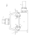
- Fig. 1 shows an overall shematic side view of the coupling lever which is the subject of the present invention, mounted on a multipolar socket;
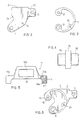
- Fig. 2 shows a side view of a plate making up part of the lever which is the subject of the present invention;
- Fig. 3 shows a side view of one of the springs making up part of the lever which is the subject of this invention;
- Fig. 4 shows a side view of a spring roller making up part of the lever which is the subject of the present invention;
- Fig. 5 shows a top view of a crosspiece making up part of the lever which is the subject of the present invention;
- Fig. 6 shows a side view of the spring in figure 3 after mounting on the side plate in fig. 2.
- Figure 1 shows a connector with a multipolar plug 5, connected to an electric cable C. The plug S is inserted into the corresponding socket P out of which comes a second electric cable C′. The plug S and the socket P are locked by means of coupling levers 1, the subject of the present invention, which rotate around the pin 4, which is integral with the socket P, and engage on the coupling pins A, being integral with the plug S.
- The proposed lever 1 comprises (figure 2) a shaped
metallic side plate 2 with acircular hole 3 for inserting the pin 4 for fastening it to the socket, and with further holes, 5 and 6 respectively, the first of which serves for fastening the crosspiece and the second for fastening thespring 7. The hole 5 is located on ashaped extremity 2b which can be received into anotch 17 provided on thecrosspiece 11, as will be explained later. Theplate 2 also provides a ledge 2a which causes the lever to stop against the pin A. - With reference to figure 3, a
metallic spring 7 in the shape of a flat semicircular ring can be seen, which widens at its extremities into two ears, 8 and 9 respectively, each of which has a circula through hole. On its intermediary portion, thespring 7 has a semicircular projection with a circular throughhole 10. - Figure 4 shows a
roller 15, equipped with twopins 16 consistuting the hubs of said roller. - Figure 5 shows a
crosspiece 11, which can be made of plastic material, comprising abar 12 from which twoarms hub 12a provided on thebar 12 can be used as connector identification plate holder. Thearms notch 17 for receiving theextremity 2b of theplate 2. Into thenotch 17 enters a circular sectionedprojection 14, capable of being received into the hole 5 at theextremity 2b of theplate 2. This projection will represent the means for locking thecrosspiece 11 to theplate 2. To facilitate the introduction of thecrosspiece 11 onto theplates 2, onewall 14a of theprojection 14 is made sloping so as to form a guide when the crossplate is introduced onto theplate 2. - The assembly of a pair of coupling levers 1 is carried out as follows: a
side plate 2 and aroller 15 are taken and made integral with twosprings 7 positioned one on one side and one on the other side of theplate 2 and of theroller 15. Figure 6 shows theside plate 2 on which the twosprings 7 have been inserted, one on one side and one on the other; only one of the springs is visible. Thesprings 7 are locked against theplate 2 by riveting thepins 16 of theroller 15, which is mounted idle in theholes 3 of thesprings 7. In addition arivet 21 is introduced and riveted into the hole 6 on theside plate 2 which has come into a corresponding position with thehole 10 on thespring 7. The hole 9 on the spring is now placed over thehole 3. The units thus formed are then brought close to the socket P to correspond with the two coaxial holes provided on the opposite sides of the socket; next the two locking pins 4 are inserted and then riveted. Thecrosspiece 11 is then brought close to the socket P and thearms crosspiece 11 are inserted into the twoextremities 2a of theside plates 2. Theprojections 14 will make the crosspiece integral with theplates 2. - To lock the plug to the socket it will be enough to operate the
crosspiece 11 to make the lever 1 rotate aorund the pins 4, until theside plates 2 engage on the locking pins A. This will take place by elastically stressing of the springs. To unlock the plug, the operation is repeated by rotating the lever 1 in the opposite direction. - It is clear how the invention described is capable of reaching the above-mentioned aims; in fact the
springs 7 and theplates 2 are of a type only, suitable for mounting on both sides of the socket. The coupling lever 1 can be assembled by automatic devices since the socket no longer needs to be rotated.
Claims (8)
1. A trigger action coupling lever for multipolar connectors, comprising a socket (P) equipped with a pin (4) around which the lever (1) rotates, and a plug (S), equipped with a coupling pin (A), characterized in that the lever (1) comprises two elastic elements (7), identical with each other, rotatably mounted on the socket (P), each one being connected to a side plate (2), the said plates being joined by a connecting crosspiece (11).
2. A lever according to claim 1, characterized in that each elastic element is made with two identical springs (7) coupled together, between which the plate (2) is inserted.
3. A lever according to claims 1 or 2, characterized in that the extremity of the lever (1) which makes contact with the pin (A) provided on the plug (S) is equipped with an idle roller.
4. A lever according to any one of the preceding claims, characterized in that the plate (2) extends in such a way as to form a ledge (2a) acting as a limit stop for the rotatory movement of the lever (1).
5. A lever according to any one of the preceding claims, characterized in that the springs (7) are in the shape of a flat semicircular ring.
6. A lever according to claim 5, characterized in that the spring (7) widens at its extremities into two ears having holes (8, 9).
7. A lever according to claims 5 or 6, characterized in that a semicircular projection is provided on the intermediate portion of the spring (7), having a hole 10 for fastening it to the plate (2).
8. A lever according to any one of the preceding claims, characterized in that the crosspiece (11) is equipped with a tab (12a) which can be used as a nameplate holder.
Applications Claiming Priority (2)
| Application Number | Priority Date | Filing Date | Title |
|---|---|---|---|
| IT8821589A IT1227021B (en) | 1988-07-29 | 1988-07-29 | SNAP-IN LOCKING LEVER FOR MULTIPOLAR CONNECTORS. |
| IT2158988 | 1988-07-29 |
Publications (1)
| Publication Number | Publication Date |
|---|---|
| EP0352579A1 true EP0352579A1 (en) | 1990-01-31 |
Family
ID=11184019
Family Applications (1)
| Application Number | Title | Priority Date | Filing Date |
|---|---|---|---|
| EP89113022A Withdrawn EP0352579A1 (en) | 1988-07-29 | 1989-07-15 | Trigger action coupling lever for multipolar connectors |
Country Status (2)
| Country | Link |
|---|---|
| EP (1) | EP0352579A1 (en) |
| IT (1) | IT1227021B (en) |
Cited By (11)
| Publication number | Priority date | Publication date | Assignee | Title |
|---|---|---|---|---|
| DE19508605C1 (en) * | 1995-03-10 | 1996-07-11 | Harting Elektronik Gmbh | Electrical plug-in connection |
| DE19611873A1 (en) * | 1996-03-26 | 1997-10-02 | Walther F Werke | Device for releasably connecting housing parts for electric plug connector |
| DE10209686A1 (en) * | 2002-03-06 | 2003-10-02 | Wieland Electric Gmbh | Electrical plug connector has locking lever with plastic bearer body, integrated metal clip, bearer body forming lead-in slope for bringing locking journal into locking aperture |
| DE102004011509A1 (en) * | 2004-03-08 | 2005-09-29 | Weidmüller Interface GmbH & Co. KG | Lockable electric plug connector having manually operable locking clamps movable via a spreading element |
| EP2234219A1 (en) * | 2009-03-26 | 2010-09-29 | Harting Electric GmbH & Co. KG | Locking device |
| EP2110894A3 (en) * | 2008-04-15 | 2013-01-23 | Phoenix Contact GmbH & Co. KG | Electrical connector and locking lever for locking two electrical housing sections together |
| DE102006033909B4 (en) * | 2005-07-29 | 2013-12-24 | Yazaki Corporation | Plug connection of the swivel lever type |
| DE202015008407U1 (en) | 2015-07-29 | 2015-12-21 | Industria Lombarda Materiale Elettrico I.L.M.E. S.P.A. | Corrosion and erosion protected connector housing |
| DE102016213873A1 (en) | 2015-07-29 | 2017-02-02 | Industria Lombarda Materiale Elettrico I.L.M.E. S.P.A. | Corrosion and erosion protected connector housing |
| DE102017121868B3 (en) | 2017-09-21 | 2019-01-31 | Harting Electric Gmbh & Co. Kg | Locking bar with lock and a method for locking and unlocking a connector |
| DE102020102616A1 (en) | 2019-02-04 | 2020-08-06 | Industria Lombarda Materiale Elettrico I.L.M.E. S.P.A. | LOCKING DEVICE FOR LOCKING A LEVER OF A MULTIPOLE ELECTRICAL CONNECTOR HOUSING |
Citations (2)
| Publication number | Priority date | Publication date | Assignee | Title |
|---|---|---|---|---|
| DE2240450A1 (en) * | 1972-08-17 | 1973-10-31 | Contact Gmbh Elektrotechnische | LOCKING BRACKETS FOR MULTIPOLE ELECTRICAL CONNECTORS |
| DE3620719A1 (en) * | 1986-06-20 | 1987-12-23 | Wieland Elektrische Industrie | Electrical plug connector having a test adaptor |
-
1988
- 1988-07-29 IT IT8821589A patent/IT1227021B/en active
-
1989
- 1989-07-15 EP EP89113022A patent/EP0352579A1/en not_active Withdrawn
Patent Citations (2)
| Publication number | Priority date | Publication date | Assignee | Title |
|---|---|---|---|---|
| DE2240450A1 (en) * | 1972-08-17 | 1973-10-31 | Contact Gmbh Elektrotechnische | LOCKING BRACKETS FOR MULTIPOLE ELECTRICAL CONNECTORS |
| DE3620719A1 (en) * | 1986-06-20 | 1987-12-23 | Wieland Elektrische Industrie | Electrical plug connector having a test adaptor |
Cited By (17)
| Publication number | Priority date | Publication date | Assignee | Title |
|---|---|---|---|---|
| DE19508605C1 (en) * | 1995-03-10 | 1996-07-11 | Harting Elektronik Gmbh | Electrical plug-in connection |
| DE19611873A1 (en) * | 1996-03-26 | 1997-10-02 | Walther F Werke | Device for releasably connecting housing parts for electric plug connector |
| DE19611873C2 (en) * | 1996-03-26 | 2002-01-17 | Walther F Werke | Device for connecting housing parts for electrical plug connections |
| DE10209686A1 (en) * | 2002-03-06 | 2003-10-02 | Wieland Electric Gmbh | Electrical plug connector has locking lever with plastic bearer body, integrated metal clip, bearer body forming lead-in slope for bringing locking journal into locking aperture |
| DE102004011509A1 (en) * | 2004-03-08 | 2005-09-29 | Weidmüller Interface GmbH & Co. KG | Lockable electric plug connector having manually operable locking clamps movable via a spreading element |
| DE102006033909B4 (en) * | 2005-07-29 | 2013-12-24 | Yazaki Corporation | Plug connection of the swivel lever type |
| EP2110894A3 (en) * | 2008-04-15 | 2013-01-23 | Phoenix Contact GmbH & Co. KG | Electrical connector and locking lever for locking two electrical housing sections together |
| CN101867124B (en) * | 2009-03-26 | 2013-01-02 | 哈廷电子有限公司及两合公司 | Locking device |
| US7942688B2 (en) | 2009-03-26 | 2011-05-17 | Harting Electric Gmbh & Co. Kg | Locking device |
| CN101867124A (en) * | 2009-03-26 | 2010-10-20 | 哈廷电子有限公司及两合公司 | Locking device |
| EP2234219A1 (en) * | 2009-03-26 | 2010-09-29 | Harting Electric GmbH & Co. KG | Locking device |
| DE202015008407U1 (en) | 2015-07-29 | 2015-12-21 | Industria Lombarda Materiale Elettrico I.L.M.E. S.P.A. | Corrosion and erosion protected connector housing |
| DE102016213873A1 (en) | 2015-07-29 | 2017-02-02 | Industria Lombarda Materiale Elettrico I.L.M.E. S.P.A. | Corrosion and erosion protected connector housing |
| DE102017121868B3 (en) | 2017-09-21 | 2019-01-31 | Harting Electric Gmbh & Co. Kg | Locking bar with lock and a method for locking and unlocking a connector |
| WO2019057240A1 (en) | 2017-09-21 | 2019-03-28 | Harting Electric Gmbh & Co. Kg | CONNECTOR WITH LOCK BAR WITH LOCK AND METHOD FOR LOCKING AND RELEASE A CONNECTOR |
| US11245227B2 (en) | 2017-09-21 | 2022-02-08 | Harting Electric Gmbh & Co. Kg | Plug connection having a locking clip having a catch, and method for locking and unlocking a plug connection |
| DE102020102616A1 (en) | 2019-02-04 | 2020-08-06 | Industria Lombarda Materiale Elettrico I.L.M.E. S.P.A. | LOCKING DEVICE FOR LOCKING A LEVER OF A MULTIPOLE ELECTRICAL CONNECTOR HOUSING |
Also Published As
| Publication number | Publication date |
|---|---|
| IT8821589A0 (en) | 1988-07-29 |
| IT1227021B (en) | 1991-03-08 |
Similar Documents
| Publication | Publication Date | Title |
|---|---|---|
| CA1052453A (en) | Clip for printed circuit board edge connector | |
| US7438587B2 (en) | Multipolar electrical connector with spring contacts | |
| JP2887396B2 (en) | Latch mechanism for electrical connector | |
| CA2205742C (en) | Connector for airbag gas generator | |
| JP3100036U (en) | Electrical connector device having guide pin engaging means | |
| US5104330A (en) | Electric connector | |
| US4666325A (en) | Connector | |
| EP0013489B1 (en) | Electrical connector having a pivoting latching member | |
| US20160036180A1 (en) | Push Wire Connector Having A Rotatable Release Member | |
| JPH0652673B2 (en) | Connection terminal for electric conductor | |
| JP2559833Y2 (en) | Modular electrical connector holder | |
| JPH0237663B2 (en) | ||
| US4971571A (en) | Self-locking pin field connector | |
| EP0168977B1 (en) | Connector latch | |
| US5425654A (en) | Electrical connector assembly with cam lever lock mechanism | |
| JP2834752B2 (en) | Keying device and electrical connector having the same | |
| EP0075070B1 (en) | Retaining clip for an electrical connector | |
| US4806105A (en) | Stacking connector | |
| EP0353539B1 (en) | Connector with free plug and socket for electric cables | |
| US4407554A (en) | Electrical plug safety device | |
| CA2105892C (en) | Electric power outlet | |
| US4410228A (en) | Spring-loaded terminal assembly | |
| US6688922B2 (en) | Plug connector | |
| US4681387A (en) | Latch connector | |
| JPH0256877A (en) | Connector |
Legal Events
| Date | Code | Title | Description |
|---|---|---|---|
| PUAI | Public reference made under article 153(3) epc to a published international application that has entered the european phase |
Free format text: ORIGINAL CODE: 0009012 |
|
| AK | Designated contracting states |
Kind code of ref document: A1 Designated state(s): AT BE CH DE ES FR GB GR IT LI LU NL SE |
|
| 17P | Request for examination filed |
Effective date: 19900515 |
|
| 17Q | First examination report despatched |
Effective date: 19920610 |
|
| STAA | Information on the status of an ep patent application or granted ep patent |
Free format text: STATUS: THE APPLICATION IS DEEMED TO BE WITHDRAWN |
|
| 18D | Application deemed to be withdrawn |
Effective date: 19921021 |