EP0352584A2 - Projectile rammer for the ordnance - Google Patents
Projectile rammer for the ordnance Download PDFInfo
- Publication number
- EP0352584A2 EP0352584A2 EP89113036A EP89113036A EP0352584A2 EP 0352584 A2 EP0352584 A2 EP 0352584A2 EP 89113036 A EP89113036 A EP 89113036A EP 89113036 A EP89113036 A EP 89113036A EP 0352584 A2 EP0352584 A2 EP 0352584A2
- Authority
- EP
- European Patent Office
- Prior art keywords
- carriage
- projectile
- piston
- shock absorber
- braking
- Prior art date
- Legal status (The legal status is an assumption and is not a legal conclusion. Google has not performed a legal analysis and makes no representation as to the accuracy of the status listed.)
- Granted
Links
Images


Classifications
-
- F—MECHANICAL ENGINEERING; LIGHTING; HEATING; WEAPONS; BLASTING
- F41—WEAPONS
- F41A—FUNCTIONAL FEATURES OR DETAILS COMMON TO BOTH SMALLARMS AND ORDNANCE, e.g. CANNONS; MOUNTINGS FOR SMALLARMS OR ORDNANCE
- F41A9/00—Feeding or loading of ammunition; Magazines; Guiding means for the extracting of cartridges
- F41A9/38—Loading arrangements, i.e. for bringing the ammunition into the firing position
- F41A9/39—Ramming arrangements
- F41A9/42—Rammers separate from breech-block
Definitions
- the invention relates to a projectile rifle for artillery with the features in the preamble of claim 1.
- a problem that occurs with such free-flight launchers is that, on the one hand, a high acceleration of the sled-projectile system is necessary to achieve the highest possible attachment speed, and on the other hand, the direction in which the projectile detaches from the sled during braking is aligned with the tube core axis with high accuracy the weapon must lie so that there is no contact between the projectile and the inside walls of the weapon when flying through the base piece and the cargo space of the weapon, which can lead to damage to the projectile or to the weapon.
- the invention has for its object to provide a projectile rifle with the features from the preamble of claim 1 so that even at high acceleration during the braking process no disturbing forces occur that could negatively affect the projectile during the attachment process.
- the basic idea of the invention is to brake the carriage by running directly onto the rear end of the gun barrel with the interposition of a shock absorber.
- This has the consequence of the very large mass of the gun barrel that no tilting movement of the carriage occurs during the braking process, as is the case when braking is carried out, for example, by stops on the base frame of the guideway of the carriage or by stops in the drive device.
- the intermediate shock absorber is arranged on the longitudinal center plane of the slide and preferably runs at least approximately through the center of gravity of the slide, which further ensures that no disturbing moments occur during the braking process.
- the carriage has longitudinal guide rails for the projectile and the engagement element arranged at the rear end of the carriage engages the projectile above the central axis of the projectile. This prevents the projectile from performing a movement when it detaches from the slide, with the tip rising upwards. It is rather in reached an absolutely stable position during the acceleration phase even on different storeys.
- shock absorber only absorbs a certain proportion of the kinetic energy of the sled when braking, the remaining energy can be used to return the sled to the starting position, the excess energy still present when the starting position is reached being absorbed by another shock absorber which is incorporated into the drive system can be integrated.
- a pneumatic system is preferably used to drive the slide, in which the compressed air required to operate the piston-cylinder drive is stored in a compressed air reservoir and is suddenly supplied to the piston-cylinder drive by means of a quick-opening control valve.
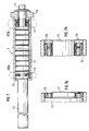
- Fig. 1 shows the rear end of the gun barrel 1 of an otherwise not shown artillery gun, on which the bottom piece 2 is arranged.
- a projectile rifle is arranged with a base frame 3 on which a guide track 5 is fastened, on which a carriage 4 is guided in a direction parallel to the barrel core axis R via slide guides 5.1.
- the carriage 4 is coupled via a connecting element 9 to a piston-cylinder drive 6, by means of which it can be accelerated in the direction of arrow B.
- a shock absorber 7 is arranged, which will be explained in more detail below and which has a stop 7.3 on its piston rod 7.2 which is led out of the slide to the front.
- the projectile 8 to be attached lies on the guide rails 4.3 arranged in the longitudinal direction in the carriage 4.
- the carriage 4 with the projectile 8 is shown in the starting position before the acceleration process begins.
- the end position of the slide is indicated in dashed lines by the end position of the piston rod 6.3 of the piston-cylinder drive 6 and the end position of the stop 7.3 of the shock absorber 7.
- stop 7.3 is located directly at the rear end of the gun barrel 1.
- the shock absorber 7 is arranged on the longitudinal center plane M of the carriage 4 and its central axis m runs through the center of mass of the slide 4 in a manner not particularly marked.
- a shell-like engagement element 4.1 which, as can be seen from FIGS. 5 and 6, is designed asymmetrically to the longitudinal center plane of the slide, since the projectile 8 is inserted from one side.
- the upper edge of the rear wall 4.2 of the engagement element 4.1 runs in such a way that the engagement point lies above the central axis A of the projectile 8 lying on the guide rails 4.3.
- the shock absorber 7 shows the structure of the shock absorber 7 in more detail.
- the shock absorber 7 has a cylinder 7.1, in which a piston 7.4 is guided, which carries a piston rod 7.2, at the outer end of which, not shown in FIG. 7, the stop 7.3 is arranged.
- the piston rod 7.2 is firmly connected to the piston 7.4 and the guide rod 7.7 and is guided in a holder 7.6 when the piston returns via the guide rod 7.7.
- a friction spring 7.5 is arranged in the space between the guide rod 7.7 and the inner wall of the cylinder 7.1. Friction springs of this type are generally known and their structure can be seen in FIGS. 7a and 7b, which represent an area at the two spring ends.
- the friction spring 7.5 is made up of a number of closed outer and inner rings, the outer rings on their inside and the inner rings on their outside having conical surfaces on which the outer and inner rings touch. If the spring pillar formed from the outer and inner rings is loaded in the direction of the spring axis, the conical surfaces slide into one another and cause the outer rings stretch and the inner rings decrease in diameter. Since outer inner rings are made of spring steel, an elastic compression occurs with correspondingly high forces, the special characteristic of this spring being the strong friction damping due to the friction between the outer and inner rings. In this way, about 2/3 of the energy introduced is converted into thermal energy by friction.
- a shock absorber constructed in this way is particularly advantageous for the projectile attachment described, because in this way the greater part, that is to say about 2/3, of the kinetic energy present in the braking position of the slide 4 is converted by friction, while the remainder is used for the return of the slide 4 is available in the starting position.
- a shock absorber that converts the entire kinetic energy of the slide when braking and to return the slide to the starting position with the aid of the drive system.
- the piston-cylinder drive 6 of the carriage 4 can in principle be driven hydraulically or pneumatically.
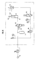
- a pneumatic drive with a control system as shown in FIG. 8 is particularly advantageous.
- the working connection 6.1 of the piston-cylinder drive 6 can be connected via an electromagnetically actuated control valve 10 on the one hand to an outlet and on the other hand to a compressed air reservoir 11.
- the compressed air reservoir 11 is connected to a compressed air source 14 in the usual way.
- the return connection 6.2 of the piston-cylinder drive 6 is via a quick exhaust valve til 12 on the one hand to an outlet and on the other hand via a second electromagnetically controllable control valve 13 with the interposition of a pressure limiter on the one hand to the compressed air reservoir 11 and on the other hand to an outlet.
- the control valve 10 is designed as a quick-opening valve, which is characterized by a very short switching time.
Landscapes
- Engineering & Computer Science (AREA)
- General Engineering & Computer Science (AREA)
- Actuator (AREA)
- Braking Arrangements (AREA)
- Preparation Of Clay, And Manufacture Of Mixtures Containing Clay Or Cement (AREA)
- Aiming, Guidance, Guns With A Light Source, Armor, Camouflage, And Targets (AREA)
- Orthopedics, Nursing, And Contraception (AREA)
- Acyclic And Carbocyclic Compounds In Medicinal Compositions (AREA)
- Pharmaceuticals Containing Other Organic And Inorganic Compounds (AREA)
Abstract
Description
Die Erfindung betrifft einen Geschoßansetzer für Artillerie mit den Merkmalen au dem Oberbegriff des Patentanspruchs 1.The invention relates to a projectile rifle for artillery with the features in the preamble of
Zum Beladen von Artilleriegeschützen ist es erforderlich, die 50 kg oder schwereren Artilleriegranaten mit einer Geschwindigkeit von mindestens 1,5 m/sec. soweit in das Rohr des Geschützes hineinzutreiben, daß der Weichmetall-Führungsring des Geschosses sich in den konischen Teil des Ladungsraumes einpreßt. Die Einpressung muß dabei so stark sein, daß das Geschoss auch bei höchster Erhöhung des Geschützrohres nicht mehr aufgrund seines Eigengewichtes herausfällt und gleichzeitig eine Abdichtung des Ladungsraumes nach vorne erfolgt.To load artillery guns, it is necessary to load the 50 kg or heavier artillery grenades at a speed of at least 1.5 m / sec. to drive into the barrel of the gun so far that the soft metal guide ring of the projectile is pressed into the conical part of the cargo space. The press-in must be so strong that the projectile no longer falls out due to its own weight, even when the gun barrel is very high, and at the same time the cargo space is sealed to the front.
Da ein manuelles Ansetzen des Geschosses durch die Besatzung zeitaufwendig ist und mit einer erheblichen physischen Belastung der Besatzungsmitglieder verbunden ist, wurden Geschoßansetzer verschiedener Bauart entwickelt, die das manuelle Ansetzen des Geschosses erübrigen sollen.Since manual insertion of the projectile by the crew is time-consuming and is associated with a considerable physical strain on the crew members, projectors of various types have been developed which are intended to dispense with the manual application of the projectile.
Eine besondere Bedeutung besitzen sogenannte Freiflugansetzer, denen das Prinzip zugrunde liegt, einer außerhalb des Geschützes befindlichen Granate eine so große Beschleunigung zu verleihen, daß nach Verlassen des Beschleunigungssystems die Granate aufgrund des aus der Beschleunigung in ihr vorhandenen Momentes sich im freien Flug weiterbewegt und der Ansetzvorgang auf diese Weise realisiert wird. Ein derartiger Freiflugansetzer ist beispielsweise in DE-OS 36 07 006 beschrieben.So-called free-flight attachments, which are based on the principle of giving a grenade outside the cannon such a great acceleration that after leaving the Acceleration system the grenade continues to move in free flight due to the existing moment from the acceleration and the attachment process is realized in this way. Such a free flight attachment is described for example in DE-OS 36 07 006.
Es sind weiterhin Freiflugansetzer mit den Merkmalen aus dem Oberbegriff des Patentanspruchs 1 bekannt, bei denen das auf dem Schlitten gelagerte Geschoß einschließlich Schlitten beschleunigt wird und beim Erreichen der erforderlichen Ansetzgeschwindigkeit der Schlitten abgebremst wird.Das Geschoß fliegt dann durch das Bodenstück und den Ladungsraum der Waffe und wird in den Zügen des Rohres angesetzt. Der Antrieb des Schlittens erfolgt durch einen pneumatisch oder hydraulisch betriebenen Kolben-Zylinderantrieb.There are also free-flight attachments with the features from the preamble of
Ein bei derartigen Freiflugansetzern auftretendes Problem besteht darin, daß einerseits zur Erzielung einer möglichst hohen Ansetzgeschwindigkeit eine große Beschleunigung des Systems Schlitten-Geschoß notwendig ist und andererseits die Richtung, in der das Geschoß sich bei der Abbremsung vom Schlitten löst, mit hoher Genauigkeit fluchtend zur Rohrseelenachse der Waffe liegen muß, damit beim Durchfliegen des Bodenstückes und des Ladungsraums der Waffe keine Berührung zwischen dem Geschoß und den Innenwänden der Waffe stattfindet, die zu Beschädigungen am Geschoß oder an der Waffe führen können. Da der hier zur Verfügung stehende Spielraum im allgemeinen nur wenige Millimeter beträgt, muß dafür gesorgt werden, daß beim Abbremsen des Schlittens keine Störkräfte auftreten, welche zu Momenten an der Ansetzerkonstruktion führen und zur Folge haben, daß die Abflugrichtung des Geschosses von der Richtung der Rohrseelenachse abweicht.A problem that occurs with such free-flight launchers is that, on the one hand, a high acceleration of the sled-projectile system is necessary to achieve the highest possible attachment speed, and on the other hand, the direction in which the projectile detaches from the sled during braking is aligned with the tube core axis with high accuracy the weapon must lie so that there is no contact between the projectile and the inside walls of the weapon when flying through the base piece and the cargo space of the weapon, which can lead to damage to the projectile or to the weapon. Since the scope available here is generally only a few millimeters, care must be taken to ensure that when the slide is braked there are no disruptive forces which lead to moments on the piecing construction and have the consequence that the direction of departure of the projectile is from the direction of the tube core axis deviates.
Der Erfindung liegt die Aufgabe zugrunde, einen Geschoßansetzer mit den Merkmalen aus dem Oberbegriff des Patentanspruchs 1 so auszubilden, daß auch bei hoher Beschleunigung beim Abbremsvorgang keine Störkräfte auftreten, die das Geschoß beim Ansetzvorgang negativ beeinflussen könnten.The invention has for its object to provide a projectile rifle with the features from the preamble of
Die Lösung dieser Aufgabe erfolgt erfindungsgemäß mit den Merkmalen aus dem kennzeichnenden Teil des Patentanspruchs 1. Vorteilhafte Weiterbildungen des erfindungsgemäßen Geschoßansetzers sind in den Unteransprüchen beschrieben.This object is achieved according to the invention with the features from the characterizing part of
Wie weiter unten anhand eines Ausführungsbeispiels noch genauer erläutert, besteht der Grundgedanke der Erfindung darin, den Schlitten dadurch abzubremsen, daß er unter Zwischenschaltung eines Stoßdämpfers direkt auf das hintere Ende des Geschützrohres aufläuft. Dies hat infolge der sehr großen Masse des Geschützrohres die Folge, daß keine Abkippbewegung des Schlittens beim Abbremsvorgang auftritt, wie dies der Fall ist, wenn das Abbremsen beispielsweise durch Anschläge am Grundgestell der Führungsbahn des Schlittens oder durch Anschläge in der Antriebsvorrichtung erfolgt. Der zwischengeschaltete Stoßdämpfer ist auf der Längsmittelebene des Schlittens angeordnet und läuft vorzugsweise mindestens angenähert durch den Massenschwerpunkt des Schlittens, wodurch weiterhin sichergestellt wird, daß keine störenden Momente beim Abbremsvorgang auftreten. Es hat sich weiterhin als besonders vorteilhaft erwiesen, wenn der Schlitten in Längsrichtung verlaufende Führungsschienen für das Geschoß aufweist und das am hinteren Ende des Schlittens angeordnete Angriffselement am Geschoß oberhalb der Mittelachse des Geschosses angreift. Hierdurch wird verhindert, daß das Geschoß bei der Ablösung vom Schlitten eine Bewegung ausführt, bei der es sich mit der Spitze nach oben aufrichtet. Es wird vielmehr in der Beschleunigungsphase eine absolut stabile Lage auch bei unterschiedlichen Geschossen erreicht.As explained in more detail below with the aid of an exemplary embodiment, the basic idea of the invention is to brake the carriage by running directly onto the rear end of the gun barrel with the interposition of a shock absorber. This has the consequence of the very large mass of the gun barrel that no tilting movement of the carriage occurs during the braking process, as is the case when braking is carried out, for example, by stops on the base frame of the guideway of the carriage or by stops in the drive device. The intermediate shock absorber is arranged on the longitudinal center plane of the slide and preferably runs at least approximately through the center of gravity of the slide, which further ensures that no disturbing moments occur during the braking process. It has also proven to be particularly advantageous if the carriage has longitudinal guide rails for the projectile and the engagement element arranged at the rear end of the carriage engages the projectile above the central axis of the projectile. This prevents the projectile from performing a movement when it detaches from the slide, with the tip rising upwards. It is rather in reached an absolutely stable position during the acceleration phase even on different storeys.
Wenn der Stoßdämpfer nur einen gewissen Anteil der kinetischen Energie des Schlittens beim Abbremsen aufnimmt, kann die restliche Energie zur Rückführung des Schlittens in die Ausgangslage ausgenutzt werden, wobei der bei Erreichen der Ausgangslage noch vorhandene Energieüberschuß durch einen weiteren Stoßdämpfer aufgenommen wird, der in das Antriebssystem integriert sein kann.If the shock absorber only absorbs a certain proportion of the kinetic energy of the sled when braking, the remaining energy can be used to return the sled to the starting position, the excess energy still present when the starting position is reached being absorbed by another shock absorber which is incorporated into the drive system can be integrated.
Zum Antrieb des Schlittens dient vorzugsweise ein pneumatisches System, bei dem die zum Betreiben des Kolben-Zylinderantriebs erforderliche Druckluft in einem Druckluftspeicher gespeichert ist und mittels eines schnellöffnenden Steuerventils schlagartig dem Kolben-Zylinderantrieb zugeführt wird.A pneumatic system is preferably used to drive the slide, in which the compressed air required to operate the piston-cylinder drive is stored in a compressed air reservoir and is suddenly supplied to the piston-cylinder drive by means of a quick-opening control valve.
Im folgenden wird anhand der beigefügten Zeichnungen ein Ausführungsbeispiel für einen Geschoßansetzer nach der Erfindung näher erläutert.In the following an embodiment of a projectile according to the invention will be explained in more detail with reference to the accompanying drawings.
In den Zeichnungen zeigen:
- Fig. 1 in einer stark schematisierten Darstellung im Längsschnitt das hintere Ende eines Geschützrohres mit einem daran angeordneten Geschoßansetzer;
- Fig. 2 eine Seitenansicht des Schlittens bei einem Geschoßansetzer nach Fig. 1 ;
- Fig. 3 eine Aufsicht auf den Schlitten nach Fig. 1;
- Fig. 4 einen Schnitt nach der Linie IV-IV in Fig. 3;
- Fig. 5 eine Ansicht des Schlittens nach Fig. 2 bis 4 von vorne;
- Fig. 6 in leicht vergrößerter Darstellung einen Schnitt nach der Linie VI-VI in Fig. 4;
- Fig. 7 einen Schnitt durch den Stoßdämpfer für den Schlitten nach Fig. 2 bis 6;
- Fig. 7a und 7b Einzelheiten des Stoßdämpfers nach Fig. 7 in den Bereichen VIIa und VIIb;
- Fig. 8 in einem Schaltbild das pneumatische Steuersystem für den Geschoßansetzer nach Fig. 1 bis 7.
- Figure 1 is a highly schematic representation in longitudinal section of the rear end of a gun barrel with a projectile attached to it.
- FIG. 2 shows a side view of the slide in a projectile rammer according to FIG. 1;
- Fig. 3 is a plan view of the carriage of Fig. 1;
- Fig. 4 is a section along the line IV-IV in Fig. 3;
- 5 shows a view of the carriage according to FIGS. 2 to 4 from the front;
- Figure 6 is a slightly enlarged view of a section along the line VI-VI in Fig. 4.
- 7 shows a section through the shock absorber for the carriage according to FIGS. 2 to 6;
- 7a and 7b details of the shock absorber according to FIG. 7 in the areas VIIa and VIIb;
- 8 is a circuit diagram of the pneumatic control system for the projectile rifle according to FIGS. 1 to 7.
Fig. 1 zeigt das hintere Ende des Geschützrohres 1 eines im übrigen nicht dargestellten Artilleriegeschützes, an dem das Bodenstück 2 angeordnet ist. Hinter dem Geschützrohr 1 ist ein Geschoßansetzer angeordnet mit einem Grundgestell 3, auf dem eine Führungsbahn 5 befestigt ist, auf der ein Schlitten 4 über Gleitführungen 5.1 in einer Richtung parallel zur Rohrseelenachse R geführt ist. Der Schlitten 4 ist über ein Verbindungselement 9 mit einem Kolben-Zylinderantrieb 6 gekoppelt, durch den er in Pfeilrichtung B beschleunigt werden kann. In Längsrichtung des Schlittens 4 ist ein Stoßdämpfer 7 angeordnet, der weiter unten näher erläutert wird und der an seiner aus dem Schlitten nach vorne herausgeführten Kolbenstange 7.2 einen Anschlag 7.3 aufweist. Auf den im Schlitten 4 in Längsrichtung angeordneten Führungsschienen 4.3 liegt das anzusetzende Geschoß 8. In Fig. 1 ist der Schlitten 4 mit dem Geschoß 8 in der Ausgangsposition vor Beginn des Beschleunigungsvorganges dargestellt. Die Endposition des Schlittens ist in gestrichelten Linien durch die Endlage der Kolbenstange 6.3 des Kolben-Zylinderantriebs 6 und die Endlage des Anschlags 7.3 des Stoßdämpfers 7 angedeutet. Wie Fig. 1 zu entnehmen, liegt in der Endlage des Schlittens 4 Anschlag 7.3 unmittelbar am hinteren Ende des Geschützrohres 1 an.Fig. 1 shows the rear end of the
In den Fig. 2 bis 6 ist die Konstruktion des Schlittens etwas detaillierter dargestellt. Der Stoßdämpfer 7 ist auf der Längsmittelebene M des Schlittens 4 angeordnet une seine Mittelachse m läuft in nicht besonders gekennzeichneter Weise durch den Massenschwerpunkt des Schlittens 4.2 to 6, the construction of the carriage is shown in somewhat more detail. The shock absorber 7 is arranged on the longitudinal center plane M of the
Am hinteren Ende des Schlittens 4 ist ein schalenartiges Angriffselement 4.1 angeordnet, das, wie aus den Fig. 5 und 6 zu entnehmen, asymmetrisch zur Längsmittelebene des Schlittens ausgebildet ist, da das Einlegen des Geschosses 8 von einer Seite her erfolgt. Die Oberkante der Rückwand 4.2 des Angriffselementes 4.1 verläuft so, daß der Angriffspunkt oberhalb der Mittelachse A des auf den Führungsschienen 4.3 liegenden Geschosses 8 liegt.At the rear end of the
In Fig. 7 ist der Aufbau des Stoßdämpfers 7 genauer dargestellt. Der Stoßdämpfer 7 besitzt einen Zylinder 7.1, in dem ein Kolben 7.4 geführt ist, der eine Kolbenstange 7.2 trägt, an deren äußerem Ende, in Fig. 7 nicht dargestellt, der Anschlag 7.3 angeordnet ist. Die Kolbenstange 7.2 ist mit dem Kolben 7.4 und der Führungsstange 7.7 fest verbunden und wird beim Rücklauf des Kolbens über die Führungsstange 7.7 in einer Halterung 7.6 geführt. Im Raum zwischen der Führungsstange 7.7 und der Innenwand des Zylinders 7.1 ist eine Reibungsfeder 7.5 angeordnet. Derartige Reibungsfedern sind allgemein bekannt und ihr Aufbau ist den Fig. 7a und 7b, die einen Bereich an den beiden Federenden darstellen, zu entnehmen. Die Reibungsfeder 7.5 ist aus einer Anzahl von geschlossenen Außen- und Innenringen aufgebaut, wobei die Außenringe an ihrer Innenseite und die Innenringe an ihrer Außenseite Kegelflächen aufweisen, an denen sich die Außen-und Innenringe berühren. Wird die aus den Außen- und Innenringen gebildete Federsäule in Richtung der Federachse belastet, so schieben sich die Kegelflächen ineinander und bewirken, daß sich die Außenringe dehnen und sich die Innenringe im Durchmesser verkleinern. Da Außen- Innenringe aus Federstahl bestehen, tritt bei entsprechend hohen Kräften eine elastische Stauchung auf, wobei das besondere Kennzeichen dieser Feder in der starken Reibungsdämpfung aufgrund der Reibung zwischen den Außen- und Innenringen ist. Auf diese Weise werden etwa 2/3 der eingeleiteten Energie durch Reibung in Wärmeenergie umgesetzt.7 shows the structure of the shock absorber 7 in more detail. The shock absorber 7 has a cylinder 7.1, in which a piston 7.4 is guided, which carries a piston rod 7.2, at the outer end of which, not shown in FIG. 7, the stop 7.3 is arranged. The piston rod 7.2 is firmly connected to the piston 7.4 and the guide rod 7.7 and is guided in a holder 7.6 when the piston returns via the guide rod 7.7. A friction spring 7.5 is arranged in the space between the guide rod 7.7 and the inner wall of the cylinder 7.1. Friction springs of this type are generally known and their structure can be seen in FIGS. 7a and 7b, which represent an area at the two spring ends. The friction spring 7.5 is made up of a number of closed outer and inner rings, the outer rings on their inside and the inner rings on their outside having conical surfaces on which the outer and inner rings touch. If the spring pillar formed from the outer and inner rings is loaded in the direction of the spring axis, the conical surfaces slide into one another and cause the outer rings stretch and the inner rings decrease in diameter. Since outer inner rings are made of spring steel, an elastic compression occurs with correspondingly high forces, the special characteristic of this spring being the strong friction damping due to the friction between the outer and inner rings. In this way, about 2/3 of the energy introduced is converted into thermal energy by friction.
Für den beschriebenen Geschoßansetzer ist ein derartig aufgebauter Stoßdämpfer besonders vorteilhaft, weil auf diese Weise der größere Teil, also etwa 2/3, der in Abbremsposition des Schlittens 4 vorhandenen kinetischen Energie durch Reibung umgesetzt werden, während der verbleibende Rest für den Rücklauf des Schlittens 4 in die Ausgangsposition zur Verfügung steht. Selbstverständlich ist es auch möglich, einen Stoßdämpfer einzusetzen, der die gesamte kinetische Energie des Schlittens beim Abbremsen umsetzt und den Schlitten mit Hilfe des Antriebssystems wieder in die Ausgangslage zurückzuführen. Der Kolben-Zylinderantrieb 6 des Schlittens 4 kann im Prinzip hydraulisch oder pneumatisch angetrieben sein.A shock absorber constructed in this way is particularly advantageous for the projectile attachment described, because in this way the greater part, that is to say about 2/3, of the kinetic energy present in the braking position of the
Besonders vorteilhaft ist ein pneumatischer Antrieb mit einem Steuersystem wie es in Fig. 8 dargestellt ist.A pneumatic drive with a control system as shown in FIG. 8 is particularly advantageous.
Bei dem pneumatischen Steuersystem nach Fig. 8 ist der Arbeitsanschluß 6.1 des Kolben-Zylinderantriebs 6 über ein elektromagnetisch betätigbares Steuerventil 10 einerseits mit einem Auslaß und andererseits mit einem Druckluftspeicher 11 verbindbar. Der Druckluftspeicher 11 ist in der üblichen Weise an eine Druckluftquelle 14 angeschlossen. Der Rücklaufanschluß 6.2 des Kolben-Zylinderantriebs 6 ist über ein Schnellentlüftungsven til 12 einerseits an einen Auslaß und andererseits über ein zweites elektromagnetisch ansteuerbares Steuerventil 13 unter Zwischenschaltung eines Druckbegrenzers einerseits an den Druckluftspeicher 11 und andererseits an einen Auslaß anschließbar. Das Steuerventil 10 ist als schnellöffendes Ventil ausgebildet, das sich durch eine sehr kurze Schaltzeit auszeichnet. Dadurch wird erreicht, daß der benötigte Volumenstrom schnell am Kolben-Zylinderantrieb 6 zur Verfügung steht. Bei Einleitung der Beschleunigung steht so schlagartig ein Druck von beispielsweise 30 bar zur Verfügung, durch den der Kolben nach vorne geführt wird und den Schlitten beschleunigt. Dabei wird die auf der anderen Seite des Kolbens befindliche Luftsäule beim Beschleunigungshub über das Schnellentlüftungsventil 12 ausgestoßen. Am Ende des Beschleunigungshubes wird der Schlitten 4 abgebremst, wobei, wie erwähnt, etwa 2/3 der kinetischen Energie umgesetzt werden und die Restenergie für eine Rückstellkraft zur Verfügung steht, durch die der Schlitten 4 in die Ausgangslage zurückgeführt wird. Bei der entsprechenden Kolbenbewegung im Kolben-Zylinderantrieb 6 wird die Luft durch den Arbeitsanschluß 6.1 und das entsprechend umgesteuerte Steuerventil 10 über eine Drossel 15 geführt, so daß bei dieser Bewegung der Kolben-Zylinderantrieb 6 als Stoßdämpfer wirkt, durch den die Restenergie umgesetzt wird. Es ist aber auch möglich, den Schlitten 4 zurückzuführen, indem der Rücklaufanschluß 6.2 über das zweite Steuerventil 13 und einen Druckbegrenzer 16 mit dem Druckluftspeicher 11 verbunden wird, wobei nunmehr dem Kolben-Zylinderantrieb 6 ein reduzierter Druck von beispielsweise 7 bar zugeführt wird, durch den der Schlitten 4 in die Ausgangsposition zurückgeführt wird. Durch diese Ansteuerung wird erreicht, daß der Schlitten 4 wieder in eine definierte Endlage zurückgestellt wird.In the pneumatic control system according to FIG. 8, the working connection 6.1 of the piston-
Claims (8)
Priority Applications (1)
| Application Number | Priority Date | Filing Date | Title |
|---|---|---|---|
| AT89113036T ATE87732T1 (en) | 1988-07-28 | 1989-07-15 | ARTILLERY MISSILE. |
Applications Claiming Priority (2)
| Application Number | Priority Date | Filing Date | Title |
|---|---|---|---|
| DE3825662 | 1988-07-28 | ||
| DE3825662A DE3825662A1 (en) | 1988-07-28 | 1988-07-28 | BULLET RING FOR ARTILLERY |
Publications (3)
| Publication Number | Publication Date |
|---|---|
| EP0352584A2 true EP0352584A2 (en) | 1990-01-31 |
| EP0352584A3 EP0352584A3 (en) | 1990-08-16 |
| EP0352584B1 EP0352584B1 (en) | 1993-03-31 |
Family
ID=6359765
Family Applications (1)
| Application Number | Title | Priority Date | Filing Date |
|---|---|---|---|
| EP89113036A Expired - Lifetime EP0352584B1 (en) | 1988-07-28 | 1989-07-15 | Projectile rammer for the ordnance |
Country Status (4)
| Country | Link |
|---|---|
| US (1) | US4957028A (en) |
| EP (1) | EP0352584B1 (en) |
| AT (1) | ATE87732T1 (en) |
| DE (2) | DE3825662A1 (en) |
Cited By (6)
| Publication number | Priority date | Publication date | Assignee | Title |
|---|---|---|---|---|
| WO2000043723A1 (en) * | 1999-01-20 | 2000-07-27 | Bofors Weapon Systems Ab | Loading system |
| DE19914663A1 (en) * | 1999-03-31 | 2000-10-05 | Krauss Maffei Wegmann Gmbh & C | Missile launchers for an artillery piece |
| DE19955234A1 (en) * | 1999-11-17 | 2001-05-23 | Krauss Maffei Wegmann Gmbh & C | Missile launchers for artillery |
| US6457397B1 (en) * | 1999-07-22 | 2002-10-01 | Giat Industries | Loading device for a shell in the cannon chamber of a weapon fitted with a screw breech |
| FR2824131A1 (en) | 2001-04-30 | 2002-10-31 | Giat Ind Sa | Artillery projectile loading system has cradle to support projectile as it is delivered by trolley |
| CN105571385A (en) * | 2015-12-15 | 2016-05-11 | 湖北江华机械有限公司 | Grenade launcher with sensitive grenade feeding device |
Families Citing this family (9)
| Publication number | Priority date | Publication date | Assignee | Title |
|---|---|---|---|---|
| SE9201434L (en) * | 1992-05-06 | 1993-11-07 | Bofors Ab | rammer |
| RU2148230C1 (en) * | 1999-06-23 | 2000-04-27 | Государственное унитарное предприятие "Конструкторское бюро приборостроения" | Artillery shot feeding mechanism |
| RU2163334C1 (en) * | 1999-06-25 | 2001-02-20 | Государственное унитарное предприятие Конструкторское бюро приборостроения | Artillery mount ramming mechanism |
| SE9903440L (en) | 1999-09-23 | 2001-02-26 | Bofors Weapon Sys Ab | Method and apparatus for loading artillery pieces by casting |
| RU2191336C2 (en) * | 2000-04-07 | 2002-10-20 | Федеральное государственное унитарное предприятие "Уральское конструкторское бюро транспортного машиностроения" | Method for control of the rate of feed of guided missile by automatic loading unit of tank gun |
| US20080216640A1 (en) * | 2005-01-27 | 2008-09-11 | John Brand | Lightweight rammer |
| ITMI20070106A1 (en) * | 2007-01-24 | 2008-07-25 | Beretta Armi Spa | SEMI-AUTOMATIC RIFULOUS RIFLE |
| FR2945616B1 (en) * | 2009-05-13 | 2011-07-29 | Nexter Systems | DEVICE FOR LOADING A MUNITION |
| DE102017107442B4 (en) * | 2017-04-06 | 2021-03-18 | Krauss-Maffei Wegmann Gmbh & Co. Kg | Device for loading a barrel weapon with ammunition bodies |
Family Cites Families (12)
| Publication number | Priority date | Publication date | Assignee | Title |
|---|---|---|---|---|
| DE151461C (en) * | ||||
| US789885A (en) * | 1903-03-24 | 1905-05-16 | Charles Prosper Eugene Schneider | Apparatus for the rapid charging of guns. |
| GB335895A (en) * | 1929-06-01 | 1930-10-01 | Bofors Ab | Automatic loading device for barrel recoil guns |
| US2593412A (en) * | 1943-11-13 | 1952-04-22 | George A Chadwick | Gun rammer |
| GB784739A (en) * | 1950-04-11 | 1957-10-16 | Westinghouse Electric Int Co | Improvements in or relating to automatic rammer mechanisms for guns |
| US3584532A (en) * | 1969-09-16 | 1971-06-15 | Oberlikon Buehrle Holding Ag Z | Automatic gun with ejection actuated rammer |
| SE413342B (en) * | 1976-03-31 | 1980-05-19 | Bofors Ab | ANSETTARANORDNING |
| US4291611A (en) * | 1979-10-18 | 1981-09-29 | The United States Of America As Represented By The Secretary Of The Army | Automatic loading device |
| SE431794B (en) * | 1979-12-18 | 1984-02-27 | Bofors Ab | DEVICE FOR CONTROL OF A EMPLOYEE HEAD IN ITS DIRECTION |
| CH662175A5 (en) * | 1984-11-15 | 1987-09-15 | Sig Schweiz Industrieges | Acceleration device for a loading device of a gun |
| DE3607006A1 (en) * | 1986-03-04 | 1987-09-10 | Wegmann & Co | FREE FLIGHTER FOR ARTILLERY BULLETS |
| CH664627A5 (en) * | 1986-11-20 | 1988-03-15 | Sig Schweiz Industrieges | ACCELERATION DEVICE FOR A LOADING DEVICE OF A BULLET. |
-
1988
- 1988-07-28 DE DE3825662A patent/DE3825662A1/en not_active Withdrawn
-
1989
- 1989-07-14 US US07/380,928 patent/US4957028A/en not_active Expired - Lifetime
- 1989-07-15 DE DE8989113036T patent/DE58903931D1/en not_active Expired - Fee Related
- 1989-07-15 AT AT89113036T patent/ATE87732T1/en not_active IP Right Cessation
- 1989-07-15 EP EP89113036A patent/EP0352584B1/en not_active Expired - Lifetime
Cited By (9)
| Publication number | Priority date | Publication date | Assignee | Title |
|---|---|---|---|---|
| WO2000043723A1 (en) * | 1999-01-20 | 2000-07-27 | Bofors Weapon Systems Ab | Loading system |
| DE19914663A1 (en) * | 1999-03-31 | 2000-10-05 | Krauss Maffei Wegmann Gmbh & C | Missile launchers for an artillery piece |
| EP1041355A3 (en) * | 1999-03-31 | 2002-01-16 | Krauss-Maffei Wegmann GmbH & Co. KG | Ramming device for artillery gun |
| US6457397B1 (en) * | 1999-07-22 | 2002-10-01 | Giat Industries | Loading device for a shell in the cannon chamber of a weapon fitted with a screw breech |
| DE19955234A1 (en) * | 1999-11-17 | 2001-05-23 | Krauss Maffei Wegmann Gmbh & C | Missile launchers for artillery |
| EP1102023A2 (en) | 1999-11-17 | 2001-05-23 | Krauss-Maffei Wegmann GmbH & Co. KG | Rammer for an artillery gun |
| EP1102023A3 (en) * | 1999-11-17 | 2002-02-06 | Krauss-Maffei Wegmann GmbH & Co. KG | Rammer for an artillery gun |
| FR2824131A1 (en) | 2001-04-30 | 2002-10-31 | Giat Ind Sa | Artillery projectile loading system has cradle to support projectile as it is delivered by trolley |
| CN105571385A (en) * | 2015-12-15 | 2016-05-11 | 湖北江华机械有限公司 | Grenade launcher with sensitive grenade feeding device |
Also Published As
| Publication number | Publication date |
|---|---|
| EP0352584A3 (en) | 1990-08-16 |
| ATE87732T1 (en) | 1993-04-15 |
| DE3825662A1 (en) | 1990-02-08 |
| DE58903931D1 (en) | 1993-05-06 |
| EP0352584B1 (en) | 1993-03-31 |
| US4957028A (en) | 1990-09-18 |
Similar Documents
| Publication | Publication Date | Title |
|---|---|---|
| EP0352584B1 (en) | Projectile rammer for the ordnance | |
| DE3505443C2 (en) | ||
| DE2951904A1 (en) | LOCKING DEVICE FOR A SUB-CALIBAR FLOOR | |
| DE1578402A1 (en) | Self-acting firearm with a bolt housing that can be reversed on a carrier | |
| AT507982B1 (en) | GAS-PRESSED FIREARMS DEVICE | |
| EP0163626B1 (en) | Cannon | |
| CH668635A5 (en) | BRAKE SLEEVE AND COUNTERMEASURE FOR A DEVICE FOR SHOCK-FREE SHOOTING. | |
| DE661306C (en) | Firearm without firing pin and cartridge for firing from the same | |
| DE2300909B2 (en) | MULTI-STAGE MECHANICAL-HYDRAULIC DAMPING DEVICE FOR THE FORWARD MOVEMENT OF THE SLIDING TUBE OF AN INDEPENDENT FIRE ARM | |
| DE3015102C2 (en) | Weapon advance damper for a machine gun with a wedge lock | |
| DE19524418A1 (en) | Revolver recoil retardation by counter-mass - uses charge to drive counter-masses, which may form part of self loading or rapid fire system, in opposite ways giving mass compensating action to absorb reaction without loss of aim | |
| DE102021206949B3 (en) | Low-noise weapon balancing device in a submarine and method of operation | |
| DE1578029B1 (en) | Tubular launcher for projectiles, especially for guided projectiles | |
| DE69303113T2 (en) | Gun attachment | |
| DE4009050C2 (en) | ||
| DE506252C (en) | Gas pressure charger | |
| DE2949218C2 (en) | Ammunition ignition device on a barrel weapon | |
| EP4014003B1 (en) | Recoil brake and barreled firearm | |
| DE10139868A1 (en) | Gas-propelled fire arm has cylindrical lock containing damping piston, one end of which fits against pressure chamber while opposite end is mounted on spring, mass of piston being several times that of lock | |
| DE3206642A1 (en) | Muzzle attachment for high-powered barrel weapons | |
| EP0114204A2 (en) | Gas-operated automatic fire-arm | |
| EP0239755B1 (en) | Rammer for ordnance | |
| EP1041355B1 (en) | Ramming device for artillery gun | |
| EP0145696B1 (en) | Projectile weapon, particularly an armour piercing weapon | |
| DE2313984C2 (en) | Guide ring for self-propelled bullets |
Legal Events
| Date | Code | Title | Description |
|---|---|---|---|
| PUAI | Public reference made under article 153(3) epc to a published international application that has entered the european phase |
Free format text: ORIGINAL CODE: 0009012 |
|
| AK | Designated contracting states |
Kind code of ref document: A2 Designated state(s): AT BE CH DE FR GB IT LI NL SE |
|
| PUAL | Search report despatched |
Free format text: ORIGINAL CODE: 0009013 |
|
| AK | Designated contracting states |
Kind code of ref document: A3 Designated state(s): AT BE CH DE FR GB IT LI NL SE |
|
| 17P | Request for examination filed |
Effective date: 19900914 |
|
| 17Q | First examination report despatched |
Effective date: 19911121 |
|
| GRAA | (expected) grant |
Free format text: ORIGINAL CODE: 0009210 |
|
| ITF | It: translation for a ep patent filed | ||
| AK | Designated contracting states |
Kind code of ref document: B1 Designated state(s): AT BE CH DE FR GB IT LI NL SE |
|
| PG25 | Lapsed in a contracting state [announced via postgrant information from national office to epo] |
Ref country code: BE Effective date: 19930331 Ref country code: SE Effective date: 19930331 |
|
| REF | Corresponds to: |
Ref document number: 87732 Country of ref document: AT Date of ref document: 19930415 Kind code of ref document: T |
|
| REF | Corresponds to: |
Ref document number: 58903931 Country of ref document: DE Date of ref document: 19930506 |
|
| GBT | Gb: translation of ep patent filed (gb section 77(6)(a)/1977) |
Effective date: 19930413 |
|
| ET | Fr: translation filed | ||
| PG25 | Lapsed in a contracting state [announced via postgrant information from national office to epo] |
Ref country code: AT Effective date: 19930715 |
|
| PLBE | No opposition filed within time limit |
Free format text: ORIGINAL CODE: 0009261 |
|
| STAA | Information on the status of an ep patent application or granted ep patent |
Free format text: STATUS: NO OPPOSITION FILED WITHIN TIME LIMIT |
|
| 26N | No opposition filed | ||
| REG | Reference to a national code |
Ref country code: GB Ref legal event code: IF02 |
|
| PGFP | Annual fee paid to national office [announced via postgrant information from national office to epo] |
Ref country code: DE Payment date: 20070810 Year of fee payment: 19 |
|
| PGFP | Annual fee paid to national office [announced via postgrant information from national office to epo] |
Ref country code: CH Payment date: 20070724 Year of fee payment: 19 |
|
| PGFP | Annual fee paid to national office [announced via postgrant information from national office to epo] |
Ref country code: GB Payment date: 20070730 Year of fee payment: 19 |
|
| PGFP | Annual fee paid to national office [announced via postgrant information from national office to epo] |
Ref country code: IT Payment date: 20070726 Year of fee payment: 19 Ref country code: NL Payment date: 20070717 Year of fee payment: 19 |
|
| PGFP | Annual fee paid to national office [announced via postgrant information from national office to epo] |
Ref country code: FR Payment date: 20070718 Year of fee payment: 19 |
|
| REG | Reference to a national code |
Ref country code: CH Ref legal event code: PFA Owner name: WEGMANN & CO. GMBH Free format text: WEGMANN & CO. GMBH#AUGUST-BODE-STRASSE 1#D-34127 KASSEL (DE) -TRANSFER TO- WEGMANN & CO. GMBH#AUGUST-BODE-STRASSE 1#D-34127 KASSEL (DE) |
|
| REG | Reference to a national code |
Ref country code: CH Ref legal event code: PL |
|
| GBPC | Gb: european patent ceased through non-payment of renewal fee |
Effective date: 20080715 |
|
| NLV4 | Nl: lapsed or anulled due to non-payment of the annual fee |
Effective date: 20090201 |
|
| PG25 | Lapsed in a contracting state [announced via postgrant information from national office to epo] |
Ref country code: DE Free format text: LAPSE BECAUSE OF NON-PAYMENT OF DUE FEES Effective date: 20090203 |
|
| REG | Reference to a national code |
Ref country code: FR Ref legal event code: ST Effective date: 20090331 |
|
| PG25 | Lapsed in a contracting state [announced via postgrant information from national office to epo] |
Ref country code: NL Free format text: LAPSE BECAUSE OF NON-PAYMENT OF DUE FEES Effective date: 20090201 |
|
| PG25 | Lapsed in a contracting state [announced via postgrant information from national office to epo] |
Ref country code: GB Free format text: LAPSE BECAUSE OF NON-PAYMENT OF DUE FEES Effective date: 20080715 Ref country code: LI Free format text: LAPSE BECAUSE OF NON-PAYMENT OF DUE FEES Effective date: 20080731 Ref country code: CH Free format text: LAPSE BECAUSE OF NON-PAYMENT OF DUE FEES Effective date: 20080731 |
|
| PG25 | Lapsed in a contracting state [announced via postgrant information from national office to epo] |
Ref country code: FR Free format text: LAPSE BECAUSE OF NON-PAYMENT OF DUE FEES Effective date: 20080731 Ref country code: IT Free format text: LAPSE BECAUSE OF NON-PAYMENT OF DUE FEES Effective date: 20080715 |