EP0354439B1 - Corrosion-resistant hinge for casements or the like - Google Patents
Corrosion-resistant hinge for casements or the like Download PDFInfo
- Publication number
- EP0354439B1 EP0354439B1 EP89114099A EP89114099A EP0354439B1 EP 0354439 B1 EP0354439 B1 EP 0354439B1 EP 89114099 A EP89114099 A EP 89114099A EP 89114099 A EP89114099 A EP 89114099A EP 0354439 B1 EP0354439 B1 EP 0354439B1
- Authority
- EP
- European Patent Office
- Prior art keywords
- hinge
- pin
- fork
- plastic material
- stem
- Prior art date
- Legal status (The legal status is an assumption and is not a legal conclusion. Google has not performed a legal analysis and makes no representation as to the accuracy of the status listed.)
- Expired - Lifetime
Links
Images
Classifications
-
- E—FIXED CONSTRUCTIONS
- E05—LOCKS; KEYS; WINDOW OR DOOR FITTINGS; SAFES
- E05D—HINGES OR SUSPENSION DEVICES FOR DOORS, WINDOWS OR WINGS
- E05D5/00—Construction of single parts, e.g. the parts for attachment
- E05D5/02—Parts for attachment, e.g. flaps
-
- E—FIXED CONSTRUCTIONS
- E05—LOCKS; KEYS; WINDOW OR DOOR FITTINGS; SAFES
- E05D—HINGES OR SUSPENSION DEVICES FOR DOORS, WINDOWS OR WINGS
- E05D11/00—Additional features or accessories of hinges
- E05D11/02—Lubricating arrangements
-
- E—FIXED CONSTRUCTIONS
- E05—LOCKS; KEYS; WINDOW OR DOOR FITTINGS; SAFES
- E05D—HINGES OR SUSPENSION DEVICES FOR DOORS, WINDOWS OR WINGS
- E05D5/00—Construction of single parts, e.g. the parts for attachment
- E05D5/10—Pins, sockets or sleeves; Removable pins
-
- E—FIXED CONSTRUCTIONS
- E05—LOCKS; KEYS; WINDOW OR DOOR FITTINGS; SAFES
- E05D—HINGES OR SUSPENSION DEVICES FOR DOORS, WINDOWS OR WINGS
- E05D9/00—Flaps or sleeves specially designed for making from particular material, e.g. hoop-iron, sheet metal, plastics
- E05D9/005—Flaps or sleeves specially designed for making from particular material, e.g. hoop-iron, sheet metal, plastics from plastics
-
- E—FIXED CONSTRUCTIONS
- E05—LOCKS; KEYS; WINDOW OR DOOR FITTINGS; SAFES
- E05Y—INDEXING SCHEME ASSOCIATED WITH SUBCLASSES E05D AND E05F, RELATING TO CONSTRUCTION ELEMENTS, ELECTRIC CONTROL, POWER SUPPLY, POWER SIGNAL OR TRANSMISSION, USER INTERFACES, MOUNTING OR COUPLING, DETAILS, ACCESSORIES, AUXILIARY OPERATIONS NOT OTHERWISE PROVIDED FOR, APPLICATION THEREOF
- E05Y2201/00—Constructional elements; Accessories therefor
- E05Y2201/20—Brakes; Disengaging means; Holders; Stops; Valves; Accessories therefor
- E05Y2201/218—Holders
- E05Y2201/22—Locks
-
- E—FIXED CONSTRUCTIONS
- E05—LOCKS; KEYS; WINDOW OR DOOR FITTINGS; SAFES
- E05Y—INDEXING SCHEME ASSOCIATED WITH SUBCLASSES E05D AND E05F, RELATING TO CONSTRUCTION ELEMENTS, ELECTRIC CONTROL, POWER SUPPLY, POWER SIGNAL OR TRANSMISSION, USER INTERFACES, MOUNTING OR COUPLING, DETAILS, ACCESSORIES, AUXILIARY OPERATIONS NOT OTHERWISE PROVIDED FOR, APPLICATION THEREOF
- E05Y2600/00—Mounting or coupling arrangements for elements provided for in this subclass
- E05Y2600/60—Mounting or coupling members; Accessories therefor
- E05Y2600/622—Dowels; Pins
-
- E—FIXED CONSTRUCTIONS
- E05—LOCKS; KEYS; WINDOW OR DOOR FITTINGS; SAFES
- E05Y—INDEXING SCHEME ASSOCIATED WITH SUBCLASSES E05D AND E05F, RELATING TO CONSTRUCTION ELEMENTS, ELECTRIC CONTROL, POWER SUPPLY, POWER SIGNAL OR TRANSMISSION, USER INTERFACES, MOUNTING OR COUPLING, DETAILS, ACCESSORIES, AUXILIARY OPERATIONS NOT OTHERWISE PROVIDED FOR, APPLICATION THEREOF
- E05Y2900/00—Application of doors, windows, wings or fittings thereof
- E05Y2900/10—Application of doors, windows, wings or fittings thereof for buildings or parts thereof
- E05Y2900/13—Type of wing
- E05Y2900/132—Doors
-
- E—FIXED CONSTRUCTIONS
- E05—LOCKS; KEYS; WINDOW OR DOOR FITTINGS; SAFES
- E05Y—INDEXING SCHEME ASSOCIATED WITH SUBCLASSES E05D AND E05F, RELATING TO CONSTRUCTION ELEMENTS, ELECTRIC CONTROL, POWER SUPPLY, POWER SIGNAL OR TRANSMISSION, USER INTERFACES, MOUNTING OR COUPLING, DETAILS, ACCESSORIES, AUXILIARY OPERATIONS NOT OTHERWISE PROVIDED FOR, APPLICATION THEREOF
- E05Y2900/00—Application of doors, windows, wings or fittings thereof
- E05Y2900/10—Application of doors, windows, wings or fittings thereof for buildings or parts thereof
- E05Y2900/13—Type of wing
- E05Y2900/148—Windows
Definitions
- the present invention relates to a corrosion-resistant hinge for casements or the like.
- Hinges having a structure which is particularly suitable for use in corrosive environments, for example marine environments, are already known.
- Such hinges are composed of a male element and a female element, each having a metallic core, adapted to perform the mechanical bearing function and being covered by a plastic material which protects it from corrosion.
- the male core is provided with a metallic pin which can be rotatably inserted in the hole of the female core.
- Threaded stems for fixing to casements are welded orthogonally to said metallic cores.
- GB-A-851 630 discloses a hinge as defined in the preamble of the appended claim 1.
- the covering made of plastic material is usually obtained by injection-molding thermoplastic materials into molds in which the cores have been arranged beforehand.
- a disadvantage observed in the manufacture of the above mentioned known hinges consists in the fact that burr or welding defects which form during related operations often cause damage to the molds when the cores are inserted therein to be covered with plastic material.
- the aim of the present invention is to provide a corrosion-resistant hinge for casements or the like which eliminates the disadvantages described above in known hinges.
- a primary object of the invention is to provide a corrosion-resistant hinge which completely eliminates the operation of welding each metallic core to the corresponding threaded stem, and which thus eliminates the risk of damaging the molds due to the formation of burr, welding defects etc.
- Another important object of the invention is to provide a hinge which has lower production costs than currently available hinges and which can therefore be sold at a considerably economical price.
- a not least object of the invention is to provide a corrosion-resistant hinge which can be manufactured with the desired aesthetic shapes and colors.
- a hinge for casements or the like composed of two complementary elements, each having a metallic core being covered with plastic material and being constituted by a fork-like end of a threaded fixing stem, a metallic articulation pin being provided which longitudinally associates said two complementary elements, characterized in that said pin has portions which are at least partially embraced by said fork-like ends, at least one of said ends constituting a rotation seat for said pin.
- the hinge according to the invention is generally indicated by the reference numeral 1 and is composed of two parts, respectively a first part indicated by the reference numeral 2 and a second part indicated by the reference numeral 3.
- Each part 2, 3 comprises a metallic core adapted to perform the mechanical bearing action and a covering made of plastic material, preferably nylon, which protects the metallic core against corrosion.
- each part 2, 3 has a metallic core which is constituted by a fork-like end 4 of a threaded stem 5 for fixing to the casements.
- the fork like end 4 is conveniently obtained from a cylindrical expansion 6 of the stem which is diametrically traversed by a U-shaped recess 7.
- the extension of said U-shaped recess 7 is arranged longitudinally to the axis of the hinge 1, and the center of its rounded portion is arranged on said axis.
- Each fork-like end 4 is covered by a layer 8 of plastic material which is applied by inserting said end in a mold and by injecting said plastic material under pressure.
- the mold is conveniently provided with an insert which extends through said U-shaped recess 7 so that the layer 8 is finally provided with an axial recess 9 in which a cylindrical rotation pivot or pin 10 is inserted during the assembly of the hinge; said pin 10 is thus almost completely surrounded by metal at the fork-like ends 4 of the threaded stems 5.
- Axial holes 11 may be provided during the molding operations on the top of each part 2 or 3 of the hinge 1, connecting the outside with each end of the pivot 10, which can thus be lubricated.
- the two parts 2 and 3 which constitute the hinge 1 are substantially identical and are simply associated by the pin 10 which can rotate inside both U-shaped recesses 7.
- the rotation pivot 10 may have annular recesses or coupling devices, and may be rigidly associated with one of the two parts during the molding step, e.g., by being partially embedded in the plastic material.
- Another aspect of the invention consists in deforming the tips 12 and 13 of the fork-like end 4 so that the recess 9 almost completely embraces the pivot 10, thereby improving the mechanical resistance of the walls of the rotation seat.
- the hinge is composed of three simple elements, two of which are substantially identical, since the differences arising from a male-female coupling have been eliminated.
- the most convenient material for covering the metal parts is nylon, which has excellent corrosion-resistance characteristics as well as excellent self-lubrication characteristics.
- plastic material as a covering allows to obtain any aesthetic form according to models related to styles or lines of various kinds.
- the colors may also consequently be chosen according to requirements.
- the materials may be any according to the requirements.
Landscapes
- Engineering & Computer Science (AREA)
- Mechanical Engineering (AREA)
- Hinges (AREA)
- Wing Frames And Configurations (AREA)
- Moulds For Moulding Plastics Or The Like (AREA)
- Glass Compositions (AREA)
Abstract
Description
- The present invention relates to a corrosion-resistant hinge for casements or the like.
- Hinges having a structure which is particularly suitable for use in corrosive environments, for example marine environments, are already known.
- Such hinges are composed of a male element and a female element, each having a metallic core, adapted to perform the mechanical bearing function and being covered by a plastic material which protects it from corrosion.
- The male core is provided with a metallic pin which can be rotatably inserted in the hole of the female core.
- Threaded stems for fixing to casements are welded orthogonally to said metallic cores.
- GB-A-851 630 discloses a hinge as defined in the preamble of the appended claim 1.
- The covering made of plastic material is usually obtained by injection-molding thermoplastic materials into molds in which the cores have been arranged beforehand.
- A disadvantage observed in the manufacture of the above mentioned known hinges consists in the fact that burr or welding defects which form during related operations often cause damage to the molds when the cores are inserted therein to be covered with plastic material.
- The particular configuration of said cores furthermore complicates the automation of their loading into the molds.
- This negatively affects production costs and ultimately the retail cost.
- The aim of the present invention is to provide a corrosion-resistant hinge for casements or the like which eliminates the disadvantages described above in known hinges.
- Within the above-cited aim, a primary object of the invention is to provide a corrosion-resistant hinge which completely eliminates the operation of welding each metallic core to the corresponding threaded stem, and which thus eliminates the risk of damaging the molds due to the formation of burr, welding defects etc.
- Another important object of the invention is to provide a hinge which has lower production costs than currently available hinges and which can therefore be sold at a considerably economical price.
- A not least object of the invention is to provide a corrosion-resistant hinge which can be manufactured with the desired aesthetic shapes and colors.
- This aim, these objects and others which will become apparent hereinafter, are achieved by a hinge for casements or the like, composed of two complementary elements, each having a metallic core being covered with plastic material and being constituted by a fork-like end of a threaded fixing stem, a metallic articulation pin being provided which longitudinally associates said two complementary elements, characterized in that said pin has portions which are at least partially embraced by said fork-like ends, at least one of said ends constituting a rotation seat for said pin.
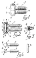
- Further characteristics and advantages of the invention will become apparent from the detailed description of an embodiment, illustrated only by way of non-limitative example in the accompanying drawings, wherein:
- figure 1 is a perspective view of a hinge according to the invention;
- figure 2 is a longitudinal sectional view of the hinge of figure 1;
- figure 3 is a transverse sectional view of the hinge of figure 1;
- figure 4 illustrates the metallic elements of the hinge of figures 1 and 2.
- With reference to the above described figures, the hinge according to the invention is generally indicated by the reference numeral 1 and is composed of two parts, respectively a first part indicated by the
reference numeral 2 and a second part indicated by the reference numeral 3. - Each
part 2, 3 comprises a metallic core adapted to perform the mechanical bearing action and a covering made of plastic material, preferably nylon, which protects the metallic core against corrosion. - In particular, each
part 2, 3, has a metallic core which is constituted by a fork-like end 4 of a threadedstem 5 for fixing to the casements. - According to the invention, the fork like
end 4 is conveniently obtained from acylindrical expansion 6 of the stem which is diametrically traversed by a U-shaped recess 7. - Still according to the invention, the extension of said U-shaped recess 7 is arranged longitudinally to the axis of the hinge 1, and the center of its rounded portion is arranged on said axis.
- Each fork-
like end 4 is covered by alayer 8 of plastic material which is applied by inserting said end in a mold and by injecting said plastic material under pressure. - The mold is conveniently provided with an insert which extends through said U-shaped recess 7 so that the
layer 8 is finally provided with anaxial recess 9 in which a cylindrical rotation pivot orpin 10 is inserted during the assembly of the hinge; saidpin 10 is thus almost completely surrounded by metal at the fork-like ends 4 of the threadedstems 5. -
Axial holes 11 may be provided during the molding operations on the top of eachpart 2 or 3 of the hinge 1, connecting the outside with each end of thepivot 10, which can thus be lubricated. - From what has been described, therefore, the two
parts 2 and 3 which constitute the hinge 1 are substantially identical and are simply associated by thepin 10 which can rotate inside both U-shaped recesses 7. - In any case, however, the
rotation pivot 10 may have annular recesses or coupling devices, and may be rigidly associated with one of the two parts during the molding step, e.g., by being partially embedded in the plastic material. - Another aspect of the invention consists in deforming the
tips 12 and 13 of the fork-like end 4 so that therecess 9 almost completely embraces thepivot 10, thereby improving the mechanical resistance of the walls of the rotation seat. - From the above description it is thus evident that the hinge is composed of three simple elements, two of which are substantially identical, since the differences arising from a male-female coupling have been eliminated.
- It is important to stress that the hinge is manufactured without welding operations, since the threaded
stems 5 are locked in the layers ofplastic material 8 by virtue of the embedding of theexpansions 6. - This allows a considerable simplification of the production steps and a considerable reduction of production times.
- Another considerable advantage resides in the fact that by eliminating the weld for connecting the threaded stem to a male or female part of the hinge, the danger of the molds being subjected to damage caused by burr or welding defects is also eliminated.
- The result is a hinge which is practically totally weather-proof, since none of its metallic parts is exposed to the atmosphere.
- The most convenient material for covering the metal parts is nylon, which has excellent corrosion-resistance characteristics as well as excellent self-lubrication characteristics.
- With respect to known hinges, the simplification of the elements of the hinge and of the production cycle required for its manufacture, allow lower production costs and consequently provide a more commercially competitive product.
- Finally, the use of plastic material as a covering allows to obtain any aesthetic form according to models related to styles or lines of various kinds.
- The colors may also consequently be chosen according to requirements.
- It should be furthermore stressed that hinges of any kind, all of which are within the scope of the protection of the present invention, may be obtained starting from the same concept of combinations of parts.
- In practice, the materials, so long as compatible to the contingent use, as well as the dimensions, may be any according to the requirements.
- Where technical features mentioned in any claim are followed by reference signs, those reference signs have been included for the sole purpose of increasing the intelligibility of the claims and accordingly such reference signs do not have any limiting effect on the scope of each element identified by way of example by such reference signs.
Claims (7)
- Hinge (1) for casements or the like, composed of two complementary elements (2, 3), each having a metallic core (5) being covered by plastic material (8) and being constituted by a fork-like end (4) of a threaded fixing stem (5), a metallic articulation pin (10) being provided which longitudinally associates said two complementary elements (2, 3), said hinge characterized in that said pin (10) has portions which are at least partially embraced by said fork-like ends (4), at least one of said ends (4) constituting a rotation seat for said pin (10).
- Hinge (1) according to claim 1, characterized in that said fork-like end (4) is obtained from a cylindrical expansion (6) of said threaded stem (5) which is diametrically traversed by a U-shaped recess (7), the center of the round portion of said recess being arranged on the axis of rotation of said hinge (1).
- Hinge (1) according to claims 1 and 2, characterized in that said expansion (6) of each stem (5) is completely embedded in said plastic material covering (8), thus locking the movement of each stem (5) with respect to said covering (8) and to the corresponding hinge element without requiring welding operations.
- Hinge according to claims 1 and 2, characterized in that a hole (11) may be provided at the top of each plastic material covering (8), said hole (11) connecting the corresponding end of said articulation pin (10) to the outside, thereby allowing its lubrication.
- Hinge according to claims 1, 2 and 3, characterized in that said articulation pin (10) may be provided with annular recesses or coupling tabs which lock it in one of said two complementary elements (2, 3), thereby preventing rotation and/or extraction of said one of said complementary elements (2, 3) with respect to said pin (10).
- Hinge according to claims 1, 2 and 3, characterized in that the tips of said fork-like ends (4) may be deformed so as to further embrace the corresponding portions of said pin (10).
- Hinge according to the preceding claims, characterized in that said plastic material (8) is injected into a mold in which said metallic cores (5) are arranged as inserts together with elements adapted to define the rotation seats of said pin (10).
Priority Applications (1)
| Application Number | Priority Date | Filing Date | Title |
|---|---|---|---|
| AT89114099T ATE81882T1 (en) | 1988-08-10 | 1989-07-31 | CORROSION RESISTANT HINGE FOR WINDOW FRAME OR SIMILAR. |
Applications Claiming Priority (2)
| Application Number | Priority Date | Filing Date | Title |
|---|---|---|---|
| IT3070588U | 1988-08-10 | ||
| IT8830705U IT217991Z2 (en) | 1988-08-10 | 1988-08-10 | HINGE FOR FIXTURES OR SIMILAR RESISTANT TO CORROSIVE AGENTS |
Publications (2)
| Publication Number | Publication Date |
|---|---|
| EP0354439A1 EP0354439A1 (en) | 1990-02-14 |
| EP0354439B1 true EP0354439B1 (en) | 1992-10-28 |
Family
ID=11231199
Family Applications (1)
| Application Number | Title | Priority Date | Filing Date |
|---|---|---|---|
| EP89114099A Expired - Lifetime EP0354439B1 (en) | 1988-08-10 | 1989-07-31 | Corrosion-resistant hinge for casements or the like |
Country Status (7)
| Country | Link |
|---|---|
| EP (1) | EP0354439B1 (en) |
| AT (1) | ATE81882T1 (en) |
| DE (1) | DE68903309T2 (en) |
| ES (1) | ES2035472T3 (en) |
| FI (1) | FI91432C (en) |
| IT (1) | IT217991Z2 (en) |
| NO (1) | NO893200L (en) |
Cited By (1)
| Publication number | Priority date | Publication date | Assignee | Title |
|---|---|---|---|---|
| EP1223290B1 (en) * | 2001-01-10 | 2004-05-12 | Kaba Gallenschütz GmbH | Revolving door arrangement |
Families Citing this family (4)
| Publication number | Priority date | Publication date | Assignee | Title |
|---|---|---|---|---|
| DE29912582U1 (en) * | 1999-07-20 | 2000-12-21 | Niemann, Hans Dieter, 50169 Kerpen | Frame part of a door or window hinge |
| FR2856720B1 (en) * | 2003-06-30 | 2007-01-05 | Tordo Belgrano Sa | INSERT FOR ARTICULATION GOUT, IN PARTICULAR FOR VANTAIL |
| FR3041018B1 (en) * | 2015-09-16 | 2017-10-13 | Guyenne Plastique | LAUNDRY GUM COMPRISING REINFORCING OVERMOLDING AND FINISHING OVERMOLDING |
| CN107605295A (en) * | 2017-09-28 | 2018-01-19 | 山东兄弟商业设施有限公司 | Transparent hinge |
Family Cites Families (2)
| Publication number | Priority date | Publication date | Assignee | Title |
|---|---|---|---|---|
| GB851630A (en) * | 1957-08-12 | 1960-10-19 | Soiron Ferdinand Von | Improvements in or relating to hinges |
| DE1792527U (en) * | 1959-04-14 | 1959-07-23 | Alfred Grass K G | TWO PIECE HINGE. |
-
1988
- 1988-08-10 IT IT8830705U patent/IT217991Z2/en active
-
1989
- 1989-07-31 AT AT89114099T patent/ATE81882T1/en active
- 1989-07-31 EP EP89114099A patent/EP0354439B1/en not_active Expired - Lifetime
- 1989-07-31 DE DE8989114099T patent/DE68903309T2/en not_active Expired - Fee Related
- 1989-07-31 ES ES198989114099T patent/ES2035472T3/en not_active Expired - Lifetime
- 1989-08-08 NO NO89893200A patent/NO893200L/en unknown
- 1989-08-10 FI FI893770A patent/FI91432C/en not_active IP Right Cessation
Cited By (1)
| Publication number | Priority date | Publication date | Assignee | Title |
|---|---|---|---|---|
| EP1223290B1 (en) * | 2001-01-10 | 2004-05-12 | Kaba Gallenschütz GmbH | Revolving door arrangement |
Also Published As
| Publication number | Publication date |
|---|---|
| DE68903309T2 (en) | 1993-03-18 |
| ES2035472T3 (en) | 1993-04-16 |
| DE68903309D1 (en) | 1992-12-03 |
| FI893770A0 (en) | 1989-08-10 |
| FI893770L (en) | 1990-02-11 |
| NO893200L (en) | 1990-02-12 |
| ATE81882T1 (en) | 1992-11-15 |
| NO893200D0 (en) | 1989-08-08 |
| IT217991Z2 (en) | 1992-03-05 |
| FI91432C (en) | 1994-06-27 |
| FI91432B (en) | 1994-03-15 |
| EP0354439A1 (en) | 1990-02-14 |
Similar Documents
| Publication | Publication Date | Title |
|---|---|---|
| US5740586A (en) | Tool handle | |
| US5375183A (en) | Overmolded alignment ferrule | |
| US5092703A (en) | Ball joint and method of manufacturing the same | |
| US4226550A (en) | Reinforced plastic yoke | |
| KR950023350A (en) | Belt connecting device molded from synthetic resin and its manufacturing method | |
| EP0354439A1 (en) | Corrosion-resistant hinge for casements or the like | |
| MXPA96002233A (en) | Composite encased ball joint | |
| US5697143A (en) | Method of manufacturing an electrofusion coupler | |
| US5377981A (en) | Figurine support rod and figurine assembly for table football | |
| US5667442A (en) | Chain link assembly body | |
| JPS58129518A (en) | Control lever | |
| US5044224A (en) | Camshaft | |
| US4320984A (en) | Arrangement for connecting two structural parts | |
| GB2367878A (en) | Cast crankshaft counterweights | |
| JPH0328564A (en) | Manufacturing method of ball returning device of ball screw nut | |
| US4658471A (en) | Hinge with no tubular portion and method of producing the same | |
| US20030108380A1 (en) | Pivot joint and method for molding same | |
| US6722633B2 (en) | Throttle body with insert-molded member | |
| KR970016526A (en) | Fastening type body and its manufacturing method | |
| JPH0674229A (en) | Spline spindle and formation thereof | |
| US4322078A (en) | Bowling pin base | |
| US6298880B1 (en) | Spool valve and manufacturing method therefor | |
| JPH0413454Y2 (en) | ||
| US11164690B2 (en) | Actuator and method for manufacturing actuator | |
| JP3210243B2 (en) | Lubrication nozzle |
Legal Events
| Date | Code | Title | Description |
|---|---|---|---|
| PUAI | Public reference made under article 153(3) epc to a published international application that has entered the european phase |
Free format text: ORIGINAL CODE: 0009012 |
|
| AK | Designated contracting states |
Kind code of ref document: A1 Designated state(s): AT BE CH DE ES FR GB GR LI NL SE |
|
| 17P | Request for examination filed |
Effective date: 19900226 |
|
| 17Q | First examination report despatched |
Effective date: 19910708 |
|
| GRAA | (expected) grant |
Free format text: ORIGINAL CODE: 0009210 |
|
| AK | Designated contracting states |
Kind code of ref document: B1 Designated state(s): AT BE CH DE ES FR GB GR LI NL SE |
|
| PG25 | Lapsed in a contracting state [announced via postgrant information from national office to epo] |
Ref country code: SE Effective date: 19921028 Ref country code: NL Effective date: 19921028 Ref country code: LI Effective date: 19921028 Ref country code: GR Free format text: LAPSE BECAUSE OF FAILURE TO SUBMIT A TRANSLATION OF THE DESCRIPTION OR TO PAY THE FEE WITHIN THE PRESCRIBED TIME-LIMIT Effective date: 19921028 Ref country code: CH Effective date: 19921028 Ref country code: AT Effective date: 19921028 |
|
| REF | Corresponds to: |
Ref document number: 81882 Country of ref document: AT Date of ref document: 19921115 Kind code of ref document: T |
|
| REF | Corresponds to: |
Ref document number: 68903309 Country of ref document: DE Date of ref document: 19921203 |
|
| ET | Fr: translation filed | ||
| REG | Reference to a national code |
Ref country code: CH Ref legal event code: PL |
|
| NLV1 | Nl: lapsed or annulled due to failure to fulfill the requirements of art. 29p and 29m of the patents act | ||
| REG | Reference to a national code |
Ref country code: ES Ref legal event code: FG2A Ref document number: 2035472 Country of ref document: ES Kind code of ref document: T3 |
|
| PLBI | Opposition filed |
Free format text: ORIGINAL CODE: 0009260 |
|
| PG25 | Lapsed in a contracting state [announced via postgrant information from national office to epo] |
Ref country code: GB Effective date: 19930731 |
|
| 26 | Opposition filed |
Opponent name: ROTO FRANK AG Effective date: 19930720 |
|
| GBPC | Gb: european patent ceased through non-payment of renewal fee |
Effective date: 19930731 |
|
| PLBN | Opposition rejected |
Free format text: ORIGINAL CODE: 0009273 |
|
| STAA | Information on the status of an ep patent application or granted ep patent |
Free format text: STATUS: OPPOSITION REJECTED |
|
| 27O | Opposition rejected |
Effective date: 19950218 |
|
| PGFP | Annual fee paid to national office [announced via postgrant information from national office to epo] |
Ref country code: ES Payment date: 20060703 Year of fee payment: 18 |
|
| PGFP | Annual fee paid to national office [announced via postgrant information from national office to epo] |
Ref country code: DE Payment date: 20060706 Year of fee payment: 18 |
|
| PGFP | Annual fee paid to national office [announced via postgrant information from national office to epo] |
Ref country code: FR Payment date: 20060713 Year of fee payment: 18 |
|
| PGFP | Annual fee paid to national office [announced via postgrant information from national office to epo] |
Ref country code: BE Payment date: 20060714 Year of fee payment: 18 |
|
| BERE | Be: lapsed |
Owner name: *OTLAV S.P.A. Effective date: 20070731 |
|
| PG25 | Lapsed in a contracting state [announced via postgrant information from national office to epo] |
Ref country code: DE Free format text: LAPSE BECAUSE OF NON-PAYMENT OF DUE FEES Effective date: 20080201 |
|
| REG | Reference to a national code |
Ref country code: FR Ref legal event code: ST Effective date: 20080331 |
|
| PG25 | Lapsed in a contracting state [announced via postgrant information from national office to epo] |
Ref country code: BE Free format text: LAPSE BECAUSE OF NON-PAYMENT OF DUE FEES Effective date: 20070731 |
|
| PG25 | Lapsed in a contracting state [announced via postgrant information from national office to epo] |
Ref country code: FR Free format text: LAPSE BECAUSE OF NON-PAYMENT OF DUE FEES Effective date: 20070731 |
|
| REG | Reference to a national code |
Ref country code: ES Ref legal event code: FD2A Effective date: 20070801 |
|
| PG25 | Lapsed in a contracting state [announced via postgrant information from national office to epo] |
Ref country code: ES Free format text: LAPSE BECAUSE OF NON-PAYMENT OF DUE FEES Effective date: 20070801 |