EP0358560B1 - Geschoss zum Neutralisieren einer Zone, insbesondere eines Flugplatzes - Google Patents
Geschoss zum Neutralisieren einer Zone, insbesondere eines Flugplatzes Download PDFInfo
- Publication number
- EP0358560B1 EP0358560B1 EP89402408A EP89402408A EP0358560B1 EP 0358560 B1 EP0358560 B1 EP 0358560B1 EP 89402408 A EP89402408 A EP 89402408A EP 89402408 A EP89402408 A EP 89402408A EP 0358560 B1 EP0358560 B1 EP 0358560B1
- Authority
- EP
- European Patent Office
- Prior art keywords
- projectile
- tube
- projectiles
- ground
- munition
- Prior art date
- Legal status (The legal status is an assumption and is not a legal conclusion. Google has not performed a legal analysis and makes no representation as to the accuracy of the status listed.)
- Expired - Lifetime
Links
- 230000003472 neutralizing effect Effects 0.000 title 1
- 238000010304 firing Methods 0.000 claims description 5
- 238000000926 separation method Methods 0.000 claims description 5
- 239000002360 explosive Substances 0.000 claims description 3
- 238000012163 sequencing technique Methods 0.000 claims description 2
- 238000000034 method Methods 0.000 claims 3
- 230000003019 stabilising effect Effects 0.000 claims 1
- 239000004570 mortar (masonry) Substances 0.000 abstract description 9
- 239000013598 vector Substances 0.000 description 12
- 238000006386 neutralization reaction Methods 0.000 description 5
- 230000003111 delayed effect Effects 0.000 description 2
- 241000497429 Obus Species 0.000 description 1
- 241001080024 Telles Species 0.000 description 1
- 230000000593 degrading effect Effects 0.000 description 1
- 229940082150 encore Drugs 0.000 description 1
- 230000001960 triggered effect Effects 0.000 description 1
Images

Classifications
-
- F—MECHANICAL ENGINEERING; LIGHTING; HEATING; WEAPONS; BLASTING
- F42—AMMUNITION; BLASTING
- F42B—EXPLOSIVE CHARGES, e.g. FOR BLASTING, FIREWORKS, AMMUNITION
- F42B23/00—Land mines ; Land torpedoes
- F42B23/10—Land mines ; Land torpedoes anti-personnel
- F42B23/16—Land mines ; Land torpedoes anti-personnel of missile type, i.e. all kinds of mines launched for detonation after ejection from ground
-
- F—MECHANICAL ENGINEERING; LIGHTING; HEATING; WEAPONS; BLASTING
- F42—AMMUNITION; BLASTING
- F42B—EXPLOSIVE CHARGES, e.g. FOR BLASTING, FIREWORKS, AMMUNITION
- F42B10/00—Means for influencing, e.g. improving, the aerodynamic properties of projectiles or missiles; Arrangements on projectiles or missiles for stabilising, steering, range-reducing, range-increasing or fall-retarding
- F42B10/02—Stabilising arrangements
- F42B10/14—Stabilising arrangements using fins spread or deployed after launch, e.g. after leaving the barrel
Definitions
- the present invention relates to a projectile for the neutralization of a predetermined area, such as an aerodrome.
- anti-runway bombs When it is desired, for example, to deactivate an aerodrome under enemy control, it is known to destroy airstrips using specific bombs called anti-runway bombs, generally degrading the runway in general, in order to prevent its use. .
- Anti-runway bombs are immediate or delayed action but, in all cases, the zone in which they are located is a fairly restricted band and well defined by the passage of the plane or the cargo ship distributing these bombs.
- a projectile capable of being dropped from an aircraft, carrying an explosive charge and intended to land on the ground.
- deployable braking means consisting of inflatable flexible pipes carrying a wing, which allow it, once on the ground, to straighten there in a vertical position.
- Document FR -A- 499 064 is also known to be an aerial mortar intended, after having been dropped from an aircraft, to fall to the ground and sink into it by its end opposite to its fins.
- the present invention relates to the neutralization of an area, such as an aerodrome, neutralization carried out by making dangerous and / or destroying all or part of the area, for example one or more runways or taxiways of aircraft, known under the Anglo-Saxon name of taxiways.
- the fins When landing, the fins form a base for the mortar tube and, under the control of the ejection means, the ammunition is ejected at a certain distance from the tube, that is to say from the initial landing point of the projectile, in a direction depending only on the orientation of the tube once placed on the ground.
- the subject of the invention is a zone neutralization projectile as defined by claim 1.
- the projectile according to the invention is for example distributed by dropping from a carrier, plane or cargo: this is what is represented by the first step (21) of FIG. 2.
- the wearer does not drop the projectiles separately, but he drops vectors, each composed of several projectiles which subsequently separate from each other as described below.
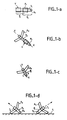
- the vector, marked V consists of two projectiles P1 and P2 nested one inside the other and fixed by any known means.
- Each projectile comprises a tube-shaped body (T1 for the P1 projectile) closed at one of its ends by a nose (N1), which contains various electrical and electronic means of sequencing, control and supply.
- N1 a nose
- A1 On the rear part (opposite the nose) of the tube (T1) are mounted fins (A1) which, in this embodiment, are deployable and initially folded and which are at least three in number.
- a munition not visible in FIG. 1a. It is held there by any known means, such as retaining clip, diaphragm, further ensuring the tightness of the tube, etc.
- the next step, 22 in FIG. 2 consists in separating the carrier vector, after dropping. This is done conventionally, for example using a parachute housed at the rear of the vector V and the opening of which is controlled by the release of the vector.
- the next step, 23 in FIG. 2 consists in deploying the fins of that of the projectiles which is located furthest behind the vector V, namely the fins A2 of the projectile P2, as shown in FIG. 1b.
- These fins have a first function which is, conventionally, to stabilize the trajectory of the vector.
- the surface of each of the fins is not parallel to the longitudinal axis XX of the vector, but forms with it a non-zero angle so as to give the vector a rotational movement around its longitudinal axis.
- the next step (24, FIG. 2) is the separation of the P1 and P2 projectiles.
- This separation can be controlled, for example, by a chronometric device or by a proximometric rocket, that is to say a device triggering the separation at a certain distance of the vector from the ground.
- the Pile projectile then continues its trajectory towards the ground as shown in FIG. 1c.
- the fins of the P1 projectile are deployed and the latter continues its own trajectory towards the ground, being likewise preferably driven in a rotational movement around its longitudinal axis.
- the angle made by the surface of the fins with the longitudinal axis is different for the two projectiles, for the reasons explained below.
- this mechanism is repeated as many times as there are projectiles to be separated, preferably starting with the separation of that of the projectiles located furthest back from nesting.
- each of the projectiles meets the ground (step 25 in Figure 2) where it is posed so that the mortar tube T makes a non-zero angle with the ground plane, the fins forming indeed a foot for the tube.
- FIG. 1d where the two projectiles P1 and P2 placed on the ground S have been shown, the tubes T1 and T2 being oriented in different directions.
- the next step (26, Figure 2) is the ejection of the ammunition contained in the tube T. This is what is represented by a dotted arrow in Figure 1d. Ejection can be either instantaneous or delayed by a predetermined period of time. variable preference from one projectile to another, either triggered by a proximity or noise sensor; one can use for example a sensor sensitive to certain types of noise, such as a propeller noise. These triggering means are contained in the nose N of the projectile.
- the last step (27, Figure 2) is the firing of the ammunition.
- the ammunition can be for example of the grenade, shell, mine, mine provided with wire type, etc ....
- the ignition can be instantaneous, during the impact of the ammunition on the ground; it can be deferred, using triggering means of the type described above for ejecting the ammunition; it can still be carried out before impact of the munition on the ground, using means of the chronometric or proximetric rocket type.
- the munitions being ejected, or likely to be ejected, at a certain distance from the initial landing point of the projectile it appears that the neutralized zone is not confused with the projectile distribution zone.
- the random orientation of the mortar tubes does not allow the effective danger area to be easily determined.
- the fact that the point of impact of the ammunition is different from that of the projectile makes it possible to make a passage (track or taxiway) dangerous while the source of the danger (the mortar tube) is not found on the passage in question; the mortar tube is then more difficult to locate, and therefore neutralizable.
- the projectile according to the invention is applicable to the neutralization of any type of zone: compulsory crossing point, zone for the deployment of enemy forces, etc. It is also thus that the projectile can be launched from the ground, the steps 21 and 22 of FIG. 2 being replaced by a launching step. It is thus also that all or part of the fins can no longer be deployable but fixed, which is simpler but penalizing in terms of space during transport.
Landscapes
- Engineering & Computer Science (AREA)
- General Engineering & Computer Science (AREA)
- Physics & Mathematics (AREA)
- Fluid Mechanics (AREA)
- Aiming, Guidance, Guns With A Light Source, Armor, Camouflage, And Targets (AREA)
- Radar Systems Or Details Thereof (AREA)
- Physical Or Chemical Processes And Apparatus (AREA)
- Preparation Of Compounds By Using Micro-Organisms (AREA)
- Hydrogenated Pyridines (AREA)
- Particle Accelerators (AREA)
- Catching Or Destruction (AREA)
- Analysing Materials By The Use Of Radiation (AREA)
Claims (12)
- Geschoß zur Neutralisierung einer Zone mit- einer Explosivladung,- Mitteln, die einen Fuß für das Geschoß bilden, wenn es sich auf dem Boden befindet,dadurch gekennzeichnet, daß das Geschoß weiter enthält:- ein Mörserrohr (T),- eine Munition, die in dem Rohr angeordnet ist und die Explosivladung enthält,- mindestens drei Flügel (A) zur Stabilisierung des Geschosses, die mit dem Rohr fest verbunden sind und die die Mittel darstellen, um für das Rohr einen Fuß zu bilden, wenn es sich auf dem Boden befindet, wobei dann das Rohr bezüglich des Bodens in einer schrägen Lage ist,- idol zum Ausstoß der Munition aus dem Rohr wenn letzteres sich auf den Boden in der oben genannten Lage befindet.
- Geschoß nach Anspruch 1, dadurch gekennzeichnet, daß die Fläche jedes Flügels (A) einen gleichen Winkel ungleich Null mit der Längsachse (XX) des Rohrs (T) bildet, wodurch dem Rohr eine Drehbewegung um seine Längsachse während seines Flugs verliehen wird.
- Geschoß nach einem der vorhergehenden Ansprüche, dadurch gekennzeichnet, daß die Flügel (A) entfaltbar sind.
- Geschoß nach einem der vorhergehenden Ansprüche, dadurch gekennzeichnet, daß die Flügel (A) an einem die Rückseite des Geschosses (P) bildenden Ende des Rohrs (T) angeordnet sind und daß das Rohr an seinem den Geschoßkopf (N) bildenden anderen Ende verschlossen ist, wobei Mittel zur Folgesteuerung, zur Steuerung und zur Speisung des Geschosses in dem Kopf angeordnet sind.
- Geschoß nach Anspruch 4, dadurch gekennzeichnet, daß die in dem Kopf (N) des Geschosses (P) angeordneten Mittel auch Mittel zum verzögerten Auslösen des Ausstoßens des Geschosses um eine vorgegebene Dauer aufweisen.
- Geschoß nach Anspruch 5, dadurch gekennzeichnet, daß die in dem Kopf (N) des Geschosses (P) angeordneten Mittel eine Näherungs- oder Geräuschsonde enthalten.
- Geschoß nach einem der vorhergehenden Ansprüche, dadurch gekennzeichnet, daß die Munition eine Granate, Mine oder mit einem Draht versehene Mine ist.
- Geschoß nach einem der vorhergehenden Ansprüche, dadurch gekennzeichnet, daß die Munition Mittel zum Auslösen der Zündung enthalten, die das Zünden der Munition vor ihrem Auftreffen auf dem Boden gewährleisten.
- Geschoß nach einem der vorhergehenden Ansprüche, dadurch gekennzeichnet, daß die Munition Mittel zum Auslösen der Zündung enthalten, die das Zünden der Munition nach dem Auftreffen auf den Boden gewährleisten.
- Verfahren zur Neutralisierung einer Zone, dadurch gekennzeichnet, daß es nacheinander folgende Schritte aufweist:- einen Schritt der Verteilung einer Gruppe von Geschossen gemäß einem der vorhergehenden Ansprüche über die Zone,- nach der Landung jedes Geschosses einen Verfahrensschritt des Ausstoßens der Munition aus ihrem Rohr.
- Verfahren nach Anspruch 10, dadurch gekennzeichnet, daß der Verfahrensschritt der Verteilung folgende Unterverfahrensschritte enthält:- Abwurf (21) der Geschosse von einem Flugzeug,- Trennung (22) der Geschosse vom Flugzeug,- Entfalten (23) der Flügel von mindestens einem Teil der Geschosse,- Landen (25) der Geschosse in der Zone.
- Raketenträger für die Neutralisierung einer Zone zur Durchführung des Verfahrens nach einem der Ansprüche 10 oder 11, dadurch gekennzeichnet, daß er mindestens zwei Geschosse (P₁, P₂) gemäß einem der Ansprüche 1 bis 9 enthält, wobei die beiden Geschosse während des Abschusses ineinandergesteckt und dann während des Flugs des Trägers (V) voneinander getrennt werden.
Priority Applications (1)
| Application Number | Priority Date | Filing Date | Title |
|---|---|---|---|
| AT89402408T ATE92177T1 (de) | 1988-09-09 | 1989-09-05 | Geschoss zum neutralisieren einer zone, insbesondere eines flugplatzes. |
Applications Claiming Priority (2)
| Application Number | Priority Date | Filing Date | Title |
|---|---|---|---|
| FR8811823 | 1988-09-09 | ||
| FR8811823A FR2636419B1 (fr) | 1988-09-09 | 1988-09-09 | Projectile de neutralisation de zone, notamment d'aerodrome |
Publications (2)
| Publication Number | Publication Date |
|---|---|
| EP0358560A1 EP0358560A1 (de) | 1990-03-14 |
| EP0358560B1 true EP0358560B1 (de) | 1993-07-28 |
Family
ID=9369875
Family Applications (1)
| Application Number | Title | Priority Date | Filing Date |
|---|---|---|---|
| EP89402408A Expired - Lifetime EP0358560B1 (de) | 1988-09-09 | 1989-09-05 | Geschoss zum Neutralisieren einer Zone, insbesondere eines Flugplatzes |
Country Status (7)
| Country | Link |
|---|---|
| US (1) | US4981079A (de) |
| EP (1) | EP0358560B1 (de) |
| AT (1) | ATE92177T1 (de) |
| DE (1) | DE68907827T2 (de) |
| FR (1) | FR2636419B1 (de) |
| IL (1) | IL91527A0 (de) |
| ZA (1) | ZA896779B (de) |
Families Citing this family (4)
| Publication number | Priority date | Publication date | Assignee | Title |
|---|---|---|---|---|
| DE4023069A1 (de) * | 1990-07-20 | 1992-01-23 | Diehl Gmbh & Co | Mine, insbes. panzerabwehrmine |
| RU2175626C2 (ru) * | 1999-12-17 | 2001-11-10 | Кириллов Андрей Порфирьевич | Летательный аппарат для поражения объекта (варианты) |
| US6543364B2 (en) * | 2001-02-15 | 2003-04-08 | Scientific Applications & Research Associates | Less lethal multi-sensory distraction grenade |
| CN102564245A (zh) * | 2012-01-17 | 2012-07-11 | 中国矿业大学 | 飞翼式手掷炸弹 |
Family Cites Families (15)
| Publication number | Priority date | Publication date | Assignee | Title |
|---|---|---|---|---|
| GB133063A (de) * | 1916-08-30 | |||
| US1289702A (en) * | 1917-02-06 | 1918-12-31 | William Draper | Dart. |
| US3175489A (en) * | 1962-11-27 | 1965-03-30 | Jr Edwin G Reed | Air-delivered anti-personnel mine |
| US3439610A (en) * | 1964-04-20 | 1969-04-22 | Us Navy | Folding munition |
| FR1605558A (en) * | 1968-09-18 | 1980-07-25 | Small ground-to-ground missile - has multiple detector including IR, seismic or magnetic sensors for guidance in triple phase trajectory | |
| US4522356A (en) * | 1973-11-12 | 1985-06-11 | General Dynamics, Pomona Division | Multiple target seeking clustered munition and system |
| US4063515A (en) * | 1976-06-11 | 1977-12-20 | Calspan Corporation | Dispersive subprojectiles for chaff cartridges |
| FR2479972A1 (fr) * | 1980-04-04 | 1981-10-09 | Pandelakis Jean Claude | Dispositif d'attaque d'objectifs destine a l'armement d'aeronefs et son procede d'utilisation |
| DE3127071C2 (de) * | 1981-07-09 | 1985-06-27 | Messerschmitt-Bölkow-Blohm GmbH, 8000 München | Abwurfkörper |
| FR2541444A1 (fr) * | 1982-06-25 | 1984-08-24 | Thomson Csf | Dispositif de detection a distance du type mine et systeme de tir comportant de tels dispositifs |
| DE3510402A1 (de) * | 1985-03-22 | 1986-09-25 | Diehl GmbH & Co, 8500 Nürnberg | Stapelbare munition |
| DE3527522A1 (de) * | 1985-08-01 | 1987-02-12 | Diehl Gmbh & Co | Verfahren und verwendung von endphasenkorrigierter submunition zum bekaempfen von gepanzerten unterstaenden |
| US4715283A (en) * | 1986-11-18 | 1987-12-29 | Science Applications International Corporation | Guided missile |
| DE3643294A1 (de) * | 1986-12-18 | 1988-06-23 | Rheinmetall Gmbh | Geschoss |
| FR2623773B1 (fr) * | 1987-11-30 | 1990-04-27 | Aerospatiale | Corps largable muni de moyens de freinage aerodynamique |
-
1988
- 1988-09-09 FR FR8811823A patent/FR2636419B1/fr not_active Expired - Fee Related
-
1989
- 1989-09-05 IL IL91527A patent/IL91527A0/xx not_active IP Right Cessation
- 1989-09-05 ZA ZA896779A patent/ZA896779B/xx unknown
- 1989-09-05 AT AT89402408T patent/ATE92177T1/de not_active IP Right Cessation
- 1989-09-05 DE DE89402408T patent/DE68907827T2/de not_active Expired - Fee Related
- 1989-09-05 US US07/403,264 patent/US4981079A/en not_active Expired - Fee Related
- 1989-09-05 EP EP89402408A patent/EP0358560B1/de not_active Expired - Lifetime
Also Published As
| Publication number | Publication date |
|---|---|
| DE68907827T2 (de) | 1993-11-04 |
| FR2636419B1 (fr) | 1993-10-01 |
| EP0358560A1 (de) | 1990-03-14 |
| ATE92177T1 (de) | 1993-08-15 |
| DE68907827D1 (de) | 1993-09-02 |
| IL91527A0 (en) | 1990-04-29 |
| US4981079A (en) | 1991-01-01 |
| FR2636419A1 (fr) | 1990-03-16 |
| ZA896779B (en) | 1990-06-27 |
Similar Documents
| Publication | Publication Date | Title |
|---|---|---|
| US5074216A (en) | Infrared signature enhancement decoy | |
| US5497156A (en) | Towed target | |
| US1488182A (en) | Ordnance projectile | |
| US5760330A (en) | Method and apparatus for conveying a large-calibre payload over an operational terrain | |
| US4372216A (en) | Dispensing system for use on a carrier missile for rearward ejection of submissiles | |
| FR2727514A1 (fr) | Procede d'ejection et de dispersion de sous-munitions, porteur de sous-munitions et sous-munitions destinees a etre utilisees pour la mise en oeuvre du procede | |
| US4178854A (en) | Multiple sequential burst system | |
| EP0358560B1 (de) | Geschoss zum Neutralisieren einer Zone, insbesondere eines Flugplatzes | |
| EP0130893B1 (de) | Trägergeschoss für Streumunition | |
| EP0910245B1 (de) | Feuerwerk zum bekämpfen von vogelgefahr | |
| US5368255A (en) | Aerotumbling missile | |
| EP0457657B1 (de) | Durchdringendes Geschoss | |
| US5198609A (en) | Auxiliary target area chaff container | |
| CA2031535A1 (fr) | Systeme d'armes automatise pour la defense de zone | |
| US5054400A (en) | Separating device for the aerodynamic braking of a body | |
| EP0918205B1 (de) | Projektil mit radialer Wirkrichtung | |
| FR2644575A1 (fr) | Marqueur d'objectif pour attirer des projectiles munis d'un autodirecteur | |
| EP0319379B1 (de) | Abwurfkörper mit aerodynamischen Bremsmitteln | |
| FR2656082A1 (fr) | Systeme deployable pour l'emport et la sustentation d'une munition. | |
| FR2769083A1 (fr) | Procede de guidage d'un missile et missile pour la mise en oeuvre du procede | |
| FR2712683A1 (fr) | Bombe de protection des avions et procédé d'utilisation. | |
| EP0421873B1 (de) | Vorrichtung zum Abbremsen von Bomben nach Abwurf aus einem Flugzeug | |
| FR2947046A1 (fr) | Tete militaire comportant des moyens de marquage de cible | |
| FR2930984A1 (fr) | Procede et munitions de contre-mesure par ecran a vision unidirectionnelle | |
| FR2523717A1 (fr) | Systeme d'arme, notamment antichar |
Legal Events
| Date | Code | Title | Description |
|---|---|---|---|
| PUAI | Public reference made under article 153(3) epc to a published international application that has entered the european phase |
Free format text: ORIGINAL CODE: 0009012 |
|
| AK | Designated contracting states |
Kind code of ref document: A1 Designated state(s): AT BE CH DE ES GB IT LI SE |
|
| 17P | Request for examination filed |
Effective date: 19900816 |
|
| 17Q | First examination report despatched |
Effective date: 19910924 |
|
| GRAA | (expected) grant |
Free format text: ORIGINAL CODE: 0009210 |
|
| AK | Designated contracting states |
Kind code of ref document: B1 Designated state(s): AT BE CH DE ES GB IT LI SE |
|
| PG25 | Lapsed in a contracting state [announced via postgrant information from national office to epo] |
Ref country code: ES Free format text: THE PATENT HAS BEEN ANNULLED BY A DECISION OF A NATIONAL AUTHORITY Effective date: 19930728 Ref country code: AT Effective date: 19930728 |
|
| REF | Corresponds to: |
Ref document number: 92177 Country of ref document: AT Date of ref document: 19930815 Kind code of ref document: T |
|
| PGFP | Annual fee paid to national office [announced via postgrant information from national office to epo] |
Ref country code: CH Payment date: 19930816 Year of fee payment: 5 |
|
| PGFP | Annual fee paid to national office [announced via postgrant information from national office to epo] |
Ref country code: SE Payment date: 19930823 Year of fee payment: 5 Ref country code: GB Payment date: 19930823 Year of fee payment: 5 |
|
| PGFP | Annual fee paid to national office [announced via postgrant information from national office to epo] |
Ref country code: DE Payment date: 19930824 Year of fee payment: 5 |
|
| ITF | It: translation for a ep patent filed | ||
| REF | Corresponds to: |
Ref document number: 68907827 Country of ref document: DE Date of ref document: 19930902 |
|
| GBT | Gb: translation of ep patent filed (gb section 77(6)(a)/1977) |
Effective date: 19930818 |
|
| PG25 | Lapsed in a contracting state [announced via postgrant information from national office to epo] |
Ref country code: BE Effective date: 19930930 |
|
| BERE | Be: lapsed |
Owner name: THOMSON-BRANDT ARMEMENTS Effective date: 19930930 |
|
| PLBE | No opposition filed within time limit |
Free format text: ORIGINAL CODE: 0009261 |
|
| STAA | Information on the status of an ep patent application or granted ep patent |
Free format text: STATUS: NO OPPOSITION FILED WITHIN TIME LIMIT |
|
| 26N | No opposition filed | ||
| PG25 | Lapsed in a contracting state [announced via postgrant information from national office to epo] |
Ref country code: GB Effective date: 19940905 |
|
| PG25 | Lapsed in a contracting state [announced via postgrant information from national office to epo] |
Ref country code: SE Effective date: 19940906 |
|
| PG25 | Lapsed in a contracting state [announced via postgrant information from national office to epo] |
Ref country code: LI Effective date: 19940930 Ref country code: CH Effective date: 19940930 |
|
| EAL | Se: european patent in force in sweden |
Ref document number: 89402408.2 |
|
| GBPC | Gb: european patent ceased through non-payment of renewal fee |
Effective date: 19940905 |
|
| REG | Reference to a national code |
Ref country code: CH Ref legal event code: PL |
|
| PG25 | Lapsed in a contracting state [announced via postgrant information from national office to epo] |
Ref country code: DE Effective date: 19950601 |
|
| EUG | Se: european patent has lapsed |
Ref document number: 89402408.2 |
|
| REG | Reference to a national code |
Ref country code: CH Ref legal event code: AUV Free format text: LE BREVET CI-DESSUS EST TOMBE EN DECHEANCE, FAUTE DE PAIEMENT, DE LA 6E ANNUITE. |
|
| PG25 | Lapsed in a contracting state [announced via postgrant information from national office to epo] |
Ref country code: IT Free format text: LAPSE BECAUSE OF NON-PAYMENT OF DUE FEES;WARNING: LAPSES OF ITALIAN PATENTS WITH EFFECTIVE DATE BEFORE 2007 MAY HAVE OCCURRED AT ANY TIME BEFORE 2007. THE CORRECT EFFECTIVE DATE MAY BE DIFFERENT FROM THE ONE RECORDED. Effective date: 20050905 |