EP0364114B1 - Überführen einer feuchten Zellulosebahn - Google Patents
Überführen einer feuchten Zellulosebahn Download PDFInfo
- Publication number
- EP0364114B1 EP0364114B1 EP89309514A EP89309514A EP0364114B1 EP 0364114 B1 EP0364114 B1 EP 0364114B1 EP 89309514 A EP89309514 A EP 89309514A EP 89309514 A EP89309514 A EP 89309514A EP 0364114 B1 EP0364114 B1 EP 0364114B1
- Authority
- EP
- European Patent Office
- Prior art keywords
- web
- roll
- nip
- press
- suction
- Prior art date
- Legal status (The legal status is an assumption and is not a legal conclusion. Google has not performed a legal analysis and makes no representation as to the accuracy of the status listed.)
- Expired - Lifetime
Links
Images


Classifications
-
- D—TEXTILES; PAPER
- D21—PAPER-MAKING; PRODUCTION OF CELLULOSE
- D21F—PAPER-MAKING MACHINES; METHODS OF PRODUCING PAPER THEREON
- D21F3/00—Press section of machines for making continuous webs of paper
- D21F3/02—Wet presses
- D21F3/04—Arrangements thereof
-
- D—TEXTILES; PAPER
- D21—PAPER-MAKING; PRODUCTION OF CELLULOSE
- D21G—CALENDERS; ACCESSORIES FOR PAPER-MAKING MACHINES
- D21G9/00—Other accessories for paper-making machines
- D21G9/0063—Devices for threading a web tail through a paper-making machine
Definitions
- the present invention relates to the transfer and support of wet cellulosic webs between two moving elements in a paper machine. More specifically, the present invention relates to the detachment of moving wet cellulosic webs from a press roll or web supporting belt to another moving element in the press section or dryer section of a paper machine.
- a suspension of cellulosic fibres referred to as a furnish
- a furnish is spread on one or more moving forming fabrics or carriers and the bulk of water drained away.
- This cellulosic web or sheet which is initially weak and wet, is transferred onto a press felt which carries it into a press nip formed by two press rolls.
- the mechanical compression between the two press rolls compacts the web and eliminates part of the water from the wet web.
- the web usually leaves the press nip adhering to one of the press rolls, and must be peeled from the roll before it can be transferred to the next section of the paper machine.
- Paper machines generally have one to four presses in the press section followed by a dryer section with heated dryer rolls, to evaporate most of the water remaining in the pressed web.
- the dry web is moistened by the application of an aqueous suspension of sizing agents. This occurs in a size press after a first drying stage, and the moist sized paper is then again transferred to a second dryer section where it is dried for a second time.
- the wet cellulosic web is usually supported by a pervious belt such as forming fabric, press felts, or dryer fabric, or by other means such as a press roll.
- a mechanical support is often unavailable during web transfer between the individual moving elements of the machine.
- the web or sheet breaking especially if it is moist and the machine operates at high speed.
- the danger of sheet breaks is sometimes reduced by the addition of chemicals or by increasing the proportion of a stronger, but more expensive, component such as chemical pump or long fibre pulp in the furnish or initial fibre mix.
- the most critical areas of sheet transfer are from the forming section to the press section, between the consecutive presses in the press section, and between the last press in the press section and the first roll in the dryer section. In all of these transfer areas, the web or sheet is still wet and thus is comparatively weak.
- Several methods have been used for transferring the sheet at these areas. In one method the sheet is pulled unsupported from one element to the next through a so-called "open draw".
- the wet sheet in the open draw is unstable at high speeds and reacts to small variations in the process, sometimes having a tendency to oscillate or flutter. An excessive sheet flutter can cause deformations and wrinkling of the web and reduce the product quality or completely break the sheet and interrupt production.
- paper machines with an open draw between the former and the first press rolls usually operate at speed below 750 metres per minute.
- the reduction of excessive sheet flutter and stabilization of the web is sometimes achieved by increasing the tension in the web.
- the tension required to peel the web and to stabilize it in the open draw transfer may, in some instances, be sufficiently great to cause a break in the web and even if it does not break, a high tension can permanently stretch the web and, therefore, make it more susceptible to breaks during the subsequent operations on the paper machine.
- This reduced extensibility is preserved even in the finished product and can lead to an increased number of paper sheet breaks during converting or printing operations.
- a pervious carrier or belt such as a forming fabric
- another pervious carrier such as a press felt
- a vacuum pick-up system to transfer the web from the former to the first press roll.
- a suction roll can only efficiently transfer a web from a pervious carrier to another pervious carrier.
- Press rolls are generally solid rolls and thus a vacuum system such as a suction roll cannot by itself initiate peeling of a web from a solid press roll or even an impervious belt. In the case of a press roll, the web normally adheres better to the smoother and less pervious surface.
- Undesirable materials which generally represent fractions of cellulosic fibres, often adhere to various paper machine rolls such as press rolls, dryers or calender rolls, and are commonly removed by so-called "doctor blades" which have sharp edges positioned in close proximity to the surfaces of the machine rolls and scrape off the web and fibres adhering to the roll.
- the web removed in this manner is generally densely crimped or creped and cannot be converted into a smooth paper. Creping of a web by a doctor blade may be applied commercially to produce soft and bulky tissue paper used primarily for hygienic products. For high bulk and softness, it is desirable that the tissue paper has regularly and densely spaced creped ridges.
- EP-A-0 254 665 web transfer apparatus for transferring a narrow or tail portion of a web from a press section to a dryer section. It is mentioned that there are devices in use for blowing the tail off the press roll and for directing it towards the dryer section. Associated problems mentioned include the long open spans between the press roll and the nip of the dryer section, and the need to blow the tail off the press roll before it contacts a removing doctor blade, and the proposal is made for reducing the length of the span between the press and dryer sections (which may be in the range of 2.44 metres to 3.05 metres).
- a transfer fabric which cooperates with the dryer fabric during the majority of the travel of the web between the press and the dryer section so that the web is supported simultaneously from both sides.
- a lead-in roll 40 is disposed adjacent to a first press roll 28.
- a doctor blade 38D is located after the press roll 28D and, in use, the tail TD of the web is detached by the doctor blade and moved by curtains of air 96, 98 (see Fig 7), which are located at some distance from the doctor blade, into a nip 104 of the dryer section, likewise at a relatively remote location from the doctor blade.
- Prior documents FR-A-1 572 200 and DE- C-234 713 and GB-A-2 158 047 disclose various systems for employing air jets or air currents for transferring detached web ends between successive portions of web treatment apparatus.
- An embodiment can be used to transfer a tail or a full width strip between a press roll or a web supporting belt to a following moving element and comprises a doctor blade to initially separate the web from the roll or carrier, an air jet that blows air in a direction opposite to the movement of the web, between the web and the roll or carrier, and a vacuum or suction roll that may have a pervious belt thereon to retain the web as it is transferred from the press roll or carrier.
- the embodiment provides a method and apparatus to transfer a fast moving web of flexible material from a surface of a first web supporting moving element to a second web supporting moving element while continuously supporting said web during the transfer thereof.
- the apparatus comprises firstly a first web supporting moving element, and secondly a suction roll in contact with said web, defining a nip with said first moving element.
- the apparatus further comprises a doctor blade in contact with said surface immediately after said nip to cause separation of said web from said surface. Additionally, there is provided means for producing an air jet adjacent said doctor blade, between said web and said surface and in a direction substantially opposite the direction of movement of said web, said air jets constituting means for supporting and guiding sad web toward said suction roll.
- a pervious belt moves through the nip, around the suction roll and the web is transferred to this pervious belt.
- the doctor blade and air jet comprise a unitary assembly with an air plenum connected to a tapered air chamber culminating in two lips with a gap between the lips forming an air jet.
- One of the two lips forming the doctor blade is positioned in contact with the surface of the roll or web supporting belt.
- the air plenum and air chamber form a unitary assembly, said assembly being movable between first and second positions, in said first position said assembly contacts the surface of the roll or web supporting belt so that the air jet therefrom is directed towards the nip formed by the press roll and suction roll, in said second position said assembly being positioned so that it is out of contact with said surface.
- a method of forming a web of fibrous sheet material including the steps of forming a wet web of cellulosic fibres, moving the web through a press section having a plurality of press rolls to a dryer section, the improvement of transferring the moving web from a press roll to a following moving element, comprising the steps of: feeding the moving web around the press roll through a nip formed between the press roll and a suction roll, detaching the moving web from the press roll immediately after the nip by a combination of a doctor blade and blowing a jet of air in a direction counter to the moving web between the press roll and the web, and guiding and supporting the moving web to the following moving element by a combination of the air jet and suction from the suction roll.
- FIG 1 illustrates a solid roll 10, which is the last roll in a press section of a paper machine, with a web 12 of wet cellulosic fibres moving on the roll 10 from a nip 14 with the previous press roll 16.
- a suction roll 18 forms a nip 19 with the solid roll 10, and a pervious belt 20, in the form of fabric belt, moves around the suction roll 18 and through the nip 19.
- a second carrier belt 22, which is also pervious, is conveyed about a further roll 24 positioned beneath the suction roll 18 to provide a passage for the web 12 between the first carrier belt 20 and the second carrier belt 22.
- the suction roll 18 is to provide suction to separate the web 12 from the surface of the solid roll 10 and direct it between the carrier belts. However, because the solid roll 10 does not allow air to pass therethrough, the suction roll 18 has little effect in separating the web 12 from the solid roll 10. As can be seen in FIG 1, the web 12 passes down to a conventional doctor blade 26 which separates the web 12 and crimps or crepes the web as it is separated from the roll 10. FIG 1 illustrates a prior art arrangement which is not considered satisfactory.
- FIG 2 A doctor blade and air jet assembly 30 are shown in FIG 2 which comprises an air plenum 32 in the form of a pipe with a slot or a series of holes 34. Air passes into an air chamber 36 formed by two tapered walls 38 which taper down to a first lip 40 and a second lip 42.
- FIG 2 shows the first lip 40 representing a doctor blade in contact with the surface of a press roll 10 so that the web 12 is shown to separate adjacent the doctor blade lip 40.
- the second lip 42 is shown to extend not so far as the first lip 40 and a gap 44 or slit between the two lips 40 and 42 provides a longitudinal air jet to eject a flat jet of air.
- jet has been used throughout the specification, this terminology includes a longitudinal stream of air as would be ejected by a gap or slit 44.
- FIG 3 shows one embodiment of an air chamber 36 wherein the tapered walls 38 join to a first lip 40 and a second lip 42 which converge inwards to the gap 44 at the ends of the lips 40 and 42.
- FIG 4 shows another embodiment wherein the two lips 40 and 42 are parallel to each other, thus the gap 44 represents a parallel gap and provides a flat jet of air therefrom.
- FIGS 5, 6 and 7 represent different tips of the doctor blade lip 40.
- the contact angle alpha as shown in FIG 5 being similar to that used on conventional blades wherein the edge of the blade scrapes the roll surface.
- One or both lips of the assembly may be replaced if the lip or lips are damaged or worn.
- the optimum gap width depends on production parameters such as machine speed, product grade, web adhesive force etc.
- the gap width between the two lips may be between 0.1 and 3.0 mm wide, and preferably is in the approximate range of 0.3 to 0.8 mm.
- FIG 8 shows a suction roll 18 positioned above the doctor blade and air jet assembly 30.
- the assembly 30 In the initial phase of the start-up procedure, the assembly 30 is in position A and the leading edge of the tail or full machine width of web 12 is detached from the roll 10 by impact with lip 40 of the doctor blade.
- the web 10 is then forced by the air jet towards the suction roll 18 and is attracted to the roll surface by the vacuum within the suction roll 18.
- the web 12 is thus transferred to the felt 20.
- the assembly 30 is no longer required and is switched to position B and the air supply shut off. If a web break occurs, the web is rethreaded with the assembly 30 in position A. During an operating period of anticipated web breaks, the assembly is left in position A.
- the suction roll 18 is shown having three zones.
- the first zone 50 located nearest to the nip 19, has a high vacuum level to assist in establishing the initial contact between the web 12 and the felt covered suction roll 18.
- the second zone 52 downstream from the first zone 50 is a larger zone and acts as a holding zone with a lower vacuum level.
- the first zone 50 may have a vacuum level in the range of about 10 to 80 kPa and the second zone 52 has a vacuum level in the range of from 0 to 50 kPa.
- the second zone 52 is sufficient to maintain and support the web 12 on the felt 20.
- the third zone 54 provides a small positive air pressure to ensure that the web 12 is easily parted from the felt 20 as the felt 20 separates from the suction roll 18.
- the air pressure in the air plenum 32 depends on production variables such as doctor gap, width, machine speed, product grade and the web adhesion to the roll, but preferably ranges from about 14 kPa to 600 kPa.
- the most convenient air pressure for an air blade with a gap width of 0.5 mm was found to be between 34 kPa and 100 kPa.
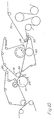
- FIG 9 illustrates the transfer system of the present invention used to transfer the web from the plain roll 10 of the last press which is the central roll of a three-roll inclined press.
- FIG 10 illustrates two transfer systems, the second of which transfers from a pervious or impermeable web supporting belt 60 onto a dryer felt 70.
- the device could be used for the transfer of various flexible thin materials and is particularly suitable for the transfer of weak and extensible sheets such as wet paper or paperboard, dry creped hygienic paper or non-woven products.
- a pilot paper machine was used to make paper in two different ways. Paper was first made with a direct transfer from the press section using the air doctor transfer roll arrangement of the present invention, and secondly, paper was transferred from the solid roll using the conventional open draw operation. The tensile properties of the paper so made were then compared.
- the pilot machine consisted of a roll former with a suction pick-up, a three-roll inclined press and a sampler as illustrated in FIG 9.
- the transfer system was installed between the second press nip and the sampler as shown in FIG 9.
- the paper machine was producing a web 0.33 meters wide with a basis weight of about 50 grams per square meter at 800 meters per minute using a newsprint furnish.
- the first and second press nip loads were 60 and 120 kN/m respectively, and the solid content of the paper after the second press was approximately 42%.
- the wet paper used for the laboratory test was reeled with minimum draw (less than 1%) for the air doctor transfer roll experiments and at several draws between 2 and 4% for the open draw experiments.
- the experimental results are shown in the following table.
- the wet stretch measurements were done on samples cut from the reel (2.5 x 10 centimetres) sealed in a bag, and handled in such a way to reduce moisture loss. Other samples were dried between blotters in a photographic dryer and cut in strips (1.5 x 10 centimetres). Both wet and dry samples were strained at 100 mm per minute in a laboratory tensile strength tester. The measurements on both the wet and dry paper demonstrate that the paper produced with a transfer arrangement according to the present invention had more stretch than that produced using the open draw system. These results indicate that the paper is less likely to break in subsequent open draws on the paper machine and in the converting or printing process.
- the transfer system described and claimed herein is capable of transferring weak wet webs, such as those made from 100% mechanical pulps. In the past, this has not been possible without forfeiting speed or having to add a percentage of chemical pulps. Thus the present invention permits the manufacture of paper from weaker and less expensive starting materials.
- the number of web breaks is reduced and the speed of the paper machine can be increased above the highest speeds of conventional machines, in the order of about 1,400 metres per minute.
- FIG 9 shows only a single transfer system, multiple transfer assemblies may be provided at different locations on the machine.
Landscapes
- Paper (AREA)
- Advancing Webs (AREA)
Claims (12)
- Verfahren, eine Bahn (12) aus faserigem Papierbogenmaterial zu formen, welche die Schritte einschließt, eine nasse Bahn von Zellulosefasern zu formen, die Bahn durch einen Preßabschnitt mit einer Vielzahl von Preßwalzen zu einem Trocknerabschnitt zu bewegen, wobei das Verfahren umfaßt die Überleitung der sich bewegenden Bahn von einer Preßwalze (10) zu einem nachfolgenden sich bewegenden Element, das Verfahren weiterhin die Schritte umfaßt:a) Beschicken der sich bewegenden Bahn (12) zwischen die Preßwalze (10) und eine Saugwalze (18);b) Ablösen der sich bewegenden Bahn von der Preßwalze unter Einsatz einer Schaberklinge (18);dadurch gekennzeichnet, daßc) die Saugwalze (18) mit der Preßwalze zusammenwirkt, um einen Spalt (19) zu umgrenzen, wobei der Spalt auf einer Seite durch eine feste Oberfläche der Preßwalze (10) und auf der anderen Seite durch die Saugwalze (18) begrenzt wird;d) die Schaberklinge (40) dicht an den Spalt (19) gesetzt wird, und eine Luftstromvorrichtung (30) Luft direkt an die Führungskante der Klinge leitet und in einer Richtung direkt in den Spalt (19) und im wesentlichen entgegengesetzt zu der Bewegungsrichtung der Bahn auf die Führungskante zu von dem Spalt her, und der Luftstrom dazu dient, in Kombination mit der Saugwalze die Bahn in dem Spalt (19) von der Preßwalze zur Saugwalze überzuleiten.
- Verfahren nach Anspruch 1, gekennzeichnet durch Veranlassen der Saugwalze (18), ein Maximum an Saugkraft an die Bahn (12) anzulegen in einem Gebiet (50) der Walze am Scheitel des Spaltes (19).
- Vorrichtung für den Transfer einer nassen Bahn (12) von Zellulosefasern von einer Preßwalze (10) zu einer Saugwalze (18), wobei die Vorrichtung umfaßt:a) die Preßwalze (10) und die Saugwalze (18), die so montiert sind, daß die Bahn (12) dazwischen beschickt werden kann;b) eine Schaberklinge (40, 42), um die Bahn (12) von der Preßwalze (10) zu lösendadurch gekennzeichnet, daßc) die Saugwalze (18) mit der Preßwalze (10) zusammenwirkt, um einen Spalt (19) zu begrenzen, der an der einen Seite eine feste Oberfläche der Preßwalze hat und an der anderen Seite die Saugwalze;d) die Schaberklinge (40, 42) dicht an dem Spalt (19) angebracht ist, und eine Luftstromvorrichtung vorgesehen ist, um Luft direkt auf die Führungskante der Schaberklinge zu liefern und in einer Richtung direkt in den Spalt (19) und im wesentlichen entgegengesetzt zu der Bewegungsrichtung der Bahn zu der Führungskante, von dem Spalt, und die Luftstromvorrichtung in Verbindung mit der Saugwalze dazu dient, die Bahn in dem Spalt von der Preßwalze zu der Saugwalze überzuleiten.
- Vorrichtung nach Anspruch 3, gekennzeichnet durch die Saugwalze (18) mit einer Region (50), die am Scheitel des Spalts (19) liegt, an dem ein Maximum an Saugkraft angelegt wird, und einer Region (52) in Abstand davon, an die eine verminderte Saugkraft angelegt wird.
- Vorrichtung nach Anspruch 3 oder 4, gekennzeichnet durch die Luftstromvorrichtung (30), welche ein Luftverteilergehäuse (32) enthält, das mit einer sich verjüngenden Luftspeicherkammer verbunden ist, die zu zwei Lippen (40, 42) führt mit einer Öffnung (44) zwischen den Lippen, die die Luftdüse bilden, wobei eine der Lippen die Schaberklinge bildet.
- Vorrichtung nach Anspruch 5, dadurch gekennzeichnet, daß die zwei Lippen (40, 42) dieselbe Länge haben.
- Vorrichung nach Anspruch 5, dadurch gekennzeichnet, daß eine der zwei Lippen länger ist als die andere Lippe.
- Vorrichtung nach Anspruch 5, dadurch gekennzeichnet, daß benachbarte Wände der zwei Lippen (40, 42) zu der Öffnung (44) konvergieren.
- Vorrichtung nach Anspruch 5, dadurch gekennzeichnet, daß benachbarte Wände der zwei Lippen (40, 42) vor der Öffnung (44) parallel sind.
- Vorrichtung nach Anspruch 5, dadurch gekennzeichnet, daß die Breite der Öffnung, die die Luftdüse bildet, in dem annähernden Bereich von 0.1 bis 3.0 mm ist.
- Vorrichtung nach Anspruch 10, dadurch gekennzeichnet, daß die Luftstromvorrichtung (30) ein Mittel umfaßt, um in dem Luftverteilergehäuse einen Druck in dem annähernden Bereich von 14 bis 600 kPa aufzubauen.
- Vorrichtung nach einem der vorhergehenden Ansprüche, dadurch gekennzeichnet, daß die Luftstromvorrichtung (30) zwischen einer ersten und zweiten Position beweglich ist, in der sie die Oberfläche der Preßwalze berührt bzw. Abstand von ihr hat.
Applications Claiming Priority (2)
| Application Number | Priority Date | Filing Date | Title |
|---|---|---|---|
| US25084088A | 1988-09-29 | 1988-09-29 | |
| US250840 | 1988-09-29 |
Publications (2)
| Publication Number | Publication Date |
|---|---|
| EP0364114A1 EP0364114A1 (de) | 1990-04-18 |
| EP0364114B1 true EP0364114B1 (de) | 1993-12-15 |
Family
ID=22949376
Family Applications (1)
| Application Number | Title | Priority Date | Filing Date |
|---|---|---|---|
| EP89309514A Expired - Lifetime EP0364114B1 (de) | 1988-09-29 | 1989-09-19 | Überführen einer feuchten Zellulosebahn |
Country Status (7)
| Country | Link |
|---|---|
| EP (1) | EP0364114B1 (de) |
| JP (1) | JP2612942B2 (de) |
| BR (1) | BR8904879A (de) |
| CA (1) | CA1321093C (de) |
| DE (1) | DE68911462T2 (de) |
| ES (1) | ES2047128T3 (de) |
| FI (1) | FI93035C (de) |
Families Citing this family (8)
| Publication number | Priority date | Publication date | Assignee | Title |
|---|---|---|---|---|
| FI86900C (fi) * | 1990-10-01 | 1992-10-26 | Valmet Paper Machinery Inc | Foerfarande och anordning vid spetsdragning av en pappersbana i maongcylindertorken av en pappersmaskin |
| US5665206A (en) * | 1991-01-18 | 1997-09-09 | Valmet Corporation | Method and device in a press section of a paper machine for detaching a web from a face of a press roll |
| DE4116222A1 (de) * | 1991-05-17 | 1992-11-19 | Voith Gmbh J M | Bahnabnahme-vorrichtung |
| FI108054B (fi) * | 1994-05-31 | 2001-11-15 | Metso Paper Inc | Menetelmä paperirainan kulun stabiloimiseksi paperinjohtotelan yhteydessä erityisesti puristinosan ja kuivatusosan välillä ja laite menetelmän toteuttamiseksi |
| DE10004369A1 (de) | 2000-02-02 | 2001-08-09 | Voith Paper Patent Gmbh | Überführung eines Einführstreifens einer Papierbahn |
| FI114935B (fi) | 2000-06-09 | 2005-01-31 | Metso Paper Inc | Menetelmä ja järjestelmä paperikoneessa tai vastaavassa rainan siirtämiseksi puristinosalta kuivatusosalle |
| US8337667B2 (en) * | 2009-01-23 | 2012-12-25 | Kadant, Inc. | Systems and methods for providing improved dewatering performance in a papermaking machine |
| CN112140686B (zh) * | 2020-09-18 | 2021-06-11 | 吉林中维科环境科技有限公司 | 一种防水纸塑复合布制造复合加工工艺 |
Citations (1)
| Publication number | Priority date | Publication date | Assignee | Title |
|---|---|---|---|---|
| EP0254665A1 (de) * | 1986-07-18 | 1988-01-27 | Beloit Corporation | Vorrichtung zum Überführen von Bahnen |
Family Cites Families (4)
| Publication number | Priority date | Publication date | Assignee | Title |
|---|---|---|---|---|
| DE234713C (de) * | ||||
| FR1572200A (de) * | 1968-01-05 | 1969-06-27 | ||
| FI67901C (fi) * | 1983-10-03 | 1987-07-20 | Valmet Oy | Foerfarande och anordning i torkpartiet i en pappersmaskin vid styrning av banans spets. |
| FI69144C (fi) * | 1984-05-04 | 1985-12-10 | Valmet Oy | Anordning i en pappersmaskin vid styrningen av banans spetsdragningsband |
-
1989
- 1989-09-19 DE DE89309514T patent/DE68911462T2/de not_active Expired - Lifetime
- 1989-09-19 ES ES89309514T patent/ES2047128T3/es not_active Expired - Lifetime
- 1989-09-19 EP EP89309514A patent/EP0364114B1/de not_active Expired - Lifetime
- 1989-09-26 BR BR898904879A patent/BR8904879A/pt not_active IP Right Cessation
- 1989-09-28 FI FI894609A patent/FI93035C/fi not_active IP Right Cessation
- 1989-09-28 JP JP1253704A patent/JP2612942B2/ja not_active Expired - Lifetime
- 1989-09-29 CA CA000615012A patent/CA1321093C/en not_active Expired - Lifetime
Patent Citations (1)
| Publication number | Priority date | Publication date | Assignee | Title |
|---|---|---|---|---|
| EP0254665A1 (de) * | 1986-07-18 | 1988-01-27 | Beloit Corporation | Vorrichtung zum Überführen von Bahnen |
Also Published As
| Publication number | Publication date |
|---|---|
| JPH02132049A (ja) | 1990-05-21 |
| FI894609A7 (fi) | 1990-03-30 |
| ES2047128T3 (es) | 1994-02-16 |
| FI93035C (fi) | 1995-02-10 |
| DE68911462T2 (de) | 1994-04-28 |
| FI93035B (fi) | 1994-10-31 |
| CA1321093C (en) | 1993-08-10 |
| EP0364114A1 (de) | 1990-04-18 |
| FI894609A0 (fi) | 1989-09-28 |
| JP2612942B2 (ja) | 1997-05-21 |
| BR8904879A (pt) | 1990-05-08 |
| DE68911462D1 (de) | 1994-01-27 |
Similar Documents
| Publication | Publication Date | Title |
|---|---|---|
| US5232555A (en) | Wet cellulosic web transfer method using air doctor blade | |
| US3981084A (en) | Closed draw transfer system with gaseous pressure direction of web | |
| US5762759A (en) | Tail threading system for a papermaking machine | |
| AU656363B2 (en) | Manufacture of a dry web of paper | |
| US3531371A (en) | Apparatus for making paper | |
| EP0438388A1 (de) | Vorrichtung zum halten der kanten einer bahn an einem trocknerfilz. | |
| EP0364114B1 (de) | Überführen einer feuchten Zellulosebahn | |
| EP1122361B1 (de) | Überführen einer Aufführspitze einer Papierbahn | |
| JP3518867B2 (ja) | 紙ウェブコーティングライン用組立体 | |
| EP0584492B1 (de) | Papiermaschine mit einem Einfädelsystem in der Presspartie | |
| CA2216048C (en) | Papermaking dryer section with partitioned vacuum box for threading | |
| US2686463A (en) | Automatic deckle edge separating press roll section | |
| CA1242075A (en) | Method and apparatus for reducing the energy consumption when drying a paper web | |
| US4081320A (en) | Method and apparatus for separating a fibrous web from a foraminous belt | |
| EP0483183B1 (de) | Verfahren und vorrichtung zur herstellung von glattem und glänzendem papier | |
| JP2000256982A (ja) | 抄紙機におけるテール紙の通紙方法とその装置 | |
| US3758380A (en) | Paper machine couching box with a multiperforate surface | |
| US6413375B2 (en) | Paper machine | |
| CA2176956A1 (en) | Threading vacuum sheave for a tissue calender | |
| CA3136864C (en) | Device and method for transferring the tail of a web | |
| McDonald et al. | A new web transfer system for closing the draw between the last press and the dryer section | |
| US20040129399A1 (en) | Device for detaching a paper web from a wire | |
| CN101139807A (zh) | 湿纸幅的平滑方法和用于造纸机的压榨部 |
Legal Events
| Date | Code | Title | Description |
|---|---|---|---|
| PUAI | Public reference made under article 153(3) epc to a published international application that has entered the european phase |
Free format text: ORIGINAL CODE: 0009012 |
|
| AK | Designated contracting states |
Kind code of ref document: A1 Designated state(s): DE ES FR GB IT SE |
|
| 17P | Request for examination filed |
Effective date: 19900509 |
|
| 17Q | First examination report despatched |
Effective date: 19910809 |
|
| ITF | It: translation for a ep patent filed | ||
| GRAA | (expected) grant |
Free format text: ORIGINAL CODE: 0009210 |
|
| AK | Designated contracting states |
Kind code of ref document: B1 Designated state(s): DE ES FR GB IT SE |
|
| REF | Corresponds to: |
Ref document number: 68911462 Country of ref document: DE Date of ref document: 19940127 |
|
| REG | Reference to a national code |
Ref country code: ES Ref legal event code: FG2A Ref document number: 2047128 Country of ref document: ES Kind code of ref document: T3 |
|
| ET | Fr: translation filed | ||
| PLBE | No opposition filed within time limit |
Free format text: ORIGINAL CODE: 0009261 |
|
| STAA | Information on the status of an ep patent application or granted ep patent |
Free format text: STATUS: NO OPPOSITION FILED WITHIN TIME LIMIT |
|
| 26N | No opposition filed | ||
| EAL | Se: european patent in force in sweden |
Ref document number: 89309514.1 |
|
| PGFP | Annual fee paid to national office [announced via postgrant information from national office to epo] |
Ref country code: SE Payment date: 19980904 Year of fee payment: 10 |
|
| PGFP | Annual fee paid to national office [announced via postgrant information from national office to epo] |
Ref country code: FR Payment date: 19980909 Year of fee payment: 10 |
|
| PGFP | Annual fee paid to national office [announced via postgrant information from national office to epo] |
Ref country code: GB Payment date: 19980914 Year of fee payment: 10 |
|
| PGFP | Annual fee paid to national office [announced via postgrant information from national office to epo] |
Ref country code: ES Payment date: 19980921 Year of fee payment: 10 |
|
| PG25 | Lapsed in a contracting state [announced via postgrant information from national office to epo] |
Ref country code: GB Free format text: LAPSE BECAUSE OF NON-PAYMENT OF DUE FEES Effective date: 19990919 |
|
| PG25 | Lapsed in a contracting state [announced via postgrant information from national office to epo] |
Ref country code: ES Free format text: LAPSE BECAUSE OF NON-PAYMENT OF DUE FEES Effective date: 19990920 |
|
| PG25 | Lapsed in a contracting state [announced via postgrant information from national office to epo] |
Ref country code: SE Free format text: THE PATENT HAS BEEN ANNULLED BY A DECISION OF A NATIONAL AUTHORITY Effective date: 19990929 |
|
| GBPC | Gb: european patent ceased through non-payment of renewal fee |
Effective date: 19990919 |
|
| EUG | Se: european patent has lapsed |
Ref document number: 89309514.1 |
|
| PG25 | Lapsed in a contracting state [announced via postgrant information from national office to epo] |
Ref country code: FR Free format text: LAPSE BECAUSE OF NON-PAYMENT OF DUE FEES Effective date: 20000531 |
|
| REG | Reference to a national code |
Ref country code: FR Ref legal event code: ST |
|
| REG | Reference to a national code |
Ref country code: GB Ref legal event code: 728V |
|
| REG | Reference to a national code |
Ref country code: GB Ref legal event code: 7281 |
|
| REG | Reference to a national code |
Ref country code: ES Ref legal event code: FD2A Effective date: 20001013 |
|
| PG25 | Lapsed in a contracting state [announced via postgrant information from national office to epo] |
Ref country code: IT Free format text: LAPSE BECAUSE OF NON-PAYMENT OF DUE FEES Effective date: 20050919 |
|
| PGFP | Annual fee paid to national office [announced via postgrant information from national office to epo] |
Ref country code: DE Payment date: 20081002 Year of fee payment: 20 |