EP0367857A1 - Vorrichtung zum lösbar gelenkigen Verbinden von tafelförmigen Wandelmenten - Google Patents
Vorrichtung zum lösbar gelenkigen Verbinden von tafelförmigen Wandelmenten Download PDFInfo
- Publication number
- EP0367857A1 EP0367857A1 EP88118736A EP88118736A EP0367857A1 EP 0367857 A1 EP0367857 A1 EP 0367857A1 EP 88118736 A EP88118736 A EP 88118736A EP 88118736 A EP88118736 A EP 88118736A EP 0367857 A1 EP0367857 A1 EP 0367857A1
- Authority
- EP
- European Patent Office
- Prior art keywords
- wall elements
- axes
- hinge axes
- sleeve body
- elements
- Prior art date
- Legal status (The legal status is an assumption and is not a legal conclusion. Google has not performed a legal analysis and makes no representation as to the accuracy of the status listed.)
- Granted
Links
- 230000008878 coupling Effects 0.000 claims abstract description 29
- 238000010168 coupling process Methods 0.000 claims abstract description 29
- 238000005859 coupling reaction Methods 0.000 claims abstract description 29
- 238000004026 adhesive bonding Methods 0.000 claims description 5
- 238000003780 insertion Methods 0.000 claims description 4
- 230000037431 insertion Effects 0.000 claims description 4
- 238000013459 approach Methods 0.000 claims description 3
- 239000000463 material Substances 0.000 description 3
- 239000004033 plastic Substances 0.000 description 3
- XEEYBQQBJWHFJM-UHFFFAOYSA-N Iron Chemical compound [Fe] XEEYBQQBJWHFJM-UHFFFAOYSA-N 0.000 description 2
- 230000015572 biosynthetic process Effects 0.000 description 2
- 238000007688 edging Methods 0.000 description 2
- 238000005755 formation reaction Methods 0.000 description 2
- 238000004519 manufacturing process Methods 0.000 description 2
- 239000011343 solid material Substances 0.000 description 2
- 239000011093 chipboard Substances 0.000 description 1
- 238000009434 installation Methods 0.000 description 1
- 229910052742 iron Inorganic materials 0.000 description 1
- 239000007769 metal material Substances 0.000 description 1
- 238000003892 spreading Methods 0.000 description 1
- 238000003860 storage Methods 0.000 description 1
- 239000002023 wood Substances 0.000 description 1
Images
Classifications
-
- E—FIXED CONSTRUCTIONS
- E04—BUILDING
- E04B—GENERAL BUILDING CONSTRUCTIONS; WALLS, e.g. PARTITIONS; ROOFS; FLOORS; CEILINGS; INSULATION OR OTHER PROTECTION OF BUILDINGS
- E04B2/00—Walls, e.g. partitions, for buildings; Wall construction with regard to insulation; Connections specially adapted to walls
- E04B2/74—Removable non-load-bearing partitions; Partitions with a free upper edge
- E04B2/7401—Removable non-load-bearing partitions; Partitions with a free upper edge assembled using panels without a frame or supporting posts, with or without upper or lower edge locating rails
- E04B2/7405—Removable non-load-bearing partitions; Partitions with a free upper edge assembled using panels without a frame or supporting posts, with or without upper or lower edge locating rails with free upper edge, e.g. for use as office space dividers
-
- E—FIXED CONSTRUCTIONS
- E04—BUILDING
- E04B—GENERAL BUILDING CONSTRUCTIONS; WALLS, e.g. PARTITIONS; ROOFS; FLOORS; CEILINGS; INSULATION OR OTHER PROTECTION OF BUILDINGS
- E04B2/00—Walls, e.g. partitions, for buildings; Wall construction with regard to insulation; Connections specially adapted to walls
- E04B2/74—Removable non-load-bearing partitions; Partitions with a free upper edge
- E04B2/7407—Removable non-load-bearing partitions; Partitions with a free upper edge assembled using frames with infill panels or coverings only; made-up of panels and a support structure incorporating posts
- E04B2/7416—Removable non-load-bearing partitions; Partitions with a free upper edge assembled using frames with infill panels or coverings only; made-up of panels and a support structure incorporating posts with free upper edge, e.g. for use as office space dividers
- E04B2/7422—Removable non-load-bearing partitions; Partitions with a free upper edge assembled using frames with infill panels or coverings only; made-up of panels and a support structure incorporating posts with free upper edge, e.g. for use as office space dividers with separate framed panels without intermediary support posts
- E04B2/7427—Removable non-load-bearing partitions; Partitions with a free upper edge assembled using frames with infill panels or coverings only; made-up of panels and a support structure incorporating posts with free upper edge, e.g. for use as office space dividers with separate framed panels without intermediary support posts with adjustable angular connection of panels
- E04B2/7431—Removable non-load-bearing partitions; Partitions with a free upper edge assembled using frames with infill panels or coverings only; made-up of panels and a support structure incorporating posts with free upper edge, e.g. for use as office space dividers with separate framed panels without intermediary support posts with adjustable angular connection of panels using hinges having two parallel rotation axes
Definitions
- the invention relates to a device for the releasably articulated connection of panel-shaped wall elements, in particular multi-layer panels with connecting elements which can be inserted in the end face of the wall elements and which pivotally engage in articulated axes formed on adjacent wall elements with articulated axes which are connected next to one another at a fixed spacing.
- this object is achieved by cylindrical sleeve bodies arranged in parallel at a distance from the longitudinal edge edges in the end faces of the wall elements and slidably and rotatably engaging in the sleeve bodies and articulated axes connected to one another at a distance by coupling elements.
- the sleeve bodies are expediently fixed in the holes in the wall elements by clamping tension. It is also possible to fix the sleeve body by gluing in the holes in the wall elements.
- the device allows the sleeve bodies to be inserted into the wall elements with any distance from the longitudinal edge edges, taking into account the strength properties of the respective wall elements, whereby any transverse forces are safely absorbed by the wall elements in order to prevent breakouts, spreading or unintentional loosening of the device.
- the device can be arranged with the same sleeve bodies in differently thick wall elements made of any materials. It is conceivable to design the sleeve bodies equally, for example in multi-layer panels or in solid material panels such as chipboard, wood or plastic panels.
- the sleeve bodies do not require complicated compliance with tolerances for any fastening layers of multi-layer wall elements. Furthermore, there is no need for complicated adhesions, as a result of which the device is easy to manufacture and to handle.
- the coupling elements and the associated joint axes are formed by a common molded part.
- the simplest molded part is an essentially U-shaped round rod, e.g. made of iron material conceivable. It is also provided to use molded parts with at least two joint axes arranged parallel and at a distance apart. The number of articulated axes depends on the number of wall elements to be connected at the same time in the area of the nodes.
- Flat strip or plate parts with recesses for receiving and fixing the joint axes can preferably serve as coupling elements.
- the recesses are expediently provided with a fold in which the joint axes can be supported and / or supported and fixed with projections projecting over the circumferential surface of the same.
- the approaches can or the like by integrally formed on the hinge axes. be educated.
- a particularly simple, flexible support can be achieved if the lugs are formed by O-rings guided in the annular grooves of the joint axes.
- the O-rings create a frictional connection and equal tolerances between the joint axes and coupling elements.
- the joint axes have O-rings guided in the grooves engaging in the sections engaging in the sleeve bodies, and that the joint axes can be released and fixed in the sleeve bodies by deformation of the O-rings.
- a limitation of the insertion depth of the hinge axes can also be achieved if the sleeve bodies have at least one partially circumferential collar on the inside as an abutment for the hinge axes. It goes without saying that collar sections can also support the joint axes.
- the invention further provides measures to compensate for unevenness in the wall when the wall elements are set up in such a way that the sleeve bodies firmly or displaceably receive these cylinder bodies which can be supported with a collar and that bolts engage in the cylinder bodies and / or the collars so as to be adjustable via axial curves and that the bolts have tiltable and rotatable support plates at the free ends. Screw threads are easily conceivable as axial curves
- the arrangement of the sleeve bodies as essential parts of the device makes it possible to cover the end faces of the wall elements in a manner fixed to the wall elements by edge strips provided with through openings for the sleeve bodies.
- the remaining wall element sections next to the sleeve bodies are large enough to securely connect the edge band, e.g. to make possible by gluing.
- the mutually facing longitudinal sides of the wall elements can be designed in any way. So there is the possibility to limit the wall elements in these areas angular or circular arc. Any cross-sectional shapes for the longitudinal edge surfaces of the wall elements, which can also be formed by edging, are also conceivable in some other way.
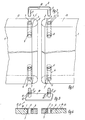
- Fig. 1 denotes wall elements which e.g. are made of solid material.
- the wall elements 1 are attached by gluing in cross-section in the form of a semicircular cross-section.
- bores 4 are made in the end faces 13 of the wall elements 1, which serve to accommodate cylindrical sleeve bodies 5.
- the sleeve body 5 are made of any material, e.g. made of a plastic or metallic material.
- the sleeve body 5 is provided with an insertion cone 6.
- connecting members 8 can be introduced, which result in a pivotably articulated connection of the wall elements 1 to one another.
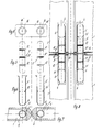
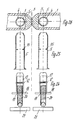
- FIG. 2 shows the simplest embodiment of a connecting member 8 made of a U-shaped round rod, with 9 articulated axes are designated, which are firmly connected to each other by a coupling member 10.
- two hinge axes 9 are arranged axially parallel and at a distance from one another on a plate-shaped coupling element 10.
- a connection of the two wall elements 1 can be achieved by inserting the joint axes 9 into the central openings 7 of the sleeve bodies 5.
- the hinge axes 9 have in the insertable into the sleeve body sections 9 'annular grooves 11 for receiving O-rings 12, which result in a frictional fixation of the hinge axes 9 in the sleeve bodies 5.
- the O-rings are the same 12 manufacturing tolerances.
- the joint axes 9 of FIGS. 5 and 8 each have a further O-ring 12 'in the central section, which fixes the joint axes 9 in the coupling elements 10.
- the sleeve bodies 5 are provided on the inner circumferential surfaces with a circumferential collar 15 on which the hinge axes 9 are supported with the end face when the working positions are reached.
- the wall elements 1 in the embodiment of FIG. 1 are connected to each other at a somewhat greater distance
- the wall elements 1 of FIG. 7 are approximately aligned with one another with their longitudinal edge edges 3 and are connected by appropriate spacings between bores 4 and joint axes 9. It goes without saying that the distances between the wall elements 1 to be connected can be chosen as desired.
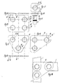
- the coupling elements 10 are provided with a different number of perforations 16 and folds 16 'for receiving hinge axes 9 (Fig.5). It is conceivable to have one in a single perforation 16 of a coupling element according to FIGS. 16, 17 15, which is useful, for example, as a closure member of an unused sleeve body 5.
- the hinge axis 9 dips with a molded collar 22 in the fold 16 '. 18 shows a connecting member 8 formed by a coupling member 10 and articulated axes 9 for connecting three wall elements 1.
- the wall elements can be swiveled out to one another as desired and can also be folded onto one another.
- a plate-shaped coupling element 10 with four perforations 16 is used, which can accommodate two or more e.g. four hinge axes 9 of FIG. 20 is used.
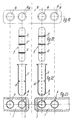
- the wall elements 1 have two bores 4 for receiving sleeve bodies 5 according to FIG. 22.
- the sleeve bodies 5 inserted into bores 4 of the wall elements 1 accommodate cylinder bodies 17, which are frictionally fixed by O-rings 12 in the sleeve bodies 5 and are supported on the sleeve bodies 5 by means of collars 18 via screw threads 19 are threaded bolts 20 can be screwed into the cylinder body 17, which support tilting and rotating support plates 21.
- screwing in the threaded bolts 20 to a greater or lesser extent unevenness in the installation surfaces relative to the wall elements 1 can be compensated for.
Landscapes
- Engineering & Computer Science (AREA)
- Architecture (AREA)
- Physics & Mathematics (AREA)
- Electromagnetism (AREA)
- Civil Engineering (AREA)
- Structural Engineering (AREA)
- Hinges (AREA)
- Dowels (AREA)
- Quick-Acting Or Multi-Walled Pipe Joints (AREA)
- Finishing Walls (AREA)
Abstract
Description
- Die Erfindung betrifft eine Vorrichtung zum lösbar gelenkigen Verbinden von tafelförmigen Wandelementen, insbesondere Mehrschichtplatten mit in der Stirnseite der Wandelemente einsteckbaren Verbindungsgliedern, die mit in festem Abstand achsparallel nebeneinander verbundenen Gelenkachsen in an benachbarten Wandelementen ausgebildeten Lagern schwenkbeweglich eingreifen.
- Bei Wandelementen (DE-GM 85 28 710) ist es zur gelenkigen Verbindung derselben bekannt in den Bereichen der Längsrandkanten der Wandelemente als Schwenklager dienende Formteile über diese vorstehend anzuordnen und vermittels kastenförmigen Anformungen an den Deckschichten der Wandelemente durch Klebung zu halten. Die Schwenklager und die Anformungen sind dabei durch komplizierte Kunststoff-Formteile gebildet, wobei die Schwenklager der Aufnahme der Gelenkachsen von Verbindungsgliedern dienen. Abgesehen davon, daß diese Schwenklager zu arbeitsaufwendigen Wandelementen Anlaß geben, zeigen sie eine geringe Stabilität und eine labile Festlegung an den Deckschichten der Wandelemente Außerdem sind zu Wandelementen mit verschieden großen lichten Abständen der Deckschichten jeweils in der Breite angepaßte Schwenklager und kastenförmige Anfor mungen erforderlich, wodurch auch eine platzaufwendige Lagerhaltung für die Wandelemente notwendig ist.
- Es ist Aufgabe der Erfindung, einfache Maßnahmen zu schaffen, die sicher eine stabile gelenkige Verbindung von Wandelementen ergeben.
- Erfindungsgemäß ist diese Aufgabe gelöst, durch parallel im Abstand der Längsrandkanten in Stirnseiten der Wandelemente eingebrachte Bohrungen angeordnete zylindrische Hülsenkörper und verschieb- und drehbar in den Hülsenkörpern eingreifende, miteinander im Abstand durch Kuppelglieder verbundene Gelenkachsen. Zweckmäßig sind die Hülsenkörper durch Klemmspannung in den Bohrungen der Wandelemente fixiert. Es ist auch möglich, die Hülsenkörper durch Klebung in den Bohrungen der Wandelemente zu fixieren. Die Vorrichtung erlaubt die Hülsenkörper mit beliebig weitem, den Festigkeitseigenschaften der jeweiligen Wandelemente Rechnung tragendem Abstand von den Längsrandkanten in die Wandelemente einzusetzen, wodurch etwaige Querkräfte von den Wandelementen sicher aufgenommen werden um Ausbrechungen, Ausspreizungen oder unbeabsichtigtes Lösen der Vorrichtung zu verhindern. Außerdem läßt sich die Vorrichtung mit gleichen Hülsenkörpern in verschieden dicken Wandelementen aus beliebigen Werkstoffen anordnen. So ist denkbar, die Hülsenkörper gleichermaßen z.B. in Mehrschichtplatten oder in Vollwerkstoff-Platten, wie Spanplatten, Holz- bzw. Kunststoff-Platten auszubilden. Schließlich erfordern die Hülsenkörper auch keine komplizierte Einhaltung von Toleranzen zu irgendwelchen Befestigungschichten mehrschichtiger Wandelemente. Ferner entfallen komplizierte Klebungen, wodurch die Vorrichtung einfach herstellbar und zu handhaben ist.
- In Ausgestaltung der Vorrichtung ist vorgesehen, die Kuppelglieder und die zugeordneten Gelenkachsen durch einen gemeinsamen Formteil zu bilden. Als einfachster Formteil ist ein im wesentlichen u-förmig gebogener Rundstab, z.B. aus Eisenwerkstoff denkbar. Weiter ist vorgesehen, Formteile mit mindestens zwei im Abstand parallel nebeneinander angeordnete Gelenkachsen anzuwenden. Die Anzahl der Gelenkachsen richtet sich dabei nach der jeweiligen Anzahl der gleichzeitig zu verbindenden Wandelemente im Bereich der Knotenpunkte. Bevorzugt können als Kuppelglieder ebene Streifen- oder Plattenteile mit Ausnehmungen für die Aufnahme und Festlegung der Gelenkachsen dienen. Die Ausnehmungen sind zweckmäßig mit einer Falz versehen, in die die Gelenkachsen mit über die Umfangsfläche derselben vorstehenden Ansätzen abstützbar und/oder abstütz- und festlegbar sind. Die Ansätze können durch an den Gelenkachsen angeformte Ringbunde od.dgl. gebildet sein. Eine besonders einfache, nachgiebige Abstützung ist dann erzielbar, wenn die Ansätze durch in Ringnuten der Gelenkachsen geführte O-Ringe gebildet sind. Die O-Ringe bewirken eine reibschlüssige Verbindung und gleichen Toleranzen zwischen Gelenkachsen und Kuppelglieder aus.
- Weiter ist vorgesehen, daß die Gelenkachsen an den in die Hülsenkörper eingreifenden Abschnitten jeweils in Ringnuten geführte O-Ringe aufweisen und daß durch Verformung der O-Ringe die Gelenkachsen in den Hülsenkörpern freigebar, festlegbar sind. Eine Begrenzung der Einstecktiefe der Gelenkachsen läßt sich darüberhinaus noch erzielen, wenn die Hülsenkörper innen mindestens einen teilweise umlaufend ausgebildeten Bund als Widerlager für die Gelenkachsen aufweisen. Es versteht sich, daß auch Bundabschnitte die Abstützung der Gelenkachsen vornehmen können.
- Die Erfindung sieht weiter Maßnahmen zum Ausgleich von Bodenunebenheiten bei aufgestellten Wandelementen dadurch vor, daß die Hülsenkörper auf diese mit einem Bund abstützbare Zylinderkörper fest oder verschieblich fest aufnehmen und daß in den Zylinderkörpern und/oder den Bunden Bolzen über axiale Kurven verstellbar eingreifen und daß die Bolzen an den freien Enden kipp- und drehbar ausgebildete Stützplatten aufweisen. Als axiale Kurven sind in einfacher Weise Schraubgewinde denkbar
- Die Anordnung der Hülsenkörper als wesentliche Vorrichtungsteile gibt die Möglichkeit, die Stirnseiten der Wandelemente durch mit Durchführungsöffnungen für die Hülsenkörper versehene Umleimer wandelementenfest abzudecken. Die dabei neben den Hülsenkörpern verbleibenden Wandelementenabschnitte sind groß genug um ein sicheres Verbinden der Umleimer z.B. durch Klebung möglich zu machen. Es versteht sich, daß die einander zugewandten Längsseiten der Wandelemente in beliebiger Weise ausgeführt sein können. So besteht die Möglichkeit die Wandelemente in diesen Bereichen kantig oder kreisbogenförmig zu begrenzen. Auch ist denkbar anderweitig beliebige Querschnittsformen für die Längsrandflächen der Wandelemente, die auch durch Umleimer gebildet sein können, vorzusehen.
- Die Erfindung ist anhand von Ausführungsbeispielen in der Zeichnung verdeutlicht. Hierin zeigen:
- Fig. 1 Wandelemente mit einer Vorrichtung zum Verbinden, perspektivisch,
- Fig. 2 ein Verbindungsglied perspektivisch,
- Fig. 3 ein Verbindungsglied anderer Ausführung perspektivisch,
- Fig. 4 einen Teilschnitt der Wandelemente der Fig. 1 perspektivisch,
- Fig. 5 Gelenkachsen eines Verbindungsgliedes gemäß einer Ausführungsform in Seitenansicht,
- Fig. 6 Hülsenkörper im Schnitt,
- Fig. 7 Teilschnitte von Wandelementen,
- Fig. 8 Wandelemente mit einer Vorrichtung gemäß den Fig. 5, 6 und 9,
- Fig. 9 ein Kuppelglied für Gelenkachsen in Draufsicht,
- Fig.10 ein Kuppelglied der Fig. 9 in Seitenansicht,
- Fig 11 ein Kuppelglied für die Aufnahme von vier Gelenkachsen in Draufsicht,
- Fig.12 ein Kuppelglied für die Aufnahme von drei Gelenkachsen in Draufsicht,
- Fig.13 ein Kuppelglied gemäß Fig. 12 in Seitenansicht
- Fig.14 ein Kuppelglied anderer Ausbildung für die Aufnahme von drei Gelenkachsen in Draufsicht,
- Fig.15 eine Gelenkachse einer weiteren Ausführung in Seitenansicht,
- Fig.16 ein Kuppelglied für die Aufnahme der Gelenkachsen der Fig. 15 in Seitenansicht,
- Fig.17 ein Kuppelglied nach Fig. 16 in Draufsicht
- Fig.18 Wandelemente mit einem Kuppelglied nach Fig. 14 in Draufsicht,
- Fig.19 ein Kuppelglied für die Aufnahme von vier Gelenkachsen in Draufsicht,
- Fig.20 und 21 Gelenkachsen für ein Kuppelglied der Fig.19 in Seitenansicht,
- Fig.22 Hülsenkörper im Schnitt,
- Fig.23 Teilschnitte von Wandelementen mit je zwei in diesen angeordneten Hülsenkörper,
- Fig.24 Fußstützen in Seitenansicht,
- Fig.25 Hülsenkörper für die Aufnahme der Fußstützen nach Fig. 24 und
- Fig.26 Teilschnitte von Wandelementen.
- In der Fig. 1 sind mit 1 Wandelemente bezeichnet, die z.B. aus Vollwerkstoff gebildet sind. An den einander zugewandten Längsrandkanten 3 tragen durch Klebung befestigt die Wandelemente 1 im Querschnitt halbkreisbogenförmige Umleimer 2. Im Abstand der Längsrandkanten 3 sind in den Stirnseiten 13 der Wandelemente 1 Bohrungen 4 eingebracht, die der Aufnahme von zylindrischen Hülsenkörpern 5 dienen. Die Hülsenkörper 5 sind aus beliebigem Werkstoff, z.B. einem Kunststoff oder metallischem Werkstoff gefertigt. An ihrem Einsteckende sind die Hülsenkörper 5 mit einem Einführungskonus 6 versehen. In die Mittelöffnungen 7 der Hülsenkörper 5 sind Verbindungsglieder 8 einbringbar, die eine schwenkbeweglich gelenkige Verbindung der Wandelemente 1 aneinander ergeben. Die Verbindungsglieder 8 ermöglichen Abschwenkungen der Wandelemente 1 in beliebige Richtungen und versetzten Ebenen. Die Fig. 2 zeigt die einfachste Ausführungsform eines Verbindungsgliedes 8 aus einem u-förmig gebogenen Rundstab, wobei mit 9 Gelenkachsen bezeichnet sind, die durch ein Kuppelglied 10 miteinander fest verbunden sind.
- Beim Verbindungsglied 8 der Fig. 3 sind zwei Gelenkachsen 9 achsparallel im Abstand voneinander fest an einem plattenförmigen Kuppelglied 10 angeordnet. Durch Einschieben der Gelenkachsen 9 in die Mittelöffnungen 7 der Hülsenkörper 5 ist eine Verbindung der beiden Wandelemente 1 erzielbar. Die Gelenkachsen 9 weisen in den in die Hülsenkörper einschiebbaren Abschnitten 9′ Ringnuten 11 für die Aufnahme von O-Ringen 12 auf, die eine reibschlüssige Fixierung der Gelenkachsen 9 in den Hülsenkörpern 5 ergeben. Außerdem gleichen die O-Ringe 12 Fertigungstoleranzen aus. Die Fig.4 läßt erkennen, daß die Stirnseiten 13 der Wandelemente 1 durch streifenförmige Umleimer 14 abgedeckt sein können, die durch die Hülsenkörper 5 im Bereich der Bohrungen 4 durchgriffen sind. Die Umleimer 14 finden hierbei genügend breite Befestigungsflächen neben den Hülsenkörpern 5 um an den Wandelementen 1 dauerhaft zu halten.
- Die Gelenkachsen 9 der Fig. 5 und 8 weisen im Mittelabschnitt je einen weiteren O-Ring 12′ auf, der die Gelenkachsen 9 in den Kuppelgliedern 10 fixiert. Durch Verquetschen der O-Ringe 12′ (Fig. 8) in Lochungen 16 bzw. sich an diesen anschließende Falze 16′ ist eine Verbindung der Gelenkachsen 9 mit dem Kuppelglied 10 und durch das so geschaffene Verbindungsglied eine gelenkige Verbindung der Wandelemente 1 miteinander geschaffen. Die Hülsenkörper 5 sind an den inneren Umfangsflächen mit einem umlaufenden Bund 15 versehen, an dem sich die Gelenkachsen 9 bei Erreichen der Arbeitsstellungen mit der Stirnseite abstützen.
- Während beim Ausführungsbeispiel der Fig. 1 die Wandelemente 1 in etwas größerem Abstand miteinander verbunden sind, sind die Wandelemente 1 der Fig. 7 mit ihren Längsrandkanten 3 annähernd aneinander angestellt und durch entsprechende Abstände von Bohrungen 4 und Gelenkachsen 9 verbunden. Es versteht sich, daß die Abstände der zu verbindenen Wandelemente 1 beliebig gewählt sein können.
- Die Fig. 10, 11, 12, 13 und 14 zeigen verschiedene Ausführungen von Kuppelgliedern 10. Die Kuppelglieder 10 sind mit einer unterschiedlichen Anzahl Lochungen 16 und Falze 16′ für die Aufnahme von Gelenkachsen 9 (Fig.5) versehen. Es ist denkbar, in eine einzige Lochung 16 eines Kuppelgliedes gemäß Fig. 16, 17 eine Gelenkachse 9 der Ausführung der Fig. 15 einzusetzen, die z.B. als Verschlußglied eines ungenutzten Hülsenkörpers 5 dienlich ist. Die Gelenkachse 9 taucht mit einem angeformten Bund 22 in die Falz 16′ ein. Die Fig. 18 zeigt ein durch ein Kuppelglied 10 und Gelenkachsen 9 gebildetes Verbindungsglied 8 zur Verbindung von drei Wandelementen 1. Die Wandelemente sind beliebig zueinander abschwenkbar und auch aufeinander klappklappbar.
- Abweichend findet beim Ausführungsbeispiel der Fig. 19 und 23 ein plattenförmiges Kuppelglied 10 mit vier Lochungen 16 Anwendung, das der wahlweisen Aufnahme von zwei oder mehr z.B. vier Gelenkachsen 9 der Fig. 20 dient. Die Wandelemente 1 weisen zwei Bohrungen 4 für die Aufnahme von Hülsenkörpern 5 gemäß Fig. 22 auf. Mittels der Vorrichtung der Fig. 19 bis 23 besteht die Möglichkeit wahlweise bei Verwendung von vier Gelenkachsen 9 die Wandelemente 1 in gleicher Ebene starr zu verbinden. Bei Anwendung von nur einer Gelenkachse 9 in jedem der beiden Wandelemente, verbleiben diese abschwenkbar.
- Bei der Vorrichtung der Fig. 24 bis 26 nehmen die in Bohrungen 4 der Wandelemente 1 eingesetzten Hülsenkörper 5 Zylinderkörper 17 auf, die durch O-Ringe 12 in den Hülsenkörpern 5 reibungsschlüssig fixiert sind und sich auf die Hülsenkörper 5 mittels Bunden 18 abstützen Über Schraubgewinde 19 sind Gewindebolzen 20 in die Zylinderkörper 17 eindrehbar, die kipp- und drehbar ausgebildete Stützplatten 21 tragen. Durch mehr oder weniger weites Eindrehen der Gewindebolzen 20 sind Unebenheiten von Aufstellflächen zu den Wandelementen 1 ausgleichbar.
Claims (15)
Priority Applications (4)
| Application Number | Priority Date | Filing Date | Title |
|---|---|---|---|
| EP88118736A EP0367857B1 (de) | 1988-11-10 | 1988-11-10 | Vorrichtung zum lösbar gelenkigen Verbinden von tafelförmigen Wandelmenten |
| DE8888118736T DE3865205D1 (de) | 1988-11-10 | 1988-11-10 | Vorrichtung zum loesbar gelenkigen verbinden von tafelfoermigen wandelmenten. |
| ES198888118736T ES2026243T3 (es) | 1988-11-10 | 1988-11-10 | Dispositivo para la union articulada desmontable de elementos tubulares de pared. |
| AT88118736T ATE67809T1 (de) | 1988-11-10 | 1988-11-10 | Vorrichtung zum loesbar gelenkigen verbinden von tafelfoermigen wandelmenten. |
Applications Claiming Priority (1)
| Application Number | Priority Date | Filing Date | Title |
|---|---|---|---|
| EP88118736A EP0367857B1 (de) | 1988-11-10 | 1988-11-10 | Vorrichtung zum lösbar gelenkigen Verbinden von tafelförmigen Wandelmenten |
Publications (2)
| Publication Number | Publication Date |
|---|---|
| EP0367857A1 true EP0367857A1 (de) | 1990-05-16 |
| EP0367857B1 EP0367857B1 (de) | 1991-09-25 |
Family
ID=8199548
Family Applications (1)
| Application Number | Title | Priority Date | Filing Date |
|---|---|---|---|
| EP88118736A Expired - Lifetime EP0367857B1 (de) | 1988-11-10 | 1988-11-10 | Vorrichtung zum lösbar gelenkigen Verbinden von tafelförmigen Wandelmenten |
Country Status (4)
| Country | Link |
|---|---|
| EP (1) | EP0367857B1 (de) |
| AT (1) | ATE67809T1 (de) |
| DE (1) | DE3865205D1 (de) |
| ES (1) | ES2026243T3 (de) |
Cited By (6)
| Publication number | Priority date | Publication date | Assignee | Title |
|---|---|---|---|---|
| EP0505649A1 (de) * | 1991-03-25 | 1992-09-30 | Steelcase Strafor (S.A.) | Trennwandsystem mit variabler Anordnung |
| WO1992021832A1 (de) * | 1991-06-03 | 1992-12-10 | Rainer Baars | Vorrichtung zum lösbar gelenkigen verbinden von tafelförmigen wandelementen |
| EP0535566A1 (de) * | 1991-10-01 | 1993-04-07 | Martin Wiese | Wand aus mehreren lösbar miteinander verbundenen Platten |
| US5694997A (en) * | 1993-05-05 | 1997-12-09 | Styger; John Errol | Gravity exhibition stand |
| WO2001059225A1 (en) * | 2000-02-09 | 2001-08-16 | Vetenskapsstaden | A connection device |
| WO2019229244A1 (de) * | 2018-06-01 | 2019-12-05 | Frank Maager | System zum aufbau eines möbels |
Citations (3)
| Publication number | Priority date | Publication date | Assignee | Title |
|---|---|---|---|---|
| DE2100164A1 (en) * | 1971-01-04 | 1972-07-27 | Ed. Scharwächter KG, 5630 Remscheid | Motor vehicle door hinge - preventing creeping in hinge pin locating bushings by interposition of washers |
| DE8528710U1 (de) * | 1985-10-09 | 1986-01-30 | Fugmann, Stephan | Wand, die aus mehreren lösbar miteinander gekuppelten Wandelementen besteht |
| DE8619759U1 (de) * | 1986-07-23 | 1987-01-29 | Preform Raumgliederungssysteme GmbH, 91555 Feuchtwangen | Stellwand aus mehreren Wandelementen |
-
1988
- 1988-11-10 ES ES198888118736T patent/ES2026243T3/es not_active Expired - Lifetime
- 1988-11-10 DE DE8888118736T patent/DE3865205D1/de not_active Expired - Lifetime
- 1988-11-10 EP EP88118736A patent/EP0367857B1/de not_active Expired - Lifetime
- 1988-11-10 AT AT88118736T patent/ATE67809T1/de not_active IP Right Cessation
Patent Citations (3)
| Publication number | Priority date | Publication date | Assignee | Title |
|---|---|---|---|---|
| DE2100164A1 (en) * | 1971-01-04 | 1972-07-27 | Ed. Scharwächter KG, 5630 Remscheid | Motor vehicle door hinge - preventing creeping in hinge pin locating bushings by interposition of washers |
| DE8528710U1 (de) * | 1985-10-09 | 1986-01-30 | Fugmann, Stephan | Wand, die aus mehreren lösbar miteinander gekuppelten Wandelementen besteht |
| DE8619759U1 (de) * | 1986-07-23 | 1987-01-29 | Preform Raumgliederungssysteme GmbH, 91555 Feuchtwangen | Stellwand aus mehreren Wandelementen |
Cited By (7)
| Publication number | Priority date | Publication date | Assignee | Title |
|---|---|---|---|---|
| EP0505649A1 (de) * | 1991-03-25 | 1992-09-30 | Steelcase Strafor (S.A.) | Trennwandsystem mit variabler Anordnung |
| WO1992021832A1 (de) * | 1991-06-03 | 1992-12-10 | Rainer Baars | Vorrichtung zum lösbar gelenkigen verbinden von tafelförmigen wandelementen |
| EP0535566A1 (de) * | 1991-10-01 | 1993-04-07 | Martin Wiese | Wand aus mehreren lösbar miteinander verbundenen Platten |
| US5694997A (en) * | 1993-05-05 | 1997-12-09 | Styger; John Errol | Gravity exhibition stand |
| WO2001059225A1 (en) * | 2000-02-09 | 2001-08-16 | Vetenskapsstaden | A connection device |
| WO2019229244A1 (de) * | 2018-06-01 | 2019-12-05 | Frank Maager | System zum aufbau eines möbels |
| US11974673B2 (en) | 2018-06-01 | 2024-05-07 | Frank Maager | Method for constructing a piece of furniture |
Also Published As
| Publication number | Publication date |
|---|---|
| EP0367857B1 (de) | 1991-09-25 |
| ES2026243T3 (es) | 1992-04-16 |
| DE3865205D1 (de) | 1991-10-31 |
| ATE67809T1 (de) | 1991-10-15 |
Similar Documents
| Publication | Publication Date | Title |
|---|---|---|
| DE3049957C2 (de) | Geraetegestell | |
| DE29517113U1 (de) | Tisch | |
| DE69201684T2 (de) | Vorrichtung zur Amplitudenbegrenzung der Schwenkbarkeit zweier gelenkig gelagerter Elemente. | |
| DE2821132C2 (de) | Aufspannvorrichtung für eine Handbohrmaschine | |
| DE3517304C2 (de) | ||
| EP0367857B1 (de) | Vorrichtung zum lösbar gelenkigen Verbinden von tafelförmigen Wandelmenten | |
| DE8814091U1 (de) | Vorrichtung zum lösbar gelenkigen Verbinden von tafelförmigen Wandelementen | |
| DE2854083C2 (de) | Falttür, insbesondere für Duschkabinen | |
| DE3108437C2 (de) | Vorrichtung zum Montieren von Einbaudosen für Elektroinstallation | |
| EP0034640B1 (de) | Schraubenantrieb | |
| DE4306802C1 (de) | Deckenstativ | |
| DE3538003C2 (de) | Variabler Tisch | |
| EP0445363A1 (de) | Fräs- oder Bohrvorrichtung | |
| DE8815500U1 (de) | Vorrichtung zum lösbar gelenkigen Verbinden von tafelförmigen Wandelementen | |
| DE3842024A1 (de) | Vorrichtung zum loesbar gelenkigen verbinden von tafelfoermigen wandelementen | |
| DE2808787C2 (de) | Stativ mit Verstrebungen der Stativbeine | |
| DE9106811U1 (de) | Vorrichtung zum lösbar gelenkigen Verbinden von tafelförmigen Wandelementen | |
| DE2751281A1 (de) | Steuervorrichtung fuer schneidbrenner | |
| DE20014981U1 (de) | Gerät zum Anzeichnen von Ausschnitten und/oder Winkeln beim Verlegen platten- oder tafelförmiger Bauelemente | |
| WO1992021832A1 (de) | Vorrichtung zum lösbar gelenkigen verbinden von tafelförmigen wandelementen | |
| DE3325552A1 (de) | Handwerkermesser | |
| DE8022550U1 (de) | Leuchte | |
| DE3908979A1 (de) | Vorrichtung zum loesbaren verbinden von tafelfoermigen wandelementen | |
| DE1750716C (de) | Vorrichtung zum Aufhängen von Gegenständen, insbesondere Rohren und dgl., mit begrenzter Bewegungsfreiheit. Ausscheidung aus: 1303082 | |
| DE1963344C (de) | Gerat zum Anreißen von Treppenstufen in Bauten |
Legal Events
| Date | Code | Title | Description |
|---|---|---|---|
| PUAI | Public reference made under article 153(3) epc to a published international application that has entered the european phase |
Free format text: ORIGINAL CODE: 0009012 |
|
| AK | Designated contracting states |
Kind code of ref document: A1 Designated state(s): AT BE CH DE ES FR GB GR IT LI LU NL SE |
|
| RBV | Designated contracting states (corrected) |
Designated state(s): AT BE CH DE ES FR GB IT LI NL SE |
|
| 17P | Request for examination filed |
Effective date: 19901115 |
|
| 17Q | First examination report despatched |
Effective date: 19910313 |
|
| GRAA | (expected) grant |
Free format text: ORIGINAL CODE: 0009210 |
|
| AK | Designated contracting states |
Kind code of ref document: B1 Designated state(s): AT BE CH DE ES FR GB IT LI NL SE |
|
| REF | Corresponds to: |
Ref document number: 67809 Country of ref document: AT Date of ref document: 19911015 Kind code of ref document: T |
|
| REF | Corresponds to: |
Ref document number: 3865205 Country of ref document: DE Date of ref document: 19911031 |
|
| ITF | It: translation for a ep patent filed | ||
| ET | Fr: translation filed | ||
| GBT | Gb: translation of ep patent filed (gb section 77(6)(a)/1977) | ||
| REG | Reference to a national code |
Ref country code: ES Ref legal event code: FG2A Ref document number: 2026243 Country of ref document: ES Kind code of ref document: T3 |
|
| PLBE | No opposition filed within time limit |
Free format text: ORIGINAL CODE: 0009261 |
|
| STAA | Information on the status of an ep patent application or granted ep patent |
Free format text: STATUS: NO OPPOSITION FILED WITHIN TIME LIMIT |
|
| 26N | No opposition filed | ||
| PGFP | Annual fee paid to national office [announced via postgrant information from national office to epo] |
Ref country code: SE Payment date: 19921026 Year of fee payment: 5 |
|
| PGFP | Annual fee paid to national office [announced via postgrant information from national office to epo] |
Ref country code: BE Payment date: 19921116 Year of fee payment: 5 |
|
| PGFP | Annual fee paid to national office [announced via postgrant information from national office to epo] |
Ref country code: FR Payment date: 19921125 Year of fee payment: 5 |
|
| PGFP | Annual fee paid to national office [announced via postgrant information from national office to epo] |
Ref country code: CH Payment date: 19921229 Year of fee payment: 5 |
|
| PGFP | Annual fee paid to national office [announced via postgrant information from national office to epo] |
Ref country code: DE Payment date: 19930126 Year of fee payment: 5 |
|
| PGFP | Annual fee paid to national office [announced via postgrant information from national office to epo] |
Ref country code: GB Payment date: 19930910 Year of fee payment: 6 |
|
| PGFP | Annual fee paid to national office [announced via postgrant information from national office to epo] |
Ref country code: ES Payment date: 19931006 Year of fee payment: 6 |
|
| PG25 | Lapsed in a contracting state [announced via postgrant information from national office to epo] |
Ref country code: SE Effective date: 19931111 |
|
| PG25 | Lapsed in a contracting state [announced via postgrant information from national office to epo] |
Ref country code: LI Effective date: 19931130 Ref country code: CH Effective date: 19931130 Ref country code: BE Effective date: 19931130 |
|
| PGFP | Annual fee paid to national office [announced via postgrant information from national office to epo] |
Ref country code: NL Payment date: 19931130 Year of fee payment: 6 Ref country code: AT Payment date: 19931130 Year of fee payment: 6 |
|
| BERE | Be: lapsed |
Owner name: STOLZEL CHRISTOPH Effective date: 19931130 Owner name: BAARS RAINER Effective date: 19931130 |
|
| PG25 | Lapsed in a contracting state [announced via postgrant information from national office to epo] |
Ref country code: FR Effective date: 19940729 |
|
| REG | Reference to a national code |
Ref country code: CH Ref legal event code: PL |
|
| PG25 | Lapsed in a contracting state [announced via postgrant information from national office to epo] |
Ref country code: DE Effective date: 19940802 |
|
| REG | Reference to a national code |
Ref country code: FR Ref legal event code: ST |
|
| PG25 | Lapsed in a contracting state [announced via postgrant information from national office to epo] |
Ref country code: GB Effective date: 19941110 Ref country code: AT Effective date: 19941110 |
|
| PG25 | Lapsed in a contracting state [announced via postgrant information from national office to epo] |
Ref country code: ES Free format text: LAPSE BECAUSE OF NON-PAYMENT OF DUE FEES Effective date: 19941111 |
|
| EUG | Se: european patent has lapsed |
Ref document number: 88118736.3 Effective date: 19940610 |
|
| PG25 | Lapsed in a contracting state [announced via postgrant information from national office to epo] |
Ref country code: NL Effective date: 19950601 |
|
| GBPC | Gb: european patent ceased through non-payment of renewal fee |
Effective date: 19941110 |
|
| NLV4 | Nl: lapsed or anulled due to non-payment of the annual fee | ||
| REG | Reference to a national code |
Ref country code: ES Ref legal event code: FD2A Effective date: 19951214 |
|
| PG25 | Lapsed in a contracting state [announced via postgrant information from national office to epo] |
Ref country code: IT Free format text: LAPSE BECAUSE OF NON-PAYMENT OF DUE FEES Effective date: 20051110 |