EP0369689B1 - Vorrichtung zur Vektorquantisierung von Bildern - Google Patents
Vorrichtung zur Vektorquantisierung von Bildern Download PDFInfo
- Publication number
- EP0369689B1 EP0369689B1 EP89311643A EP89311643A EP0369689B1 EP 0369689 B1 EP0369689 B1 EP 0369689B1 EP 89311643 A EP89311643 A EP 89311643A EP 89311643 A EP89311643 A EP 89311643A EP 0369689 B1 EP0369689 B1 EP 0369689B1
- Authority
- EP
- European Patent Office
- Prior art keywords
- block
- codebook
- row
- codeword
- column
- Prior art date
- Legal status (The legal status is an assumption and is not a legal conclusion. Google has not performed a legal analysis and makes no representation as to the accuracy of the status listed.)
- Expired - Lifetime
Links
Images


Classifications
-
- H—ELECTRICITY
- H04—ELECTRIC COMMUNICATION TECHNIQUE
- H04N—PICTORIAL COMMUNICATION, e.g. TELEVISION
- H04N19/00—Methods or arrangements for coding, decoding, compressing or decompressing digital video signals
- H04N19/50—Methods or arrangements for coding, decoding, compressing or decompressing digital video signals using predictive coding
- H04N19/503—Methods or arrangements for coding, decoding, compressing or decompressing digital video signals using predictive coding involving temporal prediction
- H04N19/51—Motion estimation or motion compensation
- H04N19/527—Global motion vector estimation
-
- G—PHYSICS
- G06—COMPUTING OR CALCULATING; COUNTING
- G06T—IMAGE DATA PROCESSING OR GENERATION, IN GENERAL
- G06T9/00—Image coding
- G06T9/008—Vector quantisation
-
- H—ELECTRICITY
- H04—ELECTRIC COMMUNICATION TECHNIQUE
- H04N—PICTORIAL COMMUNICATION, e.g. TELEVISION
- H04N19/00—Methods or arrangements for coding, decoding, compressing or decompressing digital video signals
- H04N19/85—Methods or arrangements for coding, decoding, compressing or decompressing digital video signals using pre-processing or post-processing specially adapted for video compression
- H04N19/86—Methods or arrangements for coding, decoding, compressing or decompressing digital video signals using pre-processing or post-processing specially adapted for video compression involving reduction of coding artifacts, e.g. of blockiness
-
- H—ELECTRICITY
- H04—ELECTRIC COMMUNICATION TECHNIQUE
- H04N—PICTORIAL COMMUNICATION, e.g. TELEVISION
- H04N19/00—Methods or arrangements for coding, decoding, compressing or decompressing digital video signals
- H04N19/90—Methods or arrangements for coding, decoding, compressing or decompressing digital video signals using coding techniques not provided for in groups H04N19/10-H04N19/85, e.g. fractals
- H04N19/94—Vector quantisation
Definitions
- Data processing for image transmission has used a variety of techniques in the past for reducing the bit rate required for transmission of the data.
- a number of these techniques have been broadly characterized as image compression, which means that perceptually irrelevant aspects of the image data are removed and the redundancies in the data are reduced by the coding technique in order to reduce the bit rate required.
- image compression means that perceptually irrelevant aspects of the image data are removed and the redundancies in the data are reduced by the coding technique in order to reduce the bit rate required.
- the variety of techniques has multiplied as the requirements for image quality have increased at the same time that the demand for the available channel bandwidth has increased.
- One of the techniques for achieving such results is the technique known as image compression using vector quantization, in which blocks or vectors, each representing a group of individual pixels, are independently encoded. This technique has been demonstrated to be effective for achieving moderately low rates in bits per pixel.
- the encoder and decoder of such a system have a feedback structure in which the internal states determined by the outputs are fed back and used together with the inputs for encoding and decoding.
- the goal of such finite state techniques is to maintain the quality of the transmission obtained while achieving the desired low bit rate. If the internal state can accurately represent a small region that contains the input vector to be encoded, finite state vector quantization can achieve the aforesaid goal by using a relatively small time varying set of codebooks.
- each pixel block usually a rectangular pixel block, has more adjacent pixels outside the block than does a one-dimensional sample block as in the voice coding environment, and the other is the fact that most common images have very high adjacent pixel correlation.
- Aravind and Gersho also disclose, in ICASSP 86 Proceedings, April 7-11 1986, pages 137-140, 'Low-rate image coding with finite-state vector quantization', an image coding technique as set out in the preamble of claim 1.
- the blocks in the same column and preceding row and in the same row and preceding column are classified by means of an edge classifier, which classifies the block according to any edge (i.e. a transition between black and white) which is found or, if no such edge is found, by means of the mean intensity of the block.
- This edge classification and mean intensity classification is carried out by using all pixels in the relevant blocks.
- a newly blooming market for economical storage techniques for images for archival, for example, for medical, geophysical, aerial or satellite photography purposes, for electronic shopping or for video teleconferencing increases the need to push such techniques to the limit and furthermore, to make simplicity of the decoding a primary objective of the system even at the expense of some complication of the encoding techniques.
- the invention is as set out in the indepedent claims 1, 4, 7 and 8. It has been discovered that the most effective way of incorporating memory into such a system is to employ the 2-dimensional spatial contiguity in a way that directly controls intensity continuity between spatially close pixels of the adjacent blocks. There is stripped away any consideration of indirect information, such as classification of discontinuities. so that the invention uses state codebooks chosen for best intensity matching to the relatively nearest pixels of the vectors representing the prior block and the one-row-prior block, in order not to lose the significance of their spatial contiguity.
- variable length coding based on training image statistics or on input image itself further increases the effectiveness of my modified system. Since the variable length noiseless coding which I propose to use is simple, its full description can be transmitted to the receiver in a communication system with an insignificant increase in bit rate. In fact, according to this feature of the invention, a family of variable length noiseless codes are described that closely achieve so-called channel symbol entropies. This particular feature of the invention can also be retrofitted to other finite state vector quantization designs.
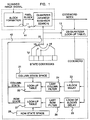
- FIG. 1 there is shown a basic embodiment which is organized similarly to systems that can be used to practice encoding algorithms of the finite state vector quantization type, including that disclosed in the above cited article by Aravind et al; but the embodiment of FIG. 1, upon a closer perusal, will be seen to be specifically adapted to the particular features of my invention. More specifically, in FIG. 1 is shown an embodiment of my invention used in a transmitter of a communication system transmitting images between remote locations. The organization of this transmitter is adapted to admit the scanned image signal, scanned in the conventional way for television image transmission but optionally with higher resolution. It also includes a way of forming the image pixels into blocks as shown by the block formation stage 11 of FIG. 1.
- Each block is a 4x4 block of pixels, for example, the first block includes the first four pixels of each of the first four rows of scanned image pixels.
- Each resulting pixel block then passes to quantizer 12 which performs a nearest neighbor search for selecting the desired entry from among the particular codebook selected as described hereinafter.
- the search is guided by the logic circuit 42 communicating with the encoding section 41, including block 11 and quantizer 12.
- the logic is such as to enable the appropriate codeword index to be transmitted with the appropriately low bit rate but with optimum matching of the pixel block edges as will be more fully described hereinafter.
- the block formation and the quantizer nearest neighbor search are performed as described in Section 2.1.1 of the Aravind article.
- the block of pixels is, for example, a four-by-four block of the smallest image units. These blocks are assembled in the most compact way as one might expect so that they are 4 pixels wide and 4 pixels deep in the direction in which the image is developed across the display or other 2-dimensional representation of the image row by row. In other words, four rows are employed to generate the blocks of adjacent pixels.
- the pixel blocks are then sent to the quantizer. From the currently dynamically selected state codebook through the selected one of the set 14 of switch positions, for example, from switch 20 the limited codebook entries C 1 , C 2 , C n are compared on a minimum distance basis with the actual imput pixel block x for each pixel in the block.
- C i The value of C i is selected which yields the smallest mean squared error; and the index of that codebook value, that is, the value of i is passed from quantizer 12 as the transmitted codeword index. At the same time this codeword index is used as part of the history of the image information which is used to dynamically select the next state codebook which will be used to encode the next block of pixels.
- the logic for employing this image history to select the next state codeword is found in logic circuit 42 of FIG. 1.
- the previous codeword index is passed to dequantizer 13, which is basically a lookup table that converts the previous state codebook index back to a codeword representative of a block; and the resulting output is subjected to delays and other logic processing to affect the subsequent positioning of circuit switch 20.
- the signals are passed through the respective one block delay 23 and one row of blocks delay 25 in order to arrive at the column state output and row state output, respectively, at the appropriate times.
- the lookup tables 22 and 27 involve the column states space 21 and row states space 28, respectively, optionally, to reduce the number of state codebooks 19.
- the column states space 21 and row state space 28 are the sets of representatives for last pixel columns and last pixel rows, respectively, of all the representative blocks in all of the state codebooks 19.
- blocks 21, 22, 27, and 28 are the mechanism for reducing the number of state codebooks which in turn reduces the required memory space (in the encoder). If there is no restriction on the number of state codebooks or upon memory space, these blocks can be eliminated. From among those values of columns and rows of pixels being considered, filters 24 and 26 selectively pass only the last column and the last pixel row, respectively, which are the pixel column and pixel row immediately adjacent to, or overlapped by, the current block being encoded. These are the most relevant pixels to the encoding of the current pixels if discontinuities of values in the image are to be avoided. It is thus in this area of logic circuit 42 that I achieve the distinction in organization and operation from that of the above cited reference of Aravind and Gersho.
- the difference lies in the techniques for selecting one of the state codebooks 19 based on the particular column state arriving at the column state output and the particular row state arriving at the row state output. These values are then applied to control position of switch 20 to control the state codebook which is used in quantizer 12 for the nearest neighbor research in encoding the current block of pixels to be encoded.
- the state codebooks could be ordered so sequential sets of rows states known to be used for like indices of column states are sequentially arrayed by row state index, followed by the like sequential array of row states for the next sequential index of column states, and so on, until all column states known to be used are sequentially arrayed.
- the column state index output from block 22 causes the appropriate counting of column state positions by switch 20, after which the row state index output from block 27 causes the appropriate counting of row state positions of switch 21, within the appropriate array of rows of the previously counted column state.
- the look-up tables 22 and 27 are needed because, for the reduced set 19 of state codebooks not every row state index of the super codebook (described hereinafter) is used with every column state index of the super codebook.
- the selected state codebook will be the one which according to the process of codebook design from statistically similar blocks in the super codebook will be likely to produce the same statistical 2-dimensional properties, that is the most similar adjacent edge, which is a column edge if it was the preceding block or an adjacent row edge if it were the one-row-prior block.
- the nearest neighbor search operations in blocks 22 and 27, can be implemented by look-up tables, if desired.
- logic circuit 42 all the processes employed in logic circuit 42 are lookup table processes and can be in general accomplished very quickly as compared to the computation intensive nearest neighbor search that occurs in quantizer 12.
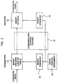
- FIG. 2 is illustrated a further handling of the codeword index output of FIG. 1 to prepare it for actual transmission over transmission medium and for reception at the receiver.
- the codeword index is not necessarily in an optimum binary form for transmission given the characteristics of the medium or the statistical characteristics of the image itself.
- the codeword index is subjected to further binary encoding in encoder 31 which will incidentally involve further reduction of bit rate in response to a prefix length determination in prefix length determiner 33 and the transmission binary codebook 32.
- variable length noiseless codes are advantageous for the system of FIGS. 1 and 3.
- the one-to-one mapping according to FIG. 2 that converts channel symbols into binary sequences is called the binary encoder , and its inverse is called the binary decoder .
- the channel symbols cormng out of a source encoder, such as FSVQ have a finite alphabet (i.e., an alphabet of finite size). Given a class of sources, images in this case, the channel symbols assume a certain probability distribution. Since there are well established theories of noiseless codes for the symbols from a finite alphabet with a known probability distribution, one can simply apply optimal noiseless codes to channel symbols. When the alphabet size is fairly large, however, blind application of noiseless codes such as the Huffman code has potential problems.
- the binary encoder or decoder can be quite complicated or may require very large buffers. These problems are mainly caused by the wide variation of binary codeword length.
- the length of a codeword in a noiseless code is sometimes referred to as a level of the noiseless code.
- the optimal noiseless code designed for one probability distribution can be very poor for another distribution.
- the description of optimal noiseless code needs to be also transmitted to the binary decoder for correct decoding. Unfortunately, such description may contain more than a negligible amount of information. That is, the transmission of the optimal noiseless code description may considerably increase the overall bit rate.
- variable length coding logic 36 of FIG. 2 can be implemented according to the mathematics described below. Alternatively, it can be implemented according to other variable-length noiseless encoding schemes found in the art. The above described version is a preferred alternative but not an exclusive alternative for purposes of the present invention.
- FIG. 3 the receiver which couples to the output of binary decoder 34 and provides the output image of high quality relative to the number of bits transmitted over the communication channel 37.
- That receiver includes dequantizer 43 which is again a lookup table operation identical to that of dequantizer 13 in the transmitter and itself and a logic circuit 44 which is essentially identical to logic circuit 42 of the transmitter.
- the image formation circuit 45 basically reverses the process that forms blocks of pixels in block formation circuit 11 of FIG. 1, subject to some additional operations for overlap matching and decoding, which will be described hereinafter.
- the operation of the transmitter of FIG. 1 can be more definitively mathematically characterized as follows:
- the finite state vector quantizer is basically that of finite state machines, as is defined in the area of digital circuits. Given a vector dimension k, at each sampling time instant i, the encoder maps a k-dimensional source vector x i into a channel symbol y i from a finite alphabet for transmission, and any corresponding receiving decoder maps the channel symbol back into a k-dimensional reproduction vector x ⁇ i .
- the channel symbols are commonly represented by binary sequences.
- Each state codebook is a set of N k-dimensional vectors called codewords.
- the set of state codebooks are indexed by the states, and hence, the total number of state codebooks is equal to the state space size which is M.
- the index set Y ⁇ 1,2, ⁇ , N ⁇ , that all the state codebooks have in common, is called channel symbol space .
- the quantizer is a mapping from the Cartesian product of k-dimensional Euclidean space R k and the state space S to the channel symbol space Y. That is, q: R k ⁇ S ⁇ Y, where ⁇ denotes the Cartesian product.
- the quantizer can also understand the quantizer to be a collection of mappings ⁇ q s :s ⁇ S ⁇ , such that each q s is a mapping from R k to Y. For the convenience of description, however, we will use the former definition of the quantizer.
- the quantizer achieves data compression implies that the quantizer should obviously be a many to one mapping, and thus, its inverse does not exist.
- a mapping p called de-quantizer, to mimic the inverse of the quantizer.
- the de-quantizer is a mapping from Y ⁇ S to C. If one considers the quantizer to be a collection of mappings ⁇ q s :s ⁇ S ⁇ , the de-quantizer can also be viewed as a collection of one-to-one mappings ⁇ p s :s ⁇ S ⁇ , such that p s :Y ⁇ C s .
- each p s is a table-lookup function that maps each channel symbol into the codeword in C s whose index is the same as the channel symbol. Since the finite state vector quantizer encoder and decoder function as finite state machines, their internal states should be updated at every sampling instant. The update of internal states is done by the next state function f.
- the finite state vector quantizer encoder can be characterized by the quintuple: a state space, a set of state codebooks, a quantizer, a de-quantizer, and a next state function, i.e., (S, ⁇ C s , s ⁇ S ⁇ , q, p, f).
- a state space a set of state codebooks
- a quantizer a de-quantizer
- a next state function i.e., (S, ⁇ C s , s ⁇ S ⁇ , q, p, f).
- the quantizer maps a k-dimensional source vector x i into a channel symbol y i such that y i is the index of the codeword within the state codebook C s i which best approximates x i with respect to a certain criterion.
- the resulting codeword which is the reproduction vector, is denoted by x ⁇ i .
- a simple and ubiquitous criterion is the minimization of the mean squared error, which is defined as where [ x i ] j and [ x ⁇ i ] j are the j-th components of vectors x i and x ⁇ i , respectively.
- the quantizer in our discussion is a memoryless vector quantizer with the state codebook as its codebook.
- the encoder After a channel symbol is produced by the quantizer, the encoder needs to update the state to prepare for the encoding of the next source vector.
- the next state function performs this update by mapping the finite past reproduction vectors into the next state s i+1 . Note that the reproduction vectors are not available yet, though they are implicitly determined during the quantization process.
- the de-quantizer 13 makes reproduction vectors available to the next state function.
- the de-quantizer is a table-lookup function where the lookup table is a state codebook. Given a sampling instant i and a state s i , the de-quantizer maps a channel symbol y i into a codeword in c s i whose index is y i .
- x ⁇ i denotes the reproduction vector at time i
- the finite state vector quantizer decoder is characterized by the quadruple: a state space, a set of state codebooks, a de-quantizer, and a next state function, i.e., (S, ⁇ C s : s ⁇ S ⁇ , p, f). All these components are identical to those of the finite state vector quantizer encoder and are already described in detail.
- the de-quantizer selects the codeword in the state codebook corresponding to the internal state such that the index of the codeword is identical to the received channel symbol. Based on the selected codewords (or reproduction vectors), the next state function updates the internal state of the decoder.
- the next state function of the decoder can keep track of the encoder states. Therefore, the reproduction vectors produced by the decoder is identical to the corresponding reproduction vectors determined in the encoder.
- the finite state vector quantizer encoding is the progressive repetition of the following operations.
- the finite state vector quantizer decoder operation is summarized as the progressive repetition of the following operations.
- a side-match vector quantizer according to my invention is within a class of FSVQ.
- side-match the side-match vector quantizer tries to make the intensity (grey level) transition across the boundaries of the reproduction vectors as smooth as possible.
- the assumption behind side-match vector quantizers is that the pixel rows and columns of the source image are first order Markov processes. If the assumption is true, then the pixels contiguous to the current block (the block to be encoded) carry all the information about the current block which is contained in all the past history. In other words, if the pixel rows and columns are first order Markov, given the pixels that are contiguous to the current block, the current block is conditionally independent of all the rest of the past history.
- the state has to be generated solely by the pixels contiguous to the pixel block to be encoded.
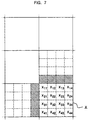
- This fact is closely related to the concept of spatial contiguity stated in Section 1 (see the striped areas in Figure 7).
- the assumption also suggests that the best selection of the state codebook is the set of codewords whose boundary pixels are most similar to the reproduction pixels that contributes to the state generation.
- the state codebook should be the set of codewords with the best "side-match".
- the advantage of "side-match" over other types of finite state vector quantizer is that, even if the reproduction vector is not the best codeword in the super-codebook, the error it introduces is often less visible in the reproduced image.
- the significance of these column and row state vectors is that they represent the reproduction pixels that are contiguous to the source block to be encoded.
- a side-match vector quantizer must have a state codebook for each state in the state space.
- side-match distortion e we first let [ x ] c l and [ x ] r l denote the 1-th column and 1-th row vectors of a block x , respectively.
- the state codebook C s is a subset of the super-codebook that contains N codewords with the smallest side-match distortion, arranged in increasing order of side-match distortion. Note in this definition that the state codebook is not only a set but an ordered set (a sequence). This ordering information is of great importance when we consider noiseless coding hereinafter.
- the quantizer and the de-quantizer of side-match vector quantizer are not different from the definition in general of a finite state vector quantizer or de-quantizer, as the case may be.
- the next state function maps the west reproduction block x ⁇ i into the column state vector u i+1 , and the north reproduction block x ⁇ i-J+1 into the row state vector v i+1 .
- the 256 best matching blocks For each candidate pair of such 10 6 pairs, the 256 best matching blocks, the top row thereof being matched to the row portion of the candidate pair and the left-hand column of each block being to the column portion of the candidate pair, form a tentative state codebook.
- the best matching blocks for each candidate pair can be determined by any of the well-known optimization techniques for vectors, illustratively minimum side-match distortion.
- the state codebooks are represented in a memory or store which comprises the set 19 of state codebooks in FIG. 1.
- column and row state blocks have alphabets u and v , called the column state space and row state space , respectively.
- the state space S of OMVQ is the Cartesian product u ⁇ v.
- the significance of these column and row state blocks is that they represent the reproduction pixels that overlap the source block to be encoded.
- the definition of the state codebooks of OMVQ is the same as that in SMVQ with the side-match distortion replaced by the overlap-match distortion.
- C s ( c s 1 , c s 2 , ⁇ , c s N ) such that the elements of C s satisfy the conditions ( A ), ( B ) and ( C ) of the previous section.
- the quantizer and the de-quantizer of OMVQ are not different from those of general FSVQ.
- the next state function maps the west reproduction block x ⁇ i into the column state block u i+1 , and the north reproduction block x ⁇ i-J+1 into the row state block v i+1 .
- the pixels that contribute to the state generation is shown as the striped area in Figure 8.
- OMVQ OMVQ
- SMVQ SMVQ
- the preprocessor constructs the "expanded image" by duplicating pixel rows and columns that would have been in the overlap region of OMVQ
- the OMVQ process applied to an image is identical to the SMVQ process applied to the expanded image.
- the reconstructed image is also expanded.
- overlap removing function maps every pair of duplicated pixels into a final reproduction pixel. Because of the quantization error, the duplicated pixels in the reproduction are not identical to their twin brothers. In other words, there are two different versions of reproduction for each duplicated pixel. It is quite conceivable that these two versions of reproduction contain more information about the source pixel than a single reproduction does. Therefore the overlap removing function should not simply discard one of the two versions of reproduction. To be specific, let the overlap removing function h be a mapping that applies to each twin pair of reproduction pixels that is duplicated in the encoder and produces one final reproduction pixel.
- the encoding procedure of OMVQ is identical to that of SMVQ except that the source blocks partially overlap one another.
- the decoding procedure of OMVQ takes one more step compared to the SMVQ decoding procedure, namely, the overlap removing operation. So, the decoding procedure of OMVQ is simply that of SMVQ followed by the overlap removing operation.
- OMVQ design procedure of OMVQ is again similar to that of SMVQ, and can be represented by FIG. 4.
- the proposed noiseless code is basically the well-known Huffman code designed for the staircase approximation to fast decaying distributions.
- Huffman code for P ⁇ is not in general a simple task. Since the distribution P ⁇ is in a special form, however, the design of Huffman code can be greatly simplified as follows.
- a Huffman prefix code for the set of probabilities.
- the suffix a simple fixed length binary code, called the suffix.
- the number of symbols in the summing interval is where denotes the smallest integer no smaller than x, and thus, the length of the suffix is max ⁇ j-1, 0 ⁇ .
- prefix code is twofold: one is that every binary codeword in a prefix code is not a prefix in any other binary codeword in the code, and the other is that it is a prefix to the suffix.
- the resulting noiseless code is also a prefix code in the former sense.
- N is a power of 2
- the proposed noiseless code is optimal for the distribution P ⁇ .
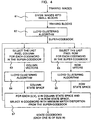
- FIG. 4 is shown a flow diagram, the process by which the super codebook and all the state codebooks extracted therefrom are designed.
- the training images should be selected to be statistically similar in some essential characteristic to those images which are to be transmitted. These are called the training images.
- these training images are divided into small blocks in step 61. These training blocks are then clustered via the Lloyd clustering algorithm.
- the final result of the clustering process is to allow us to construct a super codebook of vector quantized codes, e.g., 1,024 of them.
- the next step for assembling state codebooks from the super codebook we begin to extract the characteristics that will allow one to select from the super codebook various components for the state codebooks.
- step 63 The first step in this process is illustrated in step 63 which involves the selection of the last pixel column for each codeword which is representing a block in the super codebook. These sets of last pixel columns are clustered according to the Lloyd clustering algorithm in step 64.
- the information in the clustered codewords is organized as follows: For each u and v respectively, which are pair of values for which u is in the column state space and v is in the row state space, we select the N codewords with minimum match distortion from the super codebook.
- the selection of codewords with minimum match distortion as required in step 67 involves match distortion computation and search which are computation intensive, to construct, for example, 16,000 state codebooks. It is advantageous that this intensive calculation is achieved with analogous images prior to the real time operation of transmitter 10 of FIG. 1.
- step 71 divides the input image to be transmitted into small blocks of four by four pixels.
- step 72 finds the nearest neighbor of codeword in the current state book, according to the minimum mean square error nearest neighbor search technique already described.
- the resulting codeword index derived from the state codebook is then reconverted to its codeword in step 73 in order to provide the historical image statistics needed for my minimum edge discontinuity or minimum overlap discontinuity techniques as mathematically above described.
- the codeword index is also applied to the transmission binary encoding step 74 to allow the assignment of variable length noiseless binary codeword to the index in step 75.
- step 81 introduces a one-block delay so that the encoded block to the left of the currently encoded pixel block x is to be represented during the encoding of x . That encoded block immediately to the left of pixel block x is in the last previous pixel column, this being the nearest neighbor in the column state space as stated in step 83.
- side-match vector quantization the pixel blocks of the images are not overlapped so that rows 1,2,3 and 4 represent the first set of blocks, rows 5,6,7 and 8 represent the second of blocks, etc., and a similar principle applies for columns.
- rows 1,2,3 and 4 represent the first set of blocks
- rows 4,5,6 and 7 represent the second set of blocks, so that the pixels in row 4 now get encoded into different blocks sequentially after appropriate delays in such a way as to minimize the degree of intensity change in their encoding from row to row.
- the change is minimized by the overlap but some change is forced by the fact that other values are present in the block, for example, from row 3.
Landscapes
- Engineering & Computer Science (AREA)
- Multimedia (AREA)
- Signal Processing (AREA)
- Physics & Mathematics (AREA)
- General Physics & Mathematics (AREA)
- Theoretical Computer Science (AREA)
- Compression, Expansion, Code Conversion, And Decoders (AREA)
- Compression Or Coding Systems Of Tv Signals (AREA)
Claims (8)
- Verfahren zum Codieren eines Signals zum Bilden eines codierten Signals, wobei das Signal einen bestimmten Block in einer Gruppe von in Zeilen und Spalten angeordneten Blöcken darstellt, wobei jeder Block in der Gruppe von Blöcken eine Gruppe von ebenfalls in Zeilen und Spalten angeordneten Bildpunkten umfaßt [und das Verfahren folgende Schritte umfaßt]:a. Auswählen, allein basierend auf dem Block, der sich in den mehreren Blöcken zwar in der gleichen Spalte wie der bestimmte Block, aber in der unmittelbar vorangehenden Zeile befindet, und basierend auf dem Block, der sich in den mehreren Blöcken zwar in der dem bestimmten Block unmittelbar vorangehenden Spalte, aber in der gleichen Zeile befindet, eines Codelexikons aus mehreren Codelexika, wobei jedes Codelexikon Codeworte umfaßt und wobei jedes Codewort einen zugeordneten Index aufweist;b. Auswählen, basierend auf einem vorbestimmten Fehlerkriterium, eines Codewortes, das dem bestimmten Block am nächsten kommt, in dem ausgewählten Codelexikon;c. Bilden des codierten Signals auf der Basis des dem ausgewählten Codewort zugeordneten Indexes; undd. Übertragen des codierten Signals über einen Nachrichtenkanal;
dadurch gekennzeichnet, daß
das Auswählen eines Codelexikons allein auf der Basis der letzten Zeile von Bildpunkten in dem Block, der sich in den mehreren Blöcken zwar in der gleichen Spalte wie der bestimmte Block, aber in der unmittelbar vorangehenden Zeile befindet, und der letzten Spalte von Bildpunkten in dem Block, der sich in den mehreren Blöcken zwar in der dem bestimmten Block unmittelbar vorangehenden Spalte, aber in der gleichen Zeile befindet, erfolgt. - Verfahren nach Anspruch 1, wobei der Schritt des Auswählens eines Codelexikons folgende Schritte umfaßt:a. Bilden eines ersten Codewortes basierend auf einem ersten Index, wobei der erste Index demjenigen Codewort in dem Codelexikon zugeordnet ist, das dazu verwendet wird, den Block zu codieren, der sich zwar in der gleichen Spalte wie der bestimmte Block, aber in der unmittelbar vorangehenden Zeile befindet;b. Bilden eines zweiten Codewortes basierend auf einem zweiten Index, wobei der zweite Index demjenigen Codewort in dem Codelexikon zugeordnet ist, das dazu verwendet wird, den Block zu codieren, der sich zwar in der dem bestimmten Block unmittelbar vorangehenden Spalte, aber in der gleichen Zeile befindet;c. Erzeugen eines Zeilenzustandsausgangssignals durch Verzögern des ersten Codewortes um eine Zeile und Filtern des ersten Codewortes, um nur die letzte Zeile von Bildpunkten in der Gruppe von Bildpunkten in dem Block durchzulassen, der sich zwar in der gleichen Spalte wie der bestimmte Block, aber in der unmittelbar vorangehenden Zeile befindet;d. Erzeugen eines Spaltenzustandsausgangssignals durch Verzögern des zweiten Codewortes um eine Spalte und Filtern des zweiten Codewortes, um nur die letzte Spalte von Bildpunkten in der Gruppe von Bildpunkten in dem Block durchzulassen, der sich zwar in der dem bestimmten Block unmittelbar vorangehenden Spalte, aber in der gleichen Zeile befindet;e. Auswählen des Codelexikons basierend auf dem Zeilenzustandsausgangssignal und den Spaltenzustandsausgangssignalen.
- Verfahren nach Anspruch 1, wobei der Schritt des Auswählens eines Codewortes folgende Schritte umfaßt:a. Erzeugen eines Supercodelexikons basierend auf einer von einer Menge von Lernblöcken abgeleiteten Menge von Codeworten, wobei jeder der Lernblöcke eine Gruppe von Bildpunkten umfaßt, undb. Erzeugen mehrerer Codelexika aus dem Supercodelexikon durch ein Verfahren, das folgende Schritte umfaßt:i. Paarbildung zwischen demjenigen Teil jedes der Codeworte in den Lernblöcken, der die letzte Zeile von Bildpunkten in den Lernblöcken darstellt, und demjenigen Teil jedes der Codeworte in den Lernblöcken, der die letzte Spalte von Bildpunkten in den Lernblöcken darstellt,ii. Auswählen, für jedes der Paare, einer gemäß einem Fehlerkriterium am besten zu dem Paar passenden Untermenge der Menge von Codeworten, wobei die Untermenge von Codeworten das jedem der Paare zugeordnete Codelexikon bildet, undiii. weiteres Auswählen einer Untermenge der Codelexika, wobei die Codeworte jedes der ausgewählten Codelexika in der Untermenge von Codelexika einem Verzerrungsmaß genügen.
- Verfahren zum Decodieren eines von einem Nachrichtenkanal empfangenen Signals zum Bilden eines decodierten Signals, wobei das Signal einen einem Codewort zugeordneten Index darstellt, wobei das Codewort einen bestimmten Block in einer Gruppe von in Zeilen und Spalten angeordneten Blöcken darstellt, wobei jeder Block eine Gruppe von ebenfalls in Zeilen und Spalten angeordneten Bildpunkten umfaßt und das Verfahren folgende Schritte umfaßt:a. Empfangen des Signals von dem Nachrichtenkanal;b. Auswählen eines Codelexikons aus mehreren Codelexika, wobei in jedem Codelexikon mehrere Codeworte gespeichert sind und wobei ein Index jedes der Codeworte identifiziert, wobei das Auswählen allein auf der Basis der Blockzeile, die sich zwar in der gleichen Spalte wie der bestimmte Block, aber in der unmittelbar vorangehenden Zeile befindet, und auf der Basis des Blocks, der sich in der dem bestimmten Block zwar unmittelbar vorangehenden Spalte, aber in der gleichen Zeile befindet, erfolgt;c. Bestimmen des Codewortes für den bestimmten, von dem Index identifizierten Block nur aus den Codeworten in dem ausgewählten Codelexikon; undd. Bilden des decodierten, Codewort-basierenden Signals;
dadurch gekennzeichnet, daß
das Auswählen allein auf der Basis der letzten Zeile von Bildpunkten im Block, der sich zwar in der gleichen Spalte wie der bestimmte Block, aber in der unmittelbar vorangehenden Zeile befindet, und auf der Basis der letzten Spalte von Bildpunkten im Block, der sich zwar in der dem bestimmten Block unmittelbar vorangehenden Spalte, aber in der gleichen Zeile befindet, erfolgt. - Verfahren nach Anspruch 4, wobei der Schritt des Auswählens eines Codelexikons folgende Schritte umfaßt:a. Bilden eines ersten Codewortes basierend auf einem ersten Index, wobei der erste Index demjenigen Codewort in dem Codelexikon zugeordnet ist, das dazu verwendet wird, den Block zu codieren, der zwar sich in der gleichen Spalte wie der bestimmte Block, aber in der unmittelbar vorangehenden Zeile befindet;b. Bilden eines zweiten Codewortes basierend auf einem zweiten Index, wobei der zweite Index demjenigen Codewort in dem Codelexikon zugeordnet ist, das dazu verwendet wird, den Block zu codieren, der sich zwar in der dem bestimmten Block unmittelbar vorangehenden Spalte, aber in der gleichen Zeile befindet;c. Erzeugen eines Zeilenzustandsausgangssignals durch Verzögern des ersten Codewortes um eine Zeile und Filtern des ersten Codewortes, um nur die letzte Zeile von Bildpunkten in der Gruppe von Bildpunkten in dem Block durchzulassen, der sich zwar in der gleichen Spalte wie der bestimmte Block, aber in der unmittelbar vorangehenden Zeile befindet;d. Erzeugen eines Spaltenzustandsausgangssignals durch Verzögern des zweiten Codewortes um eine Spalte und Filtern des zweiten Codewortes, um nur die letzte Spalte von Bildpunkten in der Gruppe von Bildpunkten in dem Block durchzulassen, der sich zwar in der dem bestimmten Block unmittelbar vorangehenden Spalte, aber in der gleichen Zeile befindet; unde. Auswählen des Codelexikons basierend auf dem Zeilenzustandsausgangssignal und den Spaltenzustandsausgangssignalen.
- Verfahren nach Anspruch 4, wobei der Schritt des Auswählens eines Codelexikons folgende Schritte umfaßt:a. Erzeugen eines Supercodelexikons basierend auf einer von einer Menge von Lernblöcken abgeleiteten Menge von Codeworten, wobei jeder der Lernblöcke eine Gruppe von Bildpunkten umfaßt; undb. Erzeugen mehrerer Codelexika aus dem Supercodelexikon durch ein Verfahren, das folgende Schritte umfaßt:i. Paarbildung zwischen demjenigen Teil jedes der Codeworte in dem Lernblock, der die letzte Zeile von Bildpunkten in den Lernblöcken darstellt, und demjenigen Teil jedes der Codeworte in den Lernblöcken, der die letzte Spalte von Bildpunkten in den Lernblöcken darstellt,ii. Auswählen, für jedes der Paare, einer gemäß einem Fehlerkriterium am besten zu dem Paar passenden Untermenge der Menge von Codeworten, wobei die Untermenge von Codeworten das jedem der Paare zugeordnete Codelexikon bildet, undiii. weiteres Auswählen einer Untermenge der Codelexika, wobei die Codeworte jedes der ausgewählten Codelexika in der Untermenge von Codelexika einem Verzerrungsmaß genügen.
- System zum Codieren eines Signals zum Bilden eines codierten Signals, wobei das Signal einen bestimmten Block in einer Gruppe von in Zeilen und Spalten angeordneten Blöcken darstellt, wobei jeder Block in der Gruppe von Blöcken eine Gruppe von ebenfalls in Zeilen und Spalten angeordneten Bildpunkten umfaßt und das System folgendes umfaßt:a. Mittel zum Auswählen, allein basierend auf dem Block, der sich in den mehreren Blöcken zwar in der gleichen Spalte wie der bestimmte Block, aber in der unmittelbar vorangehenden Zeile befindet, und auf dem Block, der sich in den mehreren Blöcken zwar in der dem bestimmten Block unmittelbar vorangehenden Spalte, aber in der gleichen Zeile befindet, eines Codelexikons aus mehreren Codelexika, wobei jedes Codelexikon Codeworte umfaßt und wobei jedes Codewort einen zugeordneten Index aufweist;b. Mittel zum Auswählen, basierend auf einem vorbestimmten Fehlerkriterium, eines Codewortes, das dem bestimmten Block am nächsten kommt, in dem ausgewählten Codelexikon;c. Mittel zum Bilden des codierten Signals auf der Basis des dem ausgewählten Codewort zugeordneten Indexes; undd. Mittel zum Übertragen des codierten Signals über einen Nachrichtenkanal;
dadurch gekennzeichnet, daß
das Mittel zum Auswählen eines Codelexikons angeordnet ist, um das allein auf der letzten Zeile von Bildpunkten in dem Block, der sich in den mehreren Blöcken zwar in der gleichen Spalte wie der bestimmte Block, aber in der unmittelbar vorangehenden Zeile befindet, und der letzten Spalte von Bildpunkten in dem Block, der sich in den mehreren Blöcken in der dem bestimmten Block zwar unmittelbar vorangehenden Spalte, aber in der gleichen Zeile befindet, basierende Codelexikon auszuwählen. - System zum Decodieren eines von einem Nachrichtenkanal empfangenen Signals zum Bilden eines decodierten Signals, wobei das Signal einen einem Codewort zugeordneten Index darstellt, wobei das Codewort einen bestimmten Block in einer Gruppe von Blöcken darstellt, wobei jeder Block eine Gruppe von Bildpunkten umfaßt und das System folgendes umfaßt:a. Mittel zum Empfangen des Signals von dem Nachrichtenkanal;b. Mittel zum Auswählen eines Codelexikons aus mehreren Codelexika, wobei in jedem Codelexikon mehrere Codeworte gespeichert sind und wobei ein Index jedes der Codeworte identifiziert, wobei das Auswählen allein auf der Basis des Blocks, der sich zwar in der gleichen Spalte wie der bestimmte Block, aber in der unmittelbar vorangehenden Zeile befindet, und auf der Basis des Blocks, der sich in der dem bestimmten Block zwar unmittelbar vorangehenden Spalte, aber in der gleichen Zeile befindet, erfolgt;c. Mittel zum Bestimmen des Codewortes für den bestimmten, von dem Index identifizierten Block nur aus den Codeworten in dem ausgewählten Codelexikon; undd. Mittel zum Bilden des decodierten Codewortbasierenden Signals,
dadurch gekennzeichnet, daß
das Mittel zum Auswählen angeordnet ist, das allein auf der letzten Zeile von Bildpunkten im Block, der sich zwar in der gleichen Spalte wie der bestimmte Block, aber in der unmittelbar vorangehenden Zeile befindet, und auf der Basis der letzten Spalte von Bildpunkten im Block, der sich zwar in der dem bestimmten Block unmittelbar vorangehenden Spalte, aber in der gleichen Zeile befindet, basierende Auswählen auszuführen.
Applications Claiming Priority (2)
| Application Number | Priority Date | Filing Date | Title |
|---|---|---|---|
| US27286088A | 1988-11-18 | 1988-11-18 | |
| US272860 | 1988-11-18 |
Publications (3)
| Publication Number | Publication Date |
|---|---|
| EP0369689A2 EP0369689A2 (de) | 1990-05-23 |
| EP0369689A3 EP0369689A3 (de) | 1992-07-22 |
| EP0369689B1 true EP0369689B1 (de) | 1996-07-24 |
Family
ID=23041616
Family Applications (1)
| Application Number | Title | Priority Date | Filing Date |
|---|---|---|---|
| EP89311643A Expired - Lifetime EP0369689B1 (de) | 1988-11-18 | 1989-11-10 | Vorrichtung zur Vektorquantisierung von Bildern |
Country Status (5)
| Country | Link |
|---|---|
| US (1) | US5444800A (de) |
| EP (1) | EP0369689B1 (de) |
| JP (1) | JPH07112279B2 (de) |
| CA (1) | CA1315392C (de) |
| DE (1) | DE68926876T2 (de) |
Families Citing this family (39)
| Publication number | Priority date | Publication date | Assignee | Title |
|---|---|---|---|---|
| FR2679720A1 (fr) * | 1991-07-24 | 1993-01-29 | Telediffusion Fse | Un procede de codage de signaux d'image hybride adaptatif. |
| US5696851A (en) * | 1993-04-30 | 1997-12-09 | Comsat Corporation | Codeword-dependent post-filtering for vector quantization-based image compression |
| KR950002458A (ko) * | 1993-06-02 | 1995-01-04 | 이헌조 | 영상신호의 압축/신장 장치 |
| JPH0787327A (ja) * | 1993-09-17 | 1995-03-31 | Fuji Xerox Co Ltd | 画像符号化装置 |
| JP3013698B2 (ja) * | 1994-04-20 | 2000-02-28 | 松下電器産業株式会社 | ベクトル量子化符号化装置と復号化装置 |
| EP0768002B1 (de) * | 1994-06-27 | 1998-09-23 | Kodak Limited | Kompressions- und expansionsalgorithmus mit verlusten für bilddarstellungsdaten |
| JP3540855B2 (ja) * | 1995-03-08 | 2004-07-07 | シャープ株式会社 | ブロック歪み補正器 |
| US6404923B1 (en) * | 1996-03-29 | 2002-06-11 | Microsoft Corporation | Table-based low-level image classification and compression system |
| US6075470A (en) * | 1998-02-26 | 2000-06-13 | Research In Motion Limited | Block-wise adaptive statistical data compressor |
| US6330531B1 (en) * | 1998-08-24 | 2001-12-11 | Conexant Systems, Inc. | Comb codebook structure |
| US6546049B1 (en) * | 1998-10-05 | 2003-04-08 | Sarnoff Corporation | Parameterized quantization matrix adaptation for video encoding |
| WO2002017538A2 (en) * | 2000-08-18 | 2002-02-28 | The Regents Of The University Of California | Fixed, variable and adaptive bit rate data source encoding (compression) method |
| US6985633B2 (en) * | 2001-03-26 | 2006-01-10 | Ramot At Tel Aviv University Ltd. | Device and method for decoding class-based codewords |
| US6798360B1 (en) * | 2003-06-27 | 2004-09-28 | Canadian Space Agency | Method and system for compressing a continuous data flow in real-time using recursive hierarchical self-organizing cluster vector quantization (HSOCVQ) |
| SE0401850D0 (sv) * | 2003-12-19 | 2004-07-08 | Ericsson Telefon Ab L M | Image processing |
| SE526226C2 (sv) * | 2003-12-19 | 2005-08-02 | Ericsson Telefon Ab L M | Bildbehandling |
| KR100718134B1 (ko) * | 2005-07-21 | 2007-05-14 | 삼성전자주식회사 | 비트율에 적응적인 영상 데이터 이진 산술 부호화/복호화장치 및 방법 |
| US7627182B2 (en) * | 2005-12-30 | 2009-12-01 | Intel Corporation | Method and apparatus for varied format encoding and decoding of pixel data |
| EP2005614A4 (de) * | 2006-03-17 | 2012-02-22 | Nortel Networks Ltd | Mimo-systeme und verfahren mit geschlossener schleife |
| US7787691B2 (en) * | 2006-04-11 | 2010-08-31 | Telefonaktiebolaget Lm Ericsson (Publ) | High quality image processing |
| JP2008017304A (ja) * | 2006-07-07 | 2008-01-24 | Nippon Hoso Kyokai <Nhk> | 画像符号化装置、画像復号装置、画像符号化方法、及び画像符号化するプログラム |
| US8385670B2 (en) | 2008-08-20 | 2013-02-26 | Microsoft Corporation | Image restoration by vector quantization utilizing visual patterns |
| US8555145B2 (en) * | 2008-09-04 | 2013-10-08 | Apple Inc. | Systems and methods of encoding using a reduced codebook with adaptive resetting |
| US8559733B2 (en) * | 2009-03-31 | 2013-10-15 | Citrix Systems, Inc. | Methods and systems for approximating progressive image encoding using image partitioning |
| US8581757B2 (en) * | 2009-07-02 | 2013-11-12 | Siemens Enterprise Communications Gmbh & Co. Kg | Method for vector quantization of a feature vector |
| US9106933B1 (en) | 2010-05-18 | 2015-08-11 | Google Inc. | Apparatus and method for encoding video using different second-stage transform |
| US9210442B2 (en) | 2011-01-12 | 2015-12-08 | Google Technology Holdings LLC | Efficient transform unit representation |
| US9380319B2 (en) | 2011-02-04 | 2016-06-28 | Google Technology Holdings LLC | Implicit transform unit representation |
| US9219915B1 (en) | 2013-01-17 | 2015-12-22 | Google Inc. | Selection of transform size in video coding |
| US9967559B1 (en) | 2013-02-11 | 2018-05-08 | Google Llc | Motion vector dependent spatial transformation in video coding |
| US9544597B1 (en) | 2013-02-11 | 2017-01-10 | Google Inc. | Hybrid transform in video encoding and decoding |
| US9674530B1 (en) | 2013-04-30 | 2017-06-06 | Google Inc. | Hybrid transforms in video coding |
| US9565451B1 (en) | 2014-10-31 | 2017-02-07 | Google Inc. | Prediction dependent transform coding |
| US9769499B2 (en) | 2015-08-11 | 2017-09-19 | Google Inc. | Super-transform video coding |
| US10277905B2 (en) | 2015-09-14 | 2019-04-30 | Google Llc | Transform selection for non-baseband signal coding |
| US9807423B1 (en) | 2015-11-24 | 2017-10-31 | Google Inc. | Hybrid transform scheme for video coding |
| US11308152B2 (en) * | 2018-06-07 | 2022-04-19 | Canon Kabushiki Kaisha | Quantization method for feature vector, search method, apparatus and storage medium |
| US11122297B2 (en) | 2019-05-03 | 2021-09-14 | Google Llc | Using border-aligned block functions for image compression |
| CN111741307B (zh) * | 2020-06-09 | 2023-06-06 | 绍兴图信科技有限公司 | 基于矢量量化压缩和线性回归预测的图像压缩方法 |
Family Cites Families (10)
| Publication number | Priority date | Publication date | Assignee | Title |
|---|---|---|---|---|
| US4578704A (en) * | 1983-06-20 | 1986-03-25 | At&T Bell Laboratories | Image coding technique |
| FR2554995B1 (fr) * | 1983-11-15 | 1989-05-05 | Thomson Cgr | Procede de compression d'une succession d'informations numeriques et dispositif mettant en oeuvre ce procede |
| US4646356A (en) * | 1984-06-29 | 1987-02-24 | International Business Machines Corporation | Method for converting a bit map of an image to a run length or run end representation |
| JPS6232785A (ja) * | 1985-08-05 | 1987-02-12 | Fujitsu Ltd | 適応形ベクトル量子化方式 |
| JPS62166655A (ja) * | 1986-01-20 | 1987-07-23 | Nippon Telegr & Teleph Corp <Ntt> | 自己トレ−ニング機能を有するベクトル量子化方式 |
| JPS62222783A (ja) * | 1986-03-24 | 1987-09-30 | Kokusai Denshin Denwa Co Ltd <Kdd> | 動画像の高能率符号化方式 |
| JPH082104B2 (ja) * | 1986-11-10 | 1996-01-10 | 富士通株式会社 | 動き補償フレ−ム間符号化方式 |
| JPS63169878A (ja) * | 1987-01-08 | 1988-07-13 | Ricoh Co Ltd | 画像デ−タのベクトル符号化方式 |
| US4791654A (en) * | 1987-06-05 | 1988-12-13 | American Telephone And Telegraph Company, At&T Bell Laboratories | Resisting the effects of channel noise in digital transmission of information |
| US4811112A (en) * | 1987-07-24 | 1989-03-07 | American Telephone And Telegraph Company, At&T Bell Laboratories | Vector DPCM image coding method and apparatus |
-
1989
- 1989-09-21 CA CA000612366A patent/CA1315392C/en not_active Expired - Fee Related
- 1989-11-10 EP EP89311643A patent/EP0369689B1/de not_active Expired - Lifetime
- 1989-11-10 DE DE68926876T patent/DE68926876T2/de not_active Expired - Fee Related
- 1989-11-17 JP JP1297794A patent/JPH07112279B2/ja not_active Expired - Fee Related
-
1994
- 1994-03-14 US US08/213,472 patent/US5444800A/en not_active Expired - Fee Related
Also Published As
| Publication number | Publication date |
|---|---|
| DE68926876D1 (de) | 1996-08-29 |
| CA1315392C (en) | 1993-03-30 |
| US5444800A (en) | 1995-08-22 |
| JPH07112279B2 (ja) | 1995-11-29 |
| EP0369689A2 (de) | 1990-05-23 |
| DE68926876T2 (de) | 1996-12-19 |
| EP0369689A3 (de) | 1992-07-22 |
| JPH02183684A (ja) | 1990-07-18 |
Similar Documents
| Publication | Publication Date | Title |
|---|---|---|
| EP0369689B1 (de) | Vorrichtung zur Vektorquantisierung von Bildern | |
| US5903676A (en) | Context-based, adaptive, lossless image codec | |
| JP2823770B2 (ja) | マルチレベル信号の符号化方法 | |
| CA2181017C (en) | Method and apparatus for encoding and decoding an image | |
| US6072909A (en) | Image coding devise and image decoding devise using with image disassembly | |
| US5444488A (en) | Method and apparatus for coding digital data using vector quantizing techniques | |
| US7574354B2 (en) | Transcoding between the indices of multipulse dictionaries used in compressive coding of digital signals | |
| Effros et al. | Variable dimension weighted universal vector quantization and noiseless coding | |
| US20030081852A1 (en) | Encoding method and arrangement | |
| Xin et al. | Soft compression: An approach to shape coding for images | |
| Kumar et al. | Vector quantization with codebook and index compression | |
| Cheng et al. | Robust zero-redundancy vector quantization for noisy channels | |
| Kuo et al. | Noise reduction of VQ encoded images through anti-gray coding | |
| Tsai et al. | A new dynamic finite-state vector quantization algorithm for image compression | |
| Gray et al. | Image compression and tree-structured vector quantization | |
| Effros | Robustness to channel variation in source coding for transmission across noisy channels | |
| KR100216600B1 (ko) | 영상 신호 벡터 양자화기를 위한 다중 부호어 전송 방법 | |
| Onno et al. | Data-rate constrained lattice vector quantization: a new quantizing algorithm in a rate-distortion sense | |
| JP2622140B2 (ja) | 画像伝送方法 | |
| JP2001309380A (ja) | 画像信号符号化装置/復号装置,画像信号符号化方法/復号方法および画像信号符号化/復号プログラム記録媒体 | |
| JP2943925B2 (ja) | 画像符号化方法 | |
| Bardekar et al. | A review on LBG algorithm for image compression | |
| Chaddha et al. | Finite state hierarchical table-lookup vector quantization for images | |
| KR100613107B1 (ko) | 벡터양자화(vq) 코드북을 최적화하는 방법과 채널 qam신호를 최적화하는 방법, 그리고 vq코드북 및 qam신호를 동시에 최적화하는 방법 | |
| Hamzaoui et al. | Quadtree based variable rate oriented mean shape-gain vector quantization |
Legal Events
| Date | Code | Title | Description |
|---|---|---|---|
| PUAI | Public reference made under article 153(3) epc to a published international application that has entered the european phase |
Free format text: ORIGINAL CODE: 0009012 |
|
| AK | Designated contracting states |
Kind code of ref document: A2 Designated state(s): DE FR GB IT SE |
|
| PUAL | Search report despatched |
Free format text: ORIGINAL CODE: 0009013 |
|
| AK | Designated contracting states |
Kind code of ref document: A3 Designated state(s): DE FR GB IT SE |
|
| 17P | Request for examination filed |
Effective date: 19930107 |
|
| RAP3 | Party data changed (applicant data changed or rights of an application transferred) |
Owner name: AT&T CORP. |
|
| 17Q | First examination report despatched |
Effective date: 19950113 |
|
| GRAH | Despatch of communication of intention to grant a patent |
Free format text: ORIGINAL CODE: EPIDOS IGRA |
|
| GRAH | Despatch of communication of intention to grant a patent |
Free format text: ORIGINAL CODE: EPIDOS IGRA |
|
| GRAA | (expected) grant |
Free format text: ORIGINAL CODE: 0009210 |
|
| AK | Designated contracting states |
Kind code of ref document: B1 Designated state(s): DE FR GB IT SE |
|
| ITF | It: translation for a ep patent filed | ||
| REF | Corresponds to: |
Ref document number: 68926876 Country of ref document: DE Date of ref document: 19960829 |
|
| ET | Fr: translation filed | ||
| PLBE | No opposition filed within time limit |
Free format text: ORIGINAL CODE: 0009261 |
|
| STAA | Information on the status of an ep patent application or granted ep patent |
Free format text: STATUS: NO OPPOSITION FILED WITHIN TIME LIMIT |
|
| 26N | No opposition filed | ||
| PGFP | Annual fee paid to national office [announced via postgrant information from national office to epo] |
Ref country code: FR Payment date: 19980915 Year of fee payment: 10 |
|
| PGFP | Annual fee paid to national office [announced via postgrant information from national office to epo] |
Ref country code: SE Payment date: 19980921 Year of fee payment: 10 |
|
| PGFP | Annual fee paid to national office [announced via postgrant information from national office to epo] |
Ref country code: GB Payment date: 19980930 Year of fee payment: 10 |
|
| PGFP | Annual fee paid to national office [announced via postgrant information from national office to epo] |
Ref country code: DE Payment date: 19981231 Year of fee payment: 10 |
|
| PG25 | Lapsed in a contracting state [announced via postgrant information from national office to epo] |
Ref country code: GB Free format text: LAPSE BECAUSE OF NON-PAYMENT OF DUE FEES Effective date: 19991110 |
|
| PG25 | Lapsed in a contracting state [announced via postgrant information from national office to epo] |
Ref country code: SE Free format text: LAPSE BECAUSE OF NON-PAYMENT OF DUE FEES Effective date: 19991111 |
|
| GBPC | Gb: european patent ceased through non-payment of renewal fee |
Effective date: 19991110 |
|
| EUG | Se: european patent has lapsed |
Ref document number: 89311643.4 |
|
| PG25 | Lapsed in a contracting state [announced via postgrant information from national office to epo] |
Ref country code: FR Free format text: LAPSE BECAUSE OF NON-PAYMENT OF DUE FEES Effective date: 20000731 |
|
| PG25 | Lapsed in a contracting state [announced via postgrant information from national office to epo] |
Ref country code: DE Free format text: LAPSE BECAUSE OF NON-PAYMENT OF DUE FEES Effective date: 20000901 |
|
| REG | Reference to a national code |
Ref country code: FR Ref legal event code: ST |
|
| PG25 | Lapsed in a contracting state [announced via postgrant information from national office to epo] |
Ref country code: IT Free format text: LAPSE BECAUSE OF NON-PAYMENT OF DUE FEES;WARNING: LAPSES OF ITALIAN PATENTS WITH EFFECTIVE DATE BEFORE 2007 MAY HAVE OCCURRED AT ANY TIME BEFORE 2007. THE CORRECT EFFECTIVE DATE MAY BE DIFFERENT FROM THE ONE RECORDED. Effective date: 20051110 |