EP0370136A1 - Schmiermittelfördereinrichtung - Google Patents
Schmiermittelfördereinrichtung Download PDFInfo
- Publication number
- EP0370136A1 EP0370136A1 EP88121065A EP88121065A EP0370136A1 EP 0370136 A1 EP0370136 A1 EP 0370136A1 EP 88121065 A EP88121065 A EP 88121065A EP 88121065 A EP88121065 A EP 88121065A EP 0370136 A1 EP0370136 A1 EP 0370136A1
- Authority
- EP
- European Patent Office
- Prior art keywords
- pressure
- filter
- lubricant
- pump
- relief valve
- Prior art date
- Legal status (The legal status is an assumption and is not a legal conclusion. Google has not performed a legal analysis and makes no representation as to the accuracy of the status listed.)
- Granted
Links
- 239000000314 lubricant Substances 0.000 title claims abstract description 44
- 230000003068 static effect Effects 0.000 claims abstract description 4
- 238000012806 monitoring device Methods 0.000 claims description 6
- 238000005086 pumping Methods 0.000 claims description 4
- 230000000903 blocking effect Effects 0.000 claims description 2
- 238000010586 diagram Methods 0.000 description 4
- 239000000945 filler Substances 0.000 description 4
- 238000005461 lubrication Methods 0.000 description 4
- 238000004140 cleaning Methods 0.000 description 3
- 238000011109 contamination Methods 0.000 description 2
- 239000012530 fluid Substances 0.000 description 2
- 239000004519 grease Substances 0.000 description 2
- 230000001771 impaired effect Effects 0.000 description 1
- 230000003287 optical effect Effects 0.000 description 1
- 239000002245 particle Substances 0.000 description 1
- 238000011144 upstream manufacturing Methods 0.000 description 1
Images

Classifications
-
- F—MECHANICAL ENGINEERING; LIGHTING; HEATING; WEAPONS; BLASTING
- F16—ENGINEERING ELEMENTS AND UNITS; GENERAL MEASURES FOR PRODUCING AND MAINTAINING EFFECTIVE FUNCTIONING OF MACHINES OR INSTALLATIONS; THERMAL INSULATION IN GENERAL
- F16N—LUBRICATING
- F16N39/00—Arrangements for conditioning of lubricants in the lubricating system
- F16N39/06—Arrangements for conditioning of lubricants in the lubricating system by filtration
-
- F—MECHANICAL ENGINEERING; LIGHTING; HEATING; WEAPONS; BLASTING
- F16—ENGINEERING ELEMENTS AND UNITS; GENERAL MEASURES FOR PRODUCING AND MAINTAINING EFFECTIVE FUNCTIONING OF MACHINES OR INSTALLATIONS; THERMAL INSULATION IN GENERAL
- F16N—LUBRICATING
- F16N7/00—Arrangements for supplying oil or unspecified lubricant from a stationary reservoir or the equivalent in or on the machine or member to be lubricated
- F16N7/38—Arrangements for supplying oil or unspecified lubricant from a stationary reservoir or the equivalent in or on the machine or member to be lubricated with a separate pump; Central lubrication systems
- F16N7/385—Central lubrication systems
-
- F—MECHANICAL ENGINEERING; LIGHTING; HEATING; WEAPONS; BLASTING
- F16—ENGINEERING ELEMENTS AND UNITS; GENERAL MEASURES FOR PRODUCING AND MAINTAINING EFFECTIVE FUNCTIONING OF MACHINES OR INSTALLATIONS; THERMAL INSULATION IN GENERAL
- F16N—LUBRICATING
- F16N2270/00—Controlling
- F16N2270/60—Pressure
- F16N2270/62—Limit
Definitions
- the invention relates to a lubricant delivery device, which has the features of the preamble of claim 1, for the lubricant supply of at least one metering valve in a static or dynamic single or multi-line system.
- a filter is arranged in the main line, that is to say the section of the lubricant line lying between the metering valve or the metering valves on the one hand and the pressure and relief valve of the lubricant delivery device on the other hand.
- This can prevent dirt from getting into the metering valves and the lubrication points.
- the more the filter becomes clogged with dirt over the course of time the more the proper functioning of the metering valves is impaired, with the result that the quantity of lubricant dispensed by the metering valves has a considerable scatter in relation to the nominal metering quantity or the metering valves become inoperable.
- the invention has for its object to improve the known statistical and dynamic single and multi-line systems in such a way that a proper functioning of each existing metering valve is ensured.
- This object is achieved according to the invention with a lubricant delivery device which has the features of claim 1.
- the lubricant delivery device makes it possible to dispense with a filter in the main line because all of the oil delivered by the pump is filtered by means of the filter located in the delivery line between the pump and the pressure and relief valve. Since this filter is arranged upstream of the pressure and relief valve, the condition of the filter, that is, the degree to which it is clogged by dirt particles, has no influence whatsoever on the pressure prevailing at the outlet of the pressure and relief valve. With increasing contamination, the filter only increases the flow resistance in the delivery line between the pump and the pressure and relief valve, which does not affect the proper functioning of the lubricant delivery device to a certain extent.
- the pressure drop in the filter is monitored by means of two pressure sensors arranged according to claim 2 and a differential pressure monitoring device. It is particularly advantageous that the filter can be changed or cleaned without having to switch off the lubrication system, because the change or cleaning can take place during the pause during which the pressure and relief valve separates the delivery line from the main line. It is therefore expedient to do this early enough cleaning or replacement of the filter is reported by the differential pressure monitoring device that it is possible to wait until the next pause, in order to then replace or clean the filter.
- the lubricant delivery device is equipped with a manometer according to claim 3. Furthermore, a pressure relief valve according to claim 4 is provided for safety reasons.
- the pump can be switched from pumping to suction and vice versa.
- the pump then only needs to be switched to suction mode for a short time, as a result of which only the direction of rotation of the drive motor needs to be changed, which can be done automatically by a control device.
- a check valve bridging the filter and blocking in the direction from the pump to the metering valve connection is provided in a preferred embodiment. The connection of this check valve to the delivery line is preferably carried out according to claim 6 or claim 7.
- a lubricant delivery device for the lubricant supply of at least one metering valve in a static or dynamic single or multi-line system has a housing 1 in which all the components mentioned below are contained.
- a filler line 3 leads to a lubricant reservoir 2, the end of which is remote from the reservoir 2 is connected to a filler neck 4 arranged in the housing wall, which can be closed and opened from the outside by means of a manually operable closure cap.
- a pump 5 which can be driven by an electric motor 6 is, promotes lubricant from the reservoir 2 into a delivery line 7, which leads to a connection device 8 for the main line of the system.
- a lubricant filter 9 is interchangeably arranged in the delivery line 7.
- the housing 1 for the reception of the filter 9 has a cylindrical receptacle 10 which is accessible from the outside and which can be closed tightly by means of a screw cap 11.
- the longitudinal axis of the receptacle 10 is inclined downward into the housing 1, as a result of which lubricant is prevented from escaping when the filter 9 is changed.
- a filter change therefore takes only little time, so that it is possible without a shutdown of the lubrication system during a break.
- the inclined region 12 of the wall of the housing 1, to which the receptacle 10 is connected, has the filler neck 4 at a distance next to the receptacle 10, which has a shape like the receptacle 10. It is therefore easy to fill in the lubricant.
- the delivery line 7 leads from the outlet side of the filter 9 to a pressure and relief valve 13, by means of which, in a known manner, the change between intervals for the proper functioning of the metering valves in the system (not shown) to which the lubricant pressure is applied to the metering valves, and intervals are effected in which the main line leading to the metering valves is relieved of pressure.
- a pressure relief valve 15 is located, which releases the flow through the relief line 14 to the reservoir 2 from a minimum value of the pressure.
- the delivery line 7 leads from the pressure and relief valve 13 to the connection device 8 for the main line.
- a pressure gauge 17 and a first pressure sensor 18 are connected to the delivery line 7.
- the pressure gauge 17 is arranged next to the screw cap in the area 12 of the housing 1.
- the first pressure sensor 18, which generates an electrical signal corresponding to the pressure in the delivery line 7, is connected to a differential pressure monitoring device, not shown.
- the pressure drop across the filter 9 is determined by means of the two pressure sensors 18 and 19 and the differential pressure monitoring device.
- this pressure drop has reached a value which makes it necessary to replace the filter or to clean the filter 9, this is indicated by a corresponding signal from the differential pressure monitoring device.
- the filter can be exchanged or cleaned without the lubrication system having to be switched off.
- a level sensor 20 controls the level of lubricant in the reservoir 2 and triggers a signal as soon as the level falls below a lower limit value so that lubricant can be introduced into the filler neck 4 in good time. Furthermore, for safety reasons, a pressure relief valve 21 is provided which is located in a return line 22 which is connected to the Delivery line 7 is connected between the filter 9 and the pressure and relief valve 13 and leads to the reservoir 2.
- the second exemplary embodiment of the lubricant conveying device according to the invention differs from the exemplary embodiment described above only in the possibility of rapid relief of the connected single-line or multi-line system, which is particularly advantageous if the lubricant is a viscous oil or fluid grease. Since the second exemplary embodiment coincides with the first exemplary embodiment, only the differences are explained below. With regard to the corresponding parts, reference is made to the explanations for the first exemplary embodiment, which is why the same reference numbers are used in FIG. 3 for the corresponding parts.
- the motor 6 is assigned a reversing direction of rotation switch 24 which can be controlled by the control device, not shown.
- the direction reversal switch 24 is actuated briefly, as a result of which the pump 5 switches to suction operation for this period of time. So that the lubricant cannot be sucked through the lubricant filter 9 to the pump during the suction operation of the pump 5, the lubricant filter 9 is bridged by a check valve 23.
- the check valve 23 is connected on the one hand between the pump 5 and the second pressure sensor 19 and on the other hand between the lubricant filter 9 and the pressure relief valve 21 to the delivery line 7, in such a way that it is in the direction from the pump 5 to the connecting device 8 locks out. That is why during pump operation Do not flow lubricant through the check valve 23. If, however, the pump 5 is switched to suction mode for rapid relief, the check valve 23 opens, so that the pressure generated by the pump 5 can be transmitted via the delivery line 7 to the connected system without a drop in pressure at the lubricant filter 9 to the pump 5 arises.
- the third exemplary embodiment shown in FIG. 4 differs from the exemplary embodiment according to FIG. 3 only in that the check valve 23 on the one hand between the lubricant filter 9 and the second pressure sensor 19 and on the other hand between the pressure relief valve 21 and the pressure and relief valve 13 to the delivery line 7 is connected.
- the pressure relief valve 23 blocks in the direction from the pump 5 to the connection device 8, so that the pumped lubricant must pass through the lubricant filter 9 without exception during the pumping operation.
- the check valve 23 is only opened during the brief suction operation of the pump 5 for the purpose of quick relief and thereby avoids a pressure drop at the lubricant valve 9 towards the pump 5.
- the lubricant does not flow through the lubricant filter 9 against the pump 5 during the suction operation of the pump 5, which, as in the exemplary embodiment according to FIG. 3, shortens the time required to apply the pressure at the connecting device 8 and thus lower in the connected system.
Landscapes
- Engineering & Computer Science (AREA)
- General Engineering & Computer Science (AREA)
- Mechanical Engineering (AREA)
- Coating Apparatus (AREA)
- Details Of Reciprocating Pumps (AREA)
- Lubrication Of Internal Combustion Engines (AREA)
- Details And Applications Of Rotary Liquid Pumps (AREA)
- Filling Or Discharging Of Gas Storage Vessels (AREA)
Abstract
Description
- Die Erfindung betrifft eine Schmiermittelfördereinrichtung, welche die Merkmale des Oberbegriffs des Anspruches 1 aufweist, für die Schmiermittelversorgung wenigstens eines Dosierventils in einer statischen oder dynamischen Ein- oder Mehrleitungsanlage.
- Bei den bekannten Anlagen dieser Art ist in der Hauptleitung, also dem zwischen dem Dosierventil oder den Dosierventilen einerseits und dem Druck- und Entlastungsventil der Schmiermittelfördereinrichtung andererseits liegenden Abschnitt der Schmiermittelleitung ein Filter angeordnet. Hierdurch läßt sich zwar verhindern, daß Schmutz in die Dosierventile und an die Schmierstellen gelangt. Je mehr sich aber im Laufe der Zeit das Filter mit Schmutz zusetzt, desto stärker wird die ordnungsgemäße Arbeitsweise der Dosierventile beeinträchtigt, was zur Folge hat, daß die von den Dosierventilen abgegebene Schmiermittelmenge eine erhebliche Streuung zur Nenndosiermenge haben oder die Dosierventile funktionsunfähig werden.
- Der Erfindung liegt die Aufgabe zugrunde, die bekannten statitischen und dynamischen Ein- und Mehrleitungsanlagen dahingehend zu verbessern, daß eine einwandfreie Arbeitsweise jedes vorhandenen Dosierventils sichergestellt ist. Diese Aufgabe wird erfindungsgemäß mit einer Schmiermittelfördereinrichtung gelöst, welche die Merkmale des Anspruches 1 aufweist.
- Die erfindungsgemäße Schmiermittelfördereinrichtung erlaubt es, auf ein Filter in der Hauptleitung zu verzichten, weil das gesamte von der Pumpe geförderte Öl mittels des in der Förderleitung zwischen der Pumpe und dem Druck- und Entlastungsventil liegenden Filters filtriert wird. Da dieses Filter vor dem Druck- und Entlastungsventil angeordnet ist, hat der Zustand des Filters, also der Grad, in dem es durch Schmutzpartikel zugesetzt ist, keinerlei Einfluß auf den am Ausgang des Druck- und Entlastungsventils herrschenden Druck. Das Filter erhöht mit zunehmender Verschmutzung nur den Strömungswiderstand in der Förderleitung zwischen der Pumpe und dem Druck- und Entlastungsventil, was bis zu einem gewissen Ausmaße die ordnungsgemäße Funktion der Schmiermittelfördereinrichtung nicht beeinträchtigt.
- Damit das Filter dann, wenn seine Verschmutzung die zulässige Grenze erreicht hat, ausgetauscht oder gereinigt werden kann, erfolgt bei einer bevorzugten Ausführungsform eine Überwachung des Druckabfalls im Filter mittels zweier gemäß Anspruch 2 angeordneter Drucksensoren und einer Differenzdruck-Überwachungseinrichtung. Von besonderem Vorteil ist, daß das Filter gewechselt oder gereinigt werden kann, ohne die Schmieranlage abschalten zu müssen, weil der Wechsel oder die Reinigung in der Pausenzeit erfolgen kann, in welcher das Druck- und Entlastungsventil die Förderleitung von der Hauptleitung trennt. Daher wird zweckmäßigerweise so frühzeitig die erforderlich werdende Reinigung oder Auswechslung des Filters von der Differenzdruck-Überwachungseinrichtung gemeldet, daß bis zur nächsten Pausenzeit gewartet werden kann, um dann das Filter auszutauschen oder zu reinigen.
- Zum Zwecke einer optischen Anzeige des in der Hauptleitung herrschenden Druckes ist bei einer vorteilhaften Ausführungsform die Schmiermittelfördereinrichtung mit einem Manometer gemäß Anspruch 3 ausgerüstet. Ferner ist aus Sicherheitsgründen ein Überdruckventil gemäß Anspruch 4 vorgesehen.
- Für eine selbsttätige Schnellentlastung des Dosierventils oder der Dosierventile, wie sie vor allem bei zähflüssigem Öl oder Fließfett erwünscht sein kann, kann man eine Umschaltbarkeit der Pumpe von Pumpbetrieb auf Saugbetrieb und umgekehrt vorsehen. Für die Schnellentlastung braucht dann nur kurzzeitig die Pumpe auf Saugbetrieb umgeschaltet zu werden, wodurch nur die Drehrichtung des Antriebsmotors geändert zu werden braucht, was automatisch von einer Steuereinrichtung aus erfolgen kann. Um während des Saugbetriebs der Pumpe zu verhindern, daß das Schmiermittel in Richtung gegen die Pumpe hin das Filter durchströmt, ist bei einer bevorzugten Ausführungsform ein das Filter überbrückendes und in Richtung von der Pumpe zum Dosierventilanschluß sperrendes Rückschlagventil vorgesehen. Der Anschluß dieses Rückschlagventils an die Förderleitung ist vorzugsweise gemäß Anspruch 6 oder Anspruch 7 ausgeführt.
- Im folgenden ist die Erfindung anhand von in der Zeichnung dargestellten Ausführungsbeispielen im einzelnen erläutert.
Es zeigen - Fig. 1 ein Schaltbild eines ersten Ausführungsbeispiels,
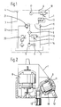
- Fig. 2 einen unvollständig dargestellten Schnitt des Ausführungsbeispiels,
- Fig. 3 ein Schaltbild eines zweiten Ausführungsbeispiels,
- Fig. 4 ein Schaltbild eines dritten Ausführungsbeispiels.
- Eine Schmiermittelfördereinrichtung für die Schmiermittelversorgung wenigstens eines Dosierventils in einer statischen oder dynamischen Ein- oder Mehrleitungsanlage weist ein Gehäuse 1 auf, in dem sämtliche nachfolgend erwähnten Bauteile enthalten sind. Zu einem Schmiermittel-Vorratsbehälter 2 führt eine Einfüllleitung 3, deren dem Vorratsbehälter 2 abgekehrtes Ende an einen in der Gehäusewand angeordneten Einfüllstutzen 4 angeschlossen ist, der von außen her mittels eines manuell betätigbaren Verschlußdeckels verschließbar ist und geöffnet werden kann. Eine Pumpe 5, die von einem Elektromotor 6 antreibbar ist, fördert Schmiermittel aus dem Vorratsbehälter 2 heraus in eine Förderleitung 7, die zu einer Anschlußvorrichtung 8 für die Hauptleitung der Anlage führt.
- In der Förderleitung 7 ist auswechselbar ein Schmiermittelfilter 9 angeordnet. Wie Fig.2 zeigt, weist das Gehäuse 1 für die Aufnahme des Filters 9 eine von außen her zugängliche, zylindrische Aufnahme 10 auf, die mittels eines Schraubdeckels 11 dicht verschließbar ist. Die Längsachse der Aufnahme 10 ist in das Gehäuse 1 hinein nach unten geneigt, wodurch ein Austritt von Schmiermittel beim Wechseln des Filters 9 vermieden wird. Für einen Filterwechsel oder eine Filterreinigung brauchen nur der Schraubdeckel 11 abgenommen und das Filter 9 aus dem am Grund der Aufnahme 10 vorgesehenen Innengewinde herausgedreht zu werden. Ein Filterwechsel nimmt deshalb nur wenig Zeit in Anspruch, so daß er während einer Pausenzeit ohne eine Abschaltung der Schmieranlage problemlos möglich ist.
- Der geneigt verlaufende Bereich 12 der Wand des Gehäuses 1, an den sich die Aufnahme 10 anschließt, weist im Abstand neben der Aufnahme 10 den Einfüllstutzen 4 auf, der eine Form wie die Aufnahme 10 hat. Das Einfüllen des Schmiermittels ist deshalb problemlos möglich.
- Wie die Fig.1 und 2 zeigen, führt die Förderleitung 7 von der Austrittseite des Filters 9 zu einem Druck- und Entlastungsventil 13, mittels dessen in bekannter Weise der für die ordnungsgemäße Arbeitsweise der Dosierventile in der nicht dargestellten Anlage der Wechsel zwischen Intervallen, in denen der Schmiermitteldruck an den Dosierventilen anliegt, und Intervallen bewirkt wird, in denen die zu den Dosierventilen führende Hauptleitung druckentlastet ist. Für diese Druckentlastung führt vom Druck- und Entlastungsventil 13 eine Entlastungsleitung 14 zum Vorratsbehälter 2, in der ein Überdruckventil 15 liegt, das ab einem Mindestwert des Druckes den Durchfluß durch die Entlastungsleitung 14 zum Vorratsbehälter 2 freigibt.
- Vom Druck- und Entlastungsventil 13 führt die Förderleitung 7 zu der Anschlußvorrichtung 8 für die Hauptleitung. In dem letztgenannten Abschnitt sind an die Förderleitung 7 ein Manometer 17 sowie ein erster Drucksensor 18 angeschlossen. Das Manometer 17 ist neben dem Schraubdeckel im Bereich 12 des Gehäuses 1 angeordnet. Der erste Drucksensor 18, der ein dem Druck in der Förderleitung 7 entsprechendes elektrisches Signal erzeugt, ist an eine nicht dargestellte Differenzdruck-Überwachungseinrichtung angeschlossen. Mit dieser Einrichtung ist auch der Signalausgang eines zweiten Drucksensors 19 verbunden, der wie der erste Drucksensor 18 ausgebildet ist, aber an die Förderleitung 7 zwischen der Pumpe 5 und dem Filter 9 angeschlossen ist. Mittels der beiden Drucksensoren 18 und 19 sowie der Differenzdruck-Überwachungseinrichtung wird der Druckabfall am Filter 9 ermittelt. Hat dieser Druckabfall einen Wert erreicht, der einen Filteraustausch oder ein Reinigen des Filters 9 erforderlich macht, dann wird dies durch ein entsprechendes Signal der Differenzdruck-Überwachungseinrichtung angezeigt. Bei einer der nächsten Pausenzeiten kann dann der Filteraustausch oder die Filterreinigung vorgenommen werden, ohne daß die Schmieranlage abgeschaltet werden müßte.
- Ein Niveausensor 20 kontrolliert das Schmiermittelniveau im Vorratsbehälter 2 und löst ein Signal aus, sobald das Niveau einen unteren Grenzwert unterschreitet, damit rechtzeitig Schmiermittel in den Einfüllstutzen 4 eingeleitet werden kann. Ferner ist aus Sicherheitsgründen ein Überdruckventil 21 vorgesehen, das in einer Rücklaufleitung 22 liegt, die an die Förderleitung 7 zwischen dem Filter 9 und dem Druck- und Entlastungsventil 13 angeschlossen ist und zum Vorratsbehälter 2 führt.
- Das zweite Ausführungsbeispiel der erfindungsgemäßen Schmiermittelfördereinrichtung, dessen Schaltbild in Fig .3 dargestellt ist, unterscheidet sich von dem vorstehend beschriebenen Ausführungsbeispiel nur durch die Möglichkeit der Schnellentlastung der angeschlossenen Ein- oder Mehrleitungsanlage, was insbesondere dann vorteilhaft ist, wenn es sich bei dem Schmiermittel um ein zähflüssiges Öl oder ein Fließfett handelt. Da im übrigen das zweite Ausführungsbeispiel mit dem ersten Ausführungsbeispiel übereinstimmt, sind im folgenden nur die Unterschiede erläutert. Hinsichtlich der übereinstimmenden Teile wird auf die Ausführungen zum ersten Ausführungsbeispiel Bezug genommen, weshalb auch in Fig.3 für die sich entsprechenden Teile gleiche Bezugszahlen verwendet sind.
- Um die Drehrichtung des Motors 6 umkehren und damit die Pumpe 5 von Pumpbetrieb auf Saugbetrieb und umgekehrt umschalten zu können, ist dem Motor 6 ein Drehrichtungsumkehrungs-Schalter 24 zugeordnet, der von der nicht dargestellten Steuereinrichtung aus ansteuerbar ist. Sobald eine Schnellentlastung erforderlich ist, wird der Drehrichtungsumkehrungsschalter 24 kurzzeitig betätigt, wodurch für diese Zeitspanne die Pumpe 5 in den Saugbetrieb übergeht. Damit während des Saugbetriebs der Pumpe 5 das Schmiermittel nicht durch das Schmiermittelfilter 9 hindurch zur Pumpe hin gesaugt werden kann, ist das Schmiermittelfilter 9 von einem Rückschlagventil 23 überbrückt. Wie Fig.3 zeigt, ist das Rückschlagventil 23 einerseits zwischen der Pumpe 5 und dem zweiten Drucksensor 19 sowie andererseits zwischen dem Schmiermittelfilter 9 und dem Überdruckventil 21 an die Förderleitung 7 angeschlossen, und zwar derart, daß es in Richtung von der Pumpe 5 zur Anschlußvorrichtung 8 hin sperrt. Während des Pumpbetriebes kann deshalb das Schmiermittel nicht durch das Rückschlagventil 23 fließen. Wird jedoch für eine Schnellentlastung der Dosierventile der Pumpe 5 in den Saugbetrieb umgeschaltet, öffnet das Rückschlagventil 23, wodurch der von der Pumpe 5 erzeugte Druck über die Förderleitung 7 zur angeschlossenen Anlage übertragen werden kann, ohne daß am Schmiermittelfilter 9 ein Druckabfall zur Pumpe 5 hin entsteht.
- Das in Fig.4 dargestellte dritte Ausführungsbeispiel unterscheidet sich von dem Ausführungsbeispiel gemäß Fig.3 nur dadurch, daß das Rückschlagventil 23 einerseits zwischen dem Schmiermittelfilter 9 und dem zweiten Drucksensor 19 sowie andererseits zwischen dem Überdruckventil 21 und dem Druck- und Entlastungsventil 13 an die Förderleitung 7 angeschlossen ist. Auch hier sperrt das Überdruckventil 23 in Richtung von der Pumpe 5 zur Anschlußvorrichtung 8 hin, damit während des Pumpbetriebes das geförderte Schmiermittel ausnahmslos durch das Schmiermittelfilter 9 hindurchtreten muß. Nur während des kurzzeitigen, zum Zwecke einer Schnellentlastung erfolgenden Saugbetriebes der Pumpe 5 ist das Rückschlagventil 23 geöffnet und vermeidet dadurch einen Druckabfall am Schmiermittelventil 9 zur Pumpe 5 hin. Daher fließt auch bei diesem Ausführungsbeispiel während des Saugbetriebes der Pumpe 5 das Schmiermittel nicht durch das Schmiermittelfilter 9 hindurch gegen die Pumpe 5 hin, was wie bei dem Ausführungsbeispiel gemäß Fig.3 die Zeit verkürzt, die notwendig ist, um den Druck an der Anschlußvorrichtung 8 und damit in der angeschlossenen Anlage abzusenken.
- Alle in der vorstehenden Beschreibung erwähnten sowie auch die nur allein in der Zeichnung entnehmbaren Merkmale sind als weitere Ausgestaltungen Bestandteile der Erfindung, auch wenn sie nicht besonders hervorgehoben und insbesondere nicht in den Ansprüchen erwähnt sind.
Claims (7)
Priority Applications (1)
| Application Number | Priority Date | Filing Date | Title |
|---|---|---|---|
| AT88121065T ATE75834T1 (de) | 1988-11-25 | 1988-12-16 | Schmiermittelfoerdereinrichtung. |
Applications Claiming Priority (2)
| Application Number | Priority Date | Filing Date | Title |
|---|---|---|---|
| DE3839768 | 1988-11-25 | ||
| DE3839768 | 1988-11-25 |
Publications (2)
| Publication Number | Publication Date |
|---|---|
| EP0370136A1 true EP0370136A1 (de) | 1990-05-30 |
| EP0370136B1 EP0370136B1 (de) | 1992-05-06 |
Family
ID=6367849
Family Applications (1)
| Application Number | Title | Priority Date | Filing Date |
|---|---|---|---|
| EP88121065A Expired - Lifetime EP0370136B1 (de) | 1988-11-25 | 1988-12-16 | Schmiermittelfördereinrichtung |
Country Status (5)
| Country | Link |
|---|---|
| EP (1) | EP0370136B1 (de) |
| AT (1) | ATE75834T1 (de) |
| DE (1) | DE3870881D1 (de) |
| ES (1) | ES2030835T3 (de) |
| GR (1) | GR3005089T3 (de) |
Cited By (1)
| Publication number | Priority date | Publication date | Assignee | Title |
|---|---|---|---|---|
| CN113464632A (zh) * | 2021-05-20 | 2021-10-01 | 蓝箭航天技术有限公司 | 多工位润滑油供应系统及其控制方法 |
Families Citing this family (1)
| Publication number | Priority date | Publication date | Assignee | Title |
|---|---|---|---|---|
| CN109469813A (zh) * | 2018-12-20 | 2019-03-15 | 哈尔滨亚江机电科技有限公司 | 一种电伺服润滑装置 |
Citations (4)
| Publication number | Priority date | Publication date | Assignee | Title |
|---|---|---|---|---|
| GB513707A (en) * | 1937-04-17 | 1939-10-19 | Tecalemit Ltd | Improvements relating to lubricating apparatus |
| US2609891A (en) * | 1948-04-30 | 1952-09-09 | United Shoe Machinery Corp | Lubricating apparatus |
| EP0110410A2 (de) * | 1982-12-03 | 1984-06-13 | The Boeing Company | Verfahren und Einrichtung zur Feststellung von Abrieb |
| DE3430040A1 (de) * | 1984-08-16 | 1986-02-20 | De Limon Fluhme GmbH & Co, 4000 Düsseldorf | Zentralschmieranlage fuer wandernde schmierstellen |
-
1988
- 1988-12-16 AT AT88121065T patent/ATE75834T1/de not_active IP Right Cessation
- 1988-12-16 ES ES198888121065T patent/ES2030835T3/es not_active Expired - Lifetime
- 1988-12-16 DE DE8888121065T patent/DE3870881D1/de not_active Expired - Fee Related
- 1988-12-16 EP EP88121065A patent/EP0370136B1/de not_active Expired - Lifetime
-
1992
- 1992-07-01 GR GR920401433T patent/GR3005089T3/el unknown
Patent Citations (4)
| Publication number | Priority date | Publication date | Assignee | Title |
|---|---|---|---|---|
| GB513707A (en) * | 1937-04-17 | 1939-10-19 | Tecalemit Ltd | Improvements relating to lubricating apparatus |
| US2609891A (en) * | 1948-04-30 | 1952-09-09 | United Shoe Machinery Corp | Lubricating apparatus |
| EP0110410A2 (de) * | 1982-12-03 | 1984-06-13 | The Boeing Company | Verfahren und Einrichtung zur Feststellung von Abrieb |
| DE3430040A1 (de) * | 1984-08-16 | 1986-02-20 | De Limon Fluhme GmbH & Co, 4000 Düsseldorf | Zentralschmieranlage fuer wandernde schmierstellen |
Non-Patent Citations (1)
| Title |
|---|
| VDI NACHRICHTEN. vol. 30, no. 37, September 76, DUSSELDORF DE Seiten 17 - 18; "Zuverlässig mit Tribotechnik" * |
Cited By (1)
| Publication number | Priority date | Publication date | Assignee | Title |
|---|---|---|---|---|
| CN113464632A (zh) * | 2021-05-20 | 2021-10-01 | 蓝箭航天技术有限公司 | 多工位润滑油供应系统及其控制方法 |
Also Published As
| Publication number | Publication date |
|---|---|
| EP0370136B1 (de) | 1992-05-06 |
| ATE75834T1 (de) | 1992-05-15 |
| ES2030835T3 (es) | 1992-11-16 |
| GR3005089T3 (de) | 1993-05-24 |
| DE3870881D1 (de) | 1992-06-11 |
Similar Documents
| Publication | Publication Date | Title |
|---|---|---|
| DE69622309T2 (de) | Sieb | |
| DE69104367T2 (de) | Ausgabeverfahren und -vorrichtung, insbesondere für dichtungs-/klebemittel. | |
| DE2736153C3 (de) | Filter- und Mischeinrichtung zur Vermischung von Schmieröl und Kraftstoff | |
| EP0817668A1 (de) | Nebenstromfilteraggregat | |
| DE29717393U1 (de) | Wasserfilter | |
| DE3622154C1 (de) | Filteranordnung | |
| DE4125315C2 (de) | Vorrichtung zum Reinigen von Rohrleitungen | |
| DE69511336T2 (de) | Ventilvorrichtung zum Ansaugen einer Pumpe, insbesondere für Kaffeemaschinen | |
| DE19906409B4 (de) | Dosiervorrichtung sowie Verfahren zum Betreiben einer Dosiervorrichtung | |
| EP0370136B1 (de) | Schmiermittelfördereinrichtung | |
| EP0419715B1 (de) | Schmiermittelfördereinrichtung | |
| EP0499347B1 (de) | Zentralschmieraggregat | |
| DE3103942A1 (de) | Verstopferanzeige und automatische loeseeinrichtung eines verstopfers insbesondere bei betonpumpen | |
| DE8815628U1 (de) | Schmiermittelfördereinrichtung | |
| DE3922956C2 (de) | ||
| DE10119688B4 (de) | Schmierstoffspender | |
| CH660559A5 (en) | Device for treating liquids | |
| DE3930975C2 (de) | Schmierölwechselgerät | |
| EP0987996A1 (de) | Vorrichtung und verfahren zum reinigen der zähne und des zahnfleischs | |
| DE3135813C2 (de) | Filtriervorrichtung zur Serien-Doppelfeinfiltration von Flüssigkeiten, insbesondere Dieselmotor-Schmieröl | |
| DE8909995U1 (de) | Aggregat zur automatischen Minimalmengenschmierung | |
| DE1922360A1 (de) | OElpumpe | |
| DE1582027C3 (de) | ||
| WO2001059308A1 (de) | Vorrichtung zum entfernen von fluid aus einem behälter | |
| EP0377602A1 (de) | Filter |
Legal Events
| Date | Code | Title | Description |
|---|---|---|---|
| PUAI | Public reference made under article 153(3) epc to a published international application that has entered the european phase |
Free format text: ORIGINAL CODE: 0009012 |
|
| AK | Designated contracting states |
Kind code of ref document: A1 Designated state(s): AT BE CH DE ES FR GB GR IT LI LU NL SE |
|
| 17P | Request for examination filed |
Effective date: 19900512 |
|
| 17Q | First examination report despatched |
Effective date: 19910715 |
|
| GRAA | (expected) grant |
Free format text: ORIGINAL CODE: 0009210 |
|
| AK | Designated contracting states |
Kind code of ref document: B1 Designated state(s): AT BE CH DE ES FR GB GR IT LI LU NL SE |
|
| REF | Corresponds to: |
Ref document number: 75834 Country of ref document: AT Date of ref document: 19920515 Kind code of ref document: T |
|
| ET | Fr: translation filed | ||
| REF | Corresponds to: |
Ref document number: 3870881 Country of ref document: DE Date of ref document: 19920611 |
|
| GBT | Gb: translation of ep patent filed (gb section 77(6)(a)/1977) | ||
| ITF | It: translation for a ep patent filed | ||
| REG | Reference to a national code |
Ref country code: ES Ref legal event code: FG2A Ref document number: 2030835 Country of ref document: ES Kind code of ref document: T3 |
|
| REG | Reference to a national code |
Ref country code: GR Ref legal event code: FG4A Free format text: 3005089 |
|
| PLBE | No opposition filed within time limit |
Free format text: ORIGINAL CODE: 0009261 |
|
| STAA | Information on the status of an ep patent application or granted ep patent |
Free format text: STATUS: NO OPPOSITION FILED WITHIN TIME LIMIT |
|
| 26N | No opposition filed | ||
| EPTA | Lu: last paid annual fee | ||
| EAL | Se: european patent in force in sweden |
Ref document number: 88121065.2 |
|
| PGFP | Annual fee paid to national office [announced via postgrant information from national office to epo] |
Ref country code: GR Payment date: 19951122 Year of fee payment: 8 |
|
| PGFP | Annual fee paid to national office [announced via postgrant information from national office to epo] |
Ref country code: FR Payment date: 19951128 Year of fee payment: 8 |
|
| PGFP | Annual fee paid to national office [announced via postgrant information from national office to epo] |
Ref country code: GB Payment date: 19951129 Year of fee payment: 8 |
|
| PGFP | Annual fee paid to national office [announced via postgrant information from national office to epo] |
Ref country code: ES Payment date: 19951130 Year of fee payment: 8 |
|
| PGFP | Annual fee paid to national office [announced via postgrant information from national office to epo] |
Ref country code: LU Payment date: 19951201 Year of fee payment: 8 Ref country code: CH Payment date: 19951201 Year of fee payment: 8 |
|
| PGFP | Annual fee paid to national office [announced via postgrant information from national office to epo] |
Ref country code: BE Payment date: 19951204 Year of fee payment: 8 |
|
| PGFP | Annual fee paid to national office [announced via postgrant information from national office to epo] |
Ref country code: SE Payment date: 19951207 Year of fee payment: 8 Ref country code: DE Payment date: 19951207 Year of fee payment: 8 |
|
| PGFP | Annual fee paid to national office [announced via postgrant information from national office to epo] |
Ref country code: NL Payment date: 19951230 Year of fee payment: 8 |
|
| PGFP | Annual fee paid to national office [announced via postgrant information from national office to epo] |
Ref country code: AT Payment date: 19951231 Year of fee payment: 8 |
|
| PG25 | Lapsed in a contracting state [announced via postgrant information from national office to epo] |
Ref country code: LU Free format text: LAPSE BECAUSE OF NON-PAYMENT OF DUE FEES Effective date: 19961216 Ref country code: GB Effective date: 19961216 Ref country code: AT Effective date: 19961216 |
|
| PG25 | Lapsed in a contracting state [announced via postgrant information from national office to epo] |
Ref country code: SE Effective date: 19961217 Ref country code: ES Free format text: LAPSE BECAUSE OF EXPIRATION OF PROTECTION Effective date: 19961217 |
|
| PG25 | Lapsed in a contracting state [announced via postgrant information from national office to epo] |
Ref country code: LI Effective date: 19961231 Ref country code: CH Effective date: 19961231 Ref country code: BE Effective date: 19961231 |
|
| BERE | Be: lapsed |
Owner name: HYDAC TECHNOLOGY G.M.B.H. Effective date: 19961231 |
|
| PG25 | Lapsed in a contracting state [announced via postgrant information from national office to epo] |
Ref country code: GR Free format text: THE PATENT HAS BEEN ANNULLED BY A DECISION OF A NATIONAL AUTHORITY Effective date: 19970630 |
|
| PG25 | Lapsed in a contracting state [announced via postgrant information from national office to epo] |
Ref country code: NL Effective date: 19970701 |
|
| REG | Reference to a national code |
Ref country code: GR Ref legal event code: MM2A Free format text: 3005089 |
|
| GBPC | Gb: european patent ceased through non-payment of renewal fee |
Effective date: 19961216 |
|
| REG | Reference to a national code |
Ref country code: CH Ref legal event code: PL |
|
| PG25 | Lapsed in a contracting state [announced via postgrant information from national office to epo] |
Ref country code: FR Effective date: 19970829 |
|
| NLV4 | Nl: lapsed or anulled due to non-payment of the annual fee |
Effective date: 19970701 |
|
| PG25 | Lapsed in a contracting state [announced via postgrant information from national office to epo] |
Ref country code: DE Effective date: 19970902 |
|
| EUG | Se: european patent has lapsed |
Ref document number: 88121065.2 |
|
| REG | Reference to a national code |
Ref country code: FR Ref legal event code: ST |
|
| REG | Reference to a national code |
Ref country code: ES Ref legal event code: FD2A Effective date: 20010301 |
|
| PG25 | Lapsed in a contracting state [announced via postgrant information from national office to epo] |
Ref country code: IT Free format text: LAPSE BECAUSE OF NON-PAYMENT OF DUE FEES;WARNING: LAPSES OF ITALIAN PATENTS WITH EFFECTIVE DATE BEFORE 2007 MAY HAVE OCCURRED AT ANY TIME BEFORE 2007. THE CORRECT EFFECTIVE DATE MAY BE DIFFERENT FROM THE ONE RECORDED. Effective date: 20051216 |