EP0374351A1 - An adjustable bolt for sash locks such as on sliding door and window sashes - Google Patents
An adjustable bolt for sash locks such as on sliding door and window sashes Download PDFInfo
- Publication number
- EP0374351A1 EP0374351A1 EP89107359A EP89107359A EP0374351A1 EP 0374351 A1 EP0374351 A1 EP 0374351A1 EP 89107359 A EP89107359 A EP 89107359A EP 89107359 A EP89107359 A EP 89107359A EP 0374351 A1 EP0374351 A1 EP 0374351A1
- Authority
- EP
- European Patent Office
- Prior art keywords
- sash
- hook
- bolt
- setscrew
- bolt according
- Prior art date
- Legal status (The legal status is an assumption and is not a legal conclusion. Google has not performed a legal analysis and makes no representation as to the accuracy of the status listed.)
- Granted
Links
- 230000004323 axial length Effects 0.000 claims 1
- 239000007787 solid Substances 0.000 abstract description 4
- 238000009434 installation Methods 0.000 description 3
- 239000002184 metal Substances 0.000 description 2
- 239000000853 adhesive Substances 0.000 description 1
- 230000001070 adhesive effect Effects 0.000 description 1
- 238000010276 construction Methods 0.000 description 1
- 230000001419 dependent effect Effects 0.000 description 1
- 238000000034 method Methods 0.000 description 1
- 230000000717 retained effect Effects 0.000 description 1
Images
Classifications
-
- E—FIXED CONSTRUCTIONS
- E05—LOCKS; KEYS; WINDOW OR DOOR FITTINGS; SAFES
- E05B—LOCKS; ACCESSORIES THEREFOR; HANDCUFFS
- E05B63/00—Locks or fastenings with special structural characteristics
- E05B63/06—Locks or fastenings with special structural characteristics with lengthwise-adjustable bolts ; with adjustable backset, i.e. distance from door edge
Definitions
- This invention relates to an adjustable bolt for locks, intended for installation on sashes such as sliding door and window sashes.
- the invention is applicable to sashes fabricated from metal sectional members, although it may be advantageously applied to wooden sashes or sashes of another construction.
- the two uprights are usually locked to each other by means of a bolt having one end formed with a hook which protrudes from the vertical upright of the moving part and engages with a ledge detent of a purposely provided housing in the opposite fixed upright after passing through a slot cut in the upright wall.
- the hooked bolt is part of the conventional mechanism that makes up a lock, also mounted to the sash moving part, and is operated thereby through a handle or knob.
- an adjustable bolt having a hook-shaped working end and being characterized in that said hook-shaped end is fast with a first element slidably coupled to a second element connected to a conventional lock mechanism, a locking/unlocking means being provided between said first element and said second element.
- the numeral 1 designates the vertical upright of the stationary part of a sash of a kind fabricated, for example, from conventional metal sectional members.
- That upright has its wall 2, shown in section, with a surface 3 intended to face mate with the surface 4 of the vertical upright 5 of the moving part of the sash, with the latter in its shut condition.
- the sliding movement of the moving part is indicated by a double-headed arrow F.
- a lock 6 Conventionally mounted inside a purposely provided housing in the sectional member which forms the upright 5 is a lock 6 whose outline is shown by dash lines in the drawing.
- That lock is provided with a bolt, generally indicated at 7, which is driven in a conventional way by the lock mechanism on application of a rotary impulse to the square pin 8 by means of a handle or knob, not shown.
- the bolt 7 engages with the wall 2 of the fixed upright 1 by passing in an angularly downward movement as viewed in Figure 1 through an opening 9.
- the hook-shaped portion 11 of the bolt 7 is carried on a first tubular element 13 fitting slidably over a second, rod-like element 14 which is connected to the lock actuating mechanism, not shown because quite conventional.
- That second element 14 has an inside threaded through-going hole 15 in which a setscrew dowel 16 engages which has a drive head 17 and a pressure end 18 adapted to push down on the inner surface 19 of the tubular element 13.
- the latter is formed with a slot 20 which extends longitudinally in front of the drive head 17 of the setscrew dowel 16 whose length is selected to allow its drive head 17 to lie within the slot 20.
- the cross-sectional shape of the tubular element 13 and the corresponding one of the solid rod-like element 14 are preferably quadrangular.
- the hooked portion 11 of the bolt can be made slidable over the element 14 to an appropriate position to produce a correct engagement of the surface 10 with the ledge 12, thereby on shutting the sash, the surface 4 of the moving upright 5 can be brought to a close fit against the surface 3 of the stationary upright 1.
- the setscrew dowel 16 is tightened down in its threaded hole, and the pressure exerted by the end 18 on the surface 19 enables the setting to be retained.
- the lay of the setscrew 16 with its drive head 17 inside the slot 20 ensures that, should the frictional engagement fail of the pressure end 18 with the surface 19, as may be overcome in the instance of sliding sashes, the element 14 cannot slip axially off the tubular element 13. This constitutes a safeguard against possible attempts at forcing the sash open.
Landscapes
- Engineering & Computer Science (AREA)
- Structural Engineering (AREA)
- Wing Frames And Configurations (AREA)
- Lock And Its Accessories (AREA)
- Securing Of Glass Panes Or The Like (AREA)
- Bay Windows, Entrances, And Structural Adjustments Related Thereto (AREA)
- Door And Window Frames Mounted To Openings (AREA)
- Window Of Vehicle (AREA)
- Hinges (AREA)
Abstract
Description
- This invention relates to an adjustable bolt for locks, intended for installation on sashes such as sliding door and window sashes.
- Preferably, the invention is applicable to sashes fabricated from metal sectional members, although it may be advantageously applied to wooden sashes or sashes of another construction.
- As is known, the problem is encountered with sliding sashes of how to hold the vertical upright of the moving part, in the shut condition of the sash, as close as possible to the corresponding vertical upright of the stationary part of the sash.
- The two uprights are usually locked to each other by means of a bolt having one end formed with a hook which protrudes from the vertical upright of the moving part and engages with a ledge detent of a purposely provided housing in the opposite fixed upright after passing through a slot cut in the upright wall.
- The hooked bolt is part of the conventional mechanism that makes up a lock, also mounted to the sash moving part, and is operated thereby through a handle or knob.
- Its operation normally provides for just oppositely directed movements about a pivot to engage with and disengage from the ledge detent.
- It may be appreciated from the foregoing that a close fit between the upright of the moving part and the upright of the fixed part, that is a good closure of the sash, will be dependent on the amount of play present between the bolt hook and the ledge surface with which it is to engage.
- In prior art practice, that play is minimized on installation of the sash by the use of one or more superimposed shim plates of different thicknesses, which are placed on the abutment surface of the stationary part of the sash and secured thereon either by adhesive means or screw fasteners.
- This is a cut-and-try procedure which is less than fully satisfactory from an engineering standpoint because it provides inaccurate adjustment of the play to be taken up due to it being tied to the thickness dimension of the shim plate(s).
- In addition, it takes a relatively long working time that weighs on the sash installation costs.
- The problem that undelies this invention is, therefore, that of achieving a close fit between the moving and stationary uprights of a sash, that is a good closure thereof, by a mechanism which can take up the play between the bolt hook and its ledge in a fine and controllable way, the play take-up being carried out in a quick and precise manner.
- This problem is solved according to the invention by an adjustable bolt having a hook-shaped working end and being characterized in that said hook-shaped end is fast with a first element slidably coupled to a second element connected to a conventional lock mechanism, a locking/unlocking means being provided between said first element and said second element.
- The invention will be now described in greater detail with reference to a preferred embodiment thereof, as shown in the accompanying illustrative drawing, where:
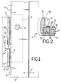
- Figure 1 is a vertical sectional view showing schematically a sliding-type sash in the shut condition; and
- Figure 2 is a vertical sectional view through the hooked bolt of this invention.
- With reference to the above-detailed drawing views, the
numeral 1 designates the vertical upright of the stationary part of a sash of a kind fabricated, for example, from conventional metal sectional members. - That upright has its
wall 2, shown in section, with asurface 3 intended to face mate with the surface 4 of the vertical upright 5 of the moving part of the sash, with the latter in its shut condition. - The sliding movement of the moving part is indicated by a double-headed arrow F.
- Conventionally mounted inside a purposely provided housing in the sectional member which forms the upright 5 is a
lock 6 whose outline is shown by dash lines in the drawing. - That lock is provided with a bolt, generally indicated at 7, which is driven in a conventional way by the lock mechanism on application of a rotary impulse to the square pin 8 by means of a handle or knob, not shown.
- The bolt 7 engages with the
wall 2 of the fixed upright 1 by passing in an angularly downward movement as viewed in Figure 1 through anopening 9. - The engagement of the bolt 7 with the
wall 2 takes place between thesurface 10, facing the lock, of the hook-shaped terminatingportion 11 and thesurface 12 of thewall 2. - With specific reference to Figure 2, it may be seen that the hook-
shaped portion 11 of the bolt 7 is carried on a firsttubular element 13 fitting slidably over a second, rod-like element 14 which is connected to the lock actuating mechanism, not shown because quite conventional. - That
second element 14 has an inside threaded through-goinghole 15 in which asetscrew dowel 16 engages which has adrive head 17 and apressure end 18 adapted to push down on theinner surface 19 of thetubular element 13. - The latter is formed with a
slot 20 which extends longitudinally in front of thedrive head 17 of thesetscrew dowel 16 whose length is selected to allow itsdrive head 17 to lie within theslot 20. - The cross-sectional shape of the
tubular element 13 and the corresponding one of the solid rod-like element 14 are preferably quadrangular. - It may be appreciated from the foregoing that, by backing out the
setscrew dowel 16 from thehole 15 with a suitable tool (screwdriver) to be passed through thelongitudinal slot 20, the hookedportion 11 of the bolt can be made slidable over theelement 14 to an appropriate position to produce a correct engagement of thesurface 10 with theledge 12, thereby on shutting the sash, the surface 4 of the moving upright 5 can be brought to a close fit against thesurface 3 of the stationary upright 1. - The dash-and-dot outlines shown in Figures 1 and 2 are the position attainable by the
hook 11 in consequence of its adjustment lengthwise of theelement 14. - Once the best setting is found in relation to the thickness of the
wall 2 of the fixed upright 1, thesetscrew dowel 16 is tightened down in its threaded hole, and the pressure exerted by theend 18 on thesurface 19 enables the setting to be retained. - Furthermore, the lay of the
setscrew 16 with itsdrive head 17 inside theslot 20 ensures that, should the frictional engagement fail of thepressure end 18 with thesurface 19, as may be overcome in the instance of sliding sashes, theelement 14 cannot slip axially off thetubular element 13. This constitutes a safeguard against possible attempts at forcing the sash open.
Claims (5)
Priority Applications (1)
| Application Number | Priority Date | Filing Date | Title |
|---|---|---|---|
| AT89107359T ATE92575T1 (en) | 1988-12-20 | 1989-04-24 | ADJUSTABLE LATCH FOR LEAF LOCKS OF SLIDING DOORS OR WINDOWS OR THE LIKE. |
Applications Claiming Priority (2)
| Application Number | Priority Date | Filing Date | Title |
|---|---|---|---|
| IT2301988 | 1988-12-20 | ||
| IT8823019A IT1227698B (en) | 1988-12-20 | 1988-12-20 | ADJUSTABLE BOLT FOR SLIDING DOOR LOCKS SUCH AS DOORS AND WINDOWS |
Publications (2)
| Publication Number | Publication Date |
|---|---|
| EP0374351A1 true EP0374351A1 (en) | 1990-06-27 |
| EP0374351B1 EP0374351B1 (en) | 1993-08-04 |
Family
ID=11202962
Family Applications (1)
| Application Number | Title | Priority Date | Filing Date |
|---|---|---|---|
| EP89107359A Expired - Lifetime EP0374351B1 (en) | 1988-12-20 | 1989-04-24 | An adjustable bolt for sash locks such as on sliding door and window sashes |
Country Status (6)
| Country | Link |
|---|---|
| EP (1) | EP0374351B1 (en) |
| AT (1) | ATE92575T1 (en) |
| DE (1) | DE68908124D1 (en) |
| ES (1) | ES2018772T3 (en) |
| GR (1) | GR900300174T1 (en) |
| IT (1) | IT1227698B (en) |
Cited By (5)
| Publication number | Priority date | Publication date | Assignee | Title |
|---|---|---|---|---|
| GB2298450A (en) * | 1995-03-03 | 1996-09-04 | Securistyle Ltd | Adjustable length shoot bolt |
| EP1130200A3 (en) * | 2000-03-01 | 2003-02-12 | Abus Aug. Bremicker Söhne Kg | Locking device |
| US6684669B1 (en) * | 1997-02-19 | 2004-02-03 | Joseph Talpe | Door fastener device |
| US20230323706A1 (en) * | 2022-03-24 | 2023-10-12 | Fakro PP Sp. z o. o. | Box construction lock |
| EP4335997A1 (en) * | 2022-09-12 | 2024-03-13 | Steinbach & Vollmann GmbH | Closing assembly for a door and door with closing assembly |
Citations (2)
| Publication number | Priority date | Publication date | Assignee | Title |
|---|---|---|---|---|
| GB1396876A (en) * | 1971-11-18 | 1975-06-11 | Marsland Co Ltd | Bolt mechanism for sliding doors and other sliding panels |
| US4209194A (en) * | 1978-06-05 | 1980-06-24 | Hartwell Corporation | Keeper for rotary latches |
-
1988
- 1988-12-20 IT IT8823019A patent/IT1227698B/en active
-
1989
- 1989-04-24 AT AT89107359T patent/ATE92575T1/en active
- 1989-04-24 DE DE8989107359T patent/DE68908124D1/en not_active Expired - Lifetime
- 1989-04-24 EP EP89107359A patent/EP0374351B1/en not_active Expired - Lifetime
- 1989-04-24 ES ES89107359T patent/ES2018772T3/en not_active Expired - Lifetime
-
1991
- 1991-09-27 GR GR90300174T patent/GR900300174T1/en unknown
Patent Citations (2)
| Publication number | Priority date | Publication date | Assignee | Title |
|---|---|---|---|---|
| GB1396876A (en) * | 1971-11-18 | 1975-06-11 | Marsland Co Ltd | Bolt mechanism for sliding doors and other sliding panels |
| US4209194A (en) * | 1978-06-05 | 1980-06-24 | Hartwell Corporation | Keeper for rotary latches |
Cited By (7)
| Publication number | Priority date | Publication date | Assignee | Title |
|---|---|---|---|---|
| GB2298450A (en) * | 1995-03-03 | 1996-09-04 | Securistyle Ltd | Adjustable length shoot bolt |
| GB2298450B (en) * | 1995-03-03 | 1998-04-29 | Securistyle Ltd | A shoot bolt |
| US6684669B1 (en) * | 1997-02-19 | 2004-02-03 | Joseph Talpe | Door fastener device |
| EP1130200A3 (en) * | 2000-03-01 | 2003-02-12 | Abus Aug. Bremicker Söhne Kg | Locking device |
| US20230323706A1 (en) * | 2022-03-24 | 2023-10-12 | Fakro PP Sp. z o. o. | Box construction lock |
| US12559983B2 (en) * | 2022-03-24 | 2026-02-24 | Fakro PP Sp. z o. o. | Box construction lock |
| EP4335997A1 (en) * | 2022-09-12 | 2024-03-13 | Steinbach & Vollmann GmbH | Closing assembly for a door and door with closing assembly |
Also Published As
| Publication number | Publication date |
|---|---|
| IT1227698B (en) | 1991-04-23 |
| ES2018772T3 (en) | 1998-06-01 |
| GR900300174T1 (en) | 1991-09-27 |
| ES2018772A4 (en) | 1991-05-16 |
| IT8823019A0 (en) | 1988-12-20 |
| DE68908124D1 (en) | 1993-09-09 |
| EP0374351B1 (en) | 1993-08-04 |
| ATE92575T1 (en) | 1993-08-15 |
Similar Documents
| Publication | Publication Date | Title |
|---|---|---|
| CA1210790A (en) | Fastener for sliding doors or windows | |
| WO1996025576A1 (en) | Lock for sliding door | |
| US7452014B2 (en) | Multi-point sash lock system for casement window | |
| US5489128A (en) | Lockset having adjustable backset | |
| US4828301A (en) | Locking fitting, in particular for sliding casement | |
| EP0374351A1 (en) | An adjustable bolt for sash locks such as on sliding door and window sashes | |
| US4968072A (en) | Bolt lock | |
| EP0389448B1 (en) | Bolt mechanism for sliding doors, windows and related items | |
| US4662666A (en) | Door-bolt set | |
| US5141272A (en) | Door and window latch | |
| KR910005295B1 (en) | Locking fitting in particular for the sliding leaf | |
| EP3511497A1 (en) | Connecting rod fitting for a building closure element, corresponding building closure element and method for operating a connecting rod fitting and method for mounting a connecting rod fitting | |
| EP1723300B1 (en) | Locking device with rotating or tilting bolts and bolt adjusting device | |
| US3492038A (en) | Double-acting door pull lock | |
| US6598910B2 (en) | Friction joint and fastener incorporating same | |
| CS271304B2 (en) | Fittings for windows,doors etc. | |
| US20040012208A1 (en) | Externally adjustable latch | |
| GB2211882A (en) | Improvements in or relating to fasteners | |
| US5556142A (en) | Rotary hook tension-shear latch | |
| US4406488A (en) | Quick release door lock | |
| GB2363625A (en) | Shoot bolt mechanism | |
| EP0515317A1 (en) | Door and window handle support and relative fixing insert | |
| GB2076455A (en) | Lockable window fastener | |
| GB2187784A (en) | Fastener | |
| GB2191242A (en) | Window fastener |
Legal Events
| Date | Code | Title | Description |
|---|---|---|---|
| PUAI | Public reference made under article 153(3) epc to a published international application that has entered the european phase |
Free format text: ORIGINAL CODE: 0009012 |
|
| AK | Designated contracting states |
Kind code of ref document: A1 Designated state(s): AT BE CH DE ES FR GB GR IT LI LU NL SE |
|
| 17P | Request for examination filed |
Effective date: 19900606 |
|
| EL | Fr: translation of claims filed | ||
| 17Q | First examination report despatched |
Effective date: 19920117 |
|
| GRAA | (expected) grant |
Free format text: ORIGINAL CODE: 0009210 |
|
| AK | Designated contracting states |
Kind code of ref document: B1 Designated state(s): AT BE CH DE ES FR GB GR IT LI LU NL SE |
|
| PG25 | Lapsed in a contracting state [announced via postgrant information from national office to epo] |
Ref country code: SE Effective date: 19930804 Ref country code: NL Effective date: 19930804 Ref country code: LI Effective date: 19930804 Ref country code: DE Effective date: 19930804 Ref country code: CH Effective date: 19930804 Ref country code: BE Effective date: 19930804 Ref country code: AT Effective date: 19930804 |
|
| REF | Corresponds to: |
Ref document number: 92575 Country of ref document: AT Date of ref document: 19930815 Kind code of ref document: T |
|
| REF | Corresponds to: |
Ref document number: 68908124 Country of ref document: DE Date of ref document: 19930909 |
|
| ET | Fr: translation filed | ||
| ITF | It: translation for a ep patent filed | ||
| REG | Reference to a national code |
Ref country code: ES Ref legal event code: BA2A Ref document number: 2018772 Country of ref document: ES Kind code of ref document: A4 |
|
| REG | Reference to a national code |
Ref country code: CH Ref legal event code: PL |
|
| NLV1 | Nl: lapsed or annulled due to failure to fulfill the requirements of art. 29p and 29m of the patents act | ||
| REG | Reference to a national code |
Ref country code: GR Ref legal event code: FG4A Free format text: 3009572 |
|
| PG25 | Lapsed in a contracting state [announced via postgrant information from national office to epo] |
Ref country code: GB Effective date: 19940424 |
|
| PG25 | Lapsed in a contracting state [announced via postgrant information from national office to epo] |
Ref country code: LU Free format text: LAPSE BECAUSE OF NON-PAYMENT OF DUE FEES Effective date: 19940430 |
|
| PLBE | No opposition filed within time limit |
Free format text: ORIGINAL CODE: 0009261 |
|
| STAA | Information on the status of an ep patent application or granted ep patent |
Free format text: STATUS: NO OPPOSITION FILED WITHIN TIME LIMIT |
|
| 26N | No opposition filed | ||
| GBPC | Gb: european patent ceased through non-payment of renewal fee |
Effective date: 19940424 |
|
| REG | Reference to a national code |
Ref country code: ES Ref legal event code: FA2A Effective date: 19970325 |
|
| REG | Reference to a national code |
Ref country code: ES Ref legal event code: FG2A Ref document number: 2018772 Country of ref document: ES Kind code of ref document: T3 |
|
| PGFP | Annual fee paid to national office [announced via postgrant information from national office to epo] |
Ref country code: GR Payment date: 20020409 Year of fee payment: 14 Ref country code: ES Payment date: 20020409 Year of fee payment: 14 |
|
| PGFP | Annual fee paid to national office [announced via postgrant information from national office to epo] |
Ref country code: FR Payment date: 20020430 Year of fee payment: 14 |
|
| PG25 | Lapsed in a contracting state [announced via postgrant information from national office to epo] |
Ref country code: ES Free format text: LAPSE BECAUSE OF NON-PAYMENT OF DUE FEES Effective date: 20030425 |
|
| PG25 | Lapsed in a contracting state [announced via postgrant information from national office to epo] |
Ref country code: GR Free format text: LAPSE BECAUSE OF NON-PAYMENT OF DUE FEES Effective date: 20031104 |
|
| PG25 | Lapsed in a contracting state [announced via postgrant information from national office to epo] |
Ref country code: FR Free format text: LAPSE BECAUSE OF NON-PAYMENT OF DUE FEES Effective date: 20031231 |
|
| REG | Reference to a national code |
Ref country code: FR Ref legal event code: ST |
|
| REG | Reference to a national code |
Ref country code: ES Ref legal event code: FD2A Effective date: 20030425 |
|
| PG25 | Lapsed in a contracting state [announced via postgrant information from national office to epo] |
Ref country code: IT Free format text: LAPSE BECAUSE OF NON-PAYMENT OF DUE FEES;WARNING: LAPSES OF ITALIAN PATENTS WITH EFFECTIVE DATE BEFORE 2007 MAY HAVE OCCURRED AT ANY TIME BEFORE 2007. THE CORRECT EFFECTIVE DATE MAY BE DIFFERENT FROM THE ONE RECORDED. Effective date: 20050424 |