EP0375220A1 - Gas component extraction - Google Patents
Gas component extraction Download PDFInfo
- Publication number
- EP0375220A1 EP0375220A1 EP89312816A EP89312816A EP0375220A1 EP 0375220 A1 EP0375220 A1 EP 0375220A1 EP 89312816 A EP89312816 A EP 89312816A EP 89312816 A EP89312816 A EP 89312816A EP 0375220 A1 EP0375220 A1 EP 0375220A1
- Authority
- EP
- European Patent Office
- Prior art keywords
- beds
- product gas
- bed
- adsorption
- pressure
- Prior art date
- Legal status (The legal status is an assumption and is not a legal conclusion. Google has not performed a legal analysis and makes no representation as to the accuracy of the status listed.)
- Granted
Links
Images

Classifications
-
- B—PERFORMING OPERATIONS; TRANSPORTING
- B01—PHYSICAL OR CHEMICAL PROCESSES OR APPARATUS IN GENERAL
- B01D—SEPARATION
- B01D53/00—Separation of gases or vapours; Recovering vapours of volatile solvents from gases; Chemical or biological purification of waste gases, e.g. engine exhaust gases, smoke, fumes, flue gases, aerosols
- B01D53/02—Separation of gases or vapours; Recovering vapours of volatile solvents from gases; Chemical or biological purification of waste gases, e.g. engine exhaust gases, smoke, fumes, flue gases, aerosols by adsorption, e.g. preparative gas chromatography
- B01D53/04—Separation of gases or vapours; Recovering vapours of volatile solvents from gases; Chemical or biological purification of waste gases, e.g. engine exhaust gases, smoke, fumes, flue gases, aerosols by adsorption, e.g. preparative gas chromatography with stationary adsorbents
- B01D53/0454—Controlling adsorption
-
- B—PERFORMING OPERATIONS; TRANSPORTING
- B01—PHYSICAL OR CHEMICAL PROCESSES OR APPARATUS IN GENERAL
- B01D—SEPARATION
- B01D2256/00—Main component in the product gas stream after treatment
- B01D2256/12—Oxygen
-
- B—PERFORMING OPERATIONS; TRANSPORTING
- B01—PHYSICAL OR CHEMICAL PROCESSES OR APPARATUS IN GENERAL
- B01D—SEPARATION
- B01D2257/00—Components to be removed
- B01D2257/10—Single element gases other than halogens
- B01D2257/102—Nitrogen
-
- B—PERFORMING OPERATIONS; TRANSPORTING
- B01—PHYSICAL OR CHEMICAL PROCESSES OR APPARATUS IN GENERAL
- B01D—SEPARATION
- B01D2259/00—Type of treatment
- B01D2259/40—Further details for adsorption processes and devices
- B01D2259/40007—Controlling pressure or temperature swing adsorption
- B01D2259/40009—Controlling pressure or temperature swing adsorption using sensors or gas analysers
-
- B—PERFORMING OPERATIONS; TRANSPORTING
- B01—PHYSICAL OR CHEMICAL PROCESSES OR APPARATUS IN GENERAL
- B01D—SEPARATION
- B01D2259/00—Type of treatment
- B01D2259/40—Further details for adsorption processes and devices
- B01D2259/402—Further details for adsorption processes and devices using two beds
-
- B—PERFORMING OPERATIONS; TRANSPORTING
- B01—PHYSICAL OR CHEMICAL PROCESSES OR APPARATUS IN GENERAL
- B01D—SEPARATION
- B01D2259/00—Type of treatment
- B01D2259/45—Gas separation or purification devices adapted for specific applications
- B01D2259/4566—Gas separation or purification devices adapted for specific applications for use in transportation means
- B01D2259/4575—Gas separation or purification devices adapted for specific applications for use in transportation means in aeroplanes or space ships
-
- B—PERFORMING OPERATIONS; TRANSPORTING
- B01—PHYSICAL OR CHEMICAL PROCESSES OR APPARATUS IN GENERAL
- B01D—SEPARATION
- B01D53/00—Separation of gases or vapours; Recovering vapours of volatile solvents from gases; Chemical or biological purification of waste gases, e.g. engine exhaust gases, smoke, fumes, flue gases, aerosols
- B01D53/02—Separation of gases or vapours; Recovering vapours of volatile solvents from gases; Chemical or biological purification of waste gases, e.g. engine exhaust gases, smoke, fumes, flue gases, aerosols by adsorption, e.g. preparative gas chromatography
- B01D53/04—Separation of gases or vapours; Recovering vapours of volatile solvents from gases; Chemical or biological purification of waste gases, e.g. engine exhaust gases, smoke, fumes, flue gases, aerosols by adsorption, e.g. preparative gas chromatography with stationary adsorbents
- B01D53/047—Pressure swing adsorption
Definitions
- the present invention concerns apparatus for extracting one component from a gas mixture with sorption beds that adsorb the component and are regenerated after adsorbing the component.
- the invention relates to alternately operating one sorption bed to adsorb the component and produce a product gas from which the component is extracted while regenerating a second sorption bed.
- the operation and regeneration intervals of the sorption beds are controlled in the invention to optimize the product gas output for a gas mixture supply.
- the apparatus may be advantageously employed to produce an oxygen-enriched breathable gas from air for the crew of an aircraft.
- sorption techniques have been employed to produce a breathable gas mixture from ambient air. Because air at the altitudes of concern contains insufficient oxygen for crew members, sorption beds that preferentially adsorb nitrogen are employed to produce the breathable mixture. Ambient air that is compressed by an aircraft engine or an auxiliary compressor is supplied to the sorption apparatus where a sorption material, typically a molecular sieve, preferentially adsorbs nitrogen while allowing oxygen and the other components of air, principally argon, to pass through.
- a sorption material typically a molecular sieve
- Molecular sieve sorption beds can readily produce a product gas containing more than 94% oxygen.
- Appropriate molecular sieve materials are commercially available, such as type 5A produced by Union Carbide Corporation and Bayer A.G. and type 13X, also available from Union Carbide Corporation. These molecular sieves are well known in pressure swing adsorption technology.
- a sorption bed is effective in adsorbing a component of a gas when a gas mixture is supplied under pressure to the bed.
- the bed becomes filled with the adsorbed component and adsorption performance declines.
- a sorption bed is regenerated, i.e., its adsorptive efficiency is restored, by releasing the gas pressure and flushing the bed, usually in a reverse flow direction, with some of the product gas produced by another bed.
- the reverse flow of oxygen encourages desorption of adsorbed nitrogen.
- the regeneration process thus includes a depressurizing step and a purging step.
- the adsorption characteristics of a sorption bed material i.e., the effectiveness of the adsorption over time, depend upon the pressure and temperature of the gas mixture supplied.
- the desorption or regeneration characteristics of a sorption bed depend upon the pressure within the bed. For a particular sorption bed material, those adsorption and regeneration characteristics can be determined by laboratory measurements.
- the inlet gas mixture is air, pressurized by and bled from one of the aircraft engines.
- This pressurized air is further conditioned, i.e., its temperature is reduced and aerosols (small liquid particles) and particulates filtered out, for use in crew-occupied spaces on an aircraft or in the breathable gas generation system described herein.
- the present invention provides for a relatively small and lightweight apparatus for extracting one component from an inlet gas mixture to produce a product gas mixture.
- the invention also provides for an apparatus for maximizing the efficiency of a sorption apparatus so that an optimum quantity of a product gas can be derived from a limited supply of an inlet gas, over a wide range of inlet gas conditions.
- the invention further provides for an apparatus for extracting a component from a gas mixture employing sorption beds wherein the intervals of adsorption and purging during regeneration of the beds are determined and controlled based on the conditions of the inlet gas, ambient pressure, and the adsorption and desorption characteristics of the sorption bed material in order to optimize product gas production.
- the invention also provides for repeated sampling of the conditions of the inlet gas, and of the ambient pressure, correspondingly determining and changing the intervals of adsorption and purging to optimize the production of a product gas to meet or exceed an established quality standard.
- At least two sorption beds are provided, each of which includes an inlet and outlet for the flow of gas therethrough and a respective inlet and vent valve connected at the inlet of each bed.
- Sensors are provided for measuring ambient pressure and the temperature and pressure of the inlet gas supplied to the inlet valves.
- the apparatus includes a control unit that responds to the measured ambient pressure and temperature and pressure of the inlet gas and that, from knowledge of the characteristics of the sorption bed material, determines adsorption and purging intervals for the bed that optimize product gas output.
- the control unit actuates the inlet and vent valves so that one bed is operational and produces a desired product gas while the other sorption bed is being regenerated at relatively low pressure with a backward flow of product gas in a variable quantity determined by the control unit.
- the control unit comprises a microprocessor that repetitively samples the inlet gas conditions and the ambient pressure, determines optimum current adsorption and purge intervals, and implements the currently determined intervals.
- the present invention provides for an apparatus for extracting a component from a gaseous mixture
- an apparatus for extracting a component from a gaseous mixture comprising: (a) first and second sorption beds, each bed having an inlet for admitting gas and an outlet for discharging gas, said beds for, in an operating condition, adsorbing a component from an inlet gas mixture and supplying as a product gas the mixture from which the component has been adsorbed, and for, in a regenerating condition, desorbing the adsorbed component; (b) an inlet conduit for supplying the inlet gas mixture to said inlets of said first and second beds; (c) first and second inlet valves connected between said inlet conduit and said inlets of said first and second beds, respectively, for selectively admitting the inlet gas mixture to said first and second beds; (d) first and second vent valves in fluid communication with said first and second beds, respectively, for venting said first and second beds to the ambient; (e) means for admitting product gas from one bed in an operating condition to
- the present invention also provides for an apparatus for supplying a breathable gas mixture to aircraft crew members from compressed air comprising: (a) first and second sorption beds, each bed having an inlet for admitting air and an outlet for discharging air, respectively, said beds for, in an operating condition, adsorbing nitrogen from air and supplying an oxygen-enriched mixture as a product gas, and for, in a regenerating condition, desorbing adsorbed nitrogen from said beds; (b) an inlet conduit for supplying the inlet gas mixture to said inlets of said first and second beds; (c) first and second inlet valves connected between said inlet conduit and said inlets of said first and second beds, respectively, for selectively admitting air to said first and second beds; (d) first and second vent valves in fluid communication with said first and second beds, respectively, for venting said first and second beds; (e) means for admitting product gas from one bed in an operating condition to the other bed in a regenerating condition to purge said other bed; (f) first and second sensors in fluid communication with
- the present invention further provides for a method of optimizing the production of a product gas mixture in a pressure swing apparatus including two regenerable sorbent beds from an inlet gas mixture from which the sorbent beds extract a component to produce the product gas mixture comprising: (a) extracting a component from a pressurized inlet gas mixture by passing it through a first sorbent bed during an adsorption interval thereby producing a product gas mixture; (b) regenerating a second sorbent bed during the adsorption interval of the first sorbent bed including passing a quantity of the product gas from the first sorbent bed through the second sorbent bed in a reverse direction during a purging interval while the second sorbent bed is vented to the ambient; (c) alternating the first and second beds between adsorption and regeneration operations; (d) sensing the ambient pressure and the temperature and pressure of the pressurized inlet gas mixture; (e) determining from the sensed ambient pressure and the temperature and pressure of the pressurized inlet gas mixture and from the sorption characteristics of
- That apparatus includes an inlet conduit 1 through which a pressurized inlet gas mixture is supplied to the apparatus.
- That mixture may be conditioned bleed air from an aircraft engine.
- the bleed air may be conditioned by drying, filtering, and/or other steps before being supplied to conduit 1.
- the pressure and temperature of the gas applied through conduit 1 are respectively sensed by a pressure sensor 2 and a temperature sensor 3.
- Those sensors are of conventional construction and produce analog electrical signals as indications of the gas mixture pressure and temperature.
- Pressure sensor 2 is a conventional strain gauge type semiconductor pressure sensor.
- Temperature sensor 3 may be a resistance temperature detector (RTD).
- the conduit 1 divides into two identical legs.
- an inlet valve 4 preferably a pneumatically piloted solenoid actuated diaphragm valve, controls the flow of the inlet gas to an inlet 5 of a sorption bed 6.
- a vent valve 7 is also connected to the inlet 5 of sorption bed 6 for venting the bed during the regeneration process.
- Valve 7 is also preferably a pneumatically piloted, solenoid actuated diaphragm valve.
- valve 4 is open and valve 7 is closed.
- Inlet gas flows into bed 6 through inlet 5 and product gas flows out through an outlet 8.
- Outlet 8 is connected through a check valve 9 to a reserve tank 12 containing a volume of the product gas.
- Check valve 9 allows gas to flow from bed 6 to tank 12, but prevents backflows into bed 6 through outlet 8.
- Bypass 10 allows a restricted flow of product gas into and out of sorption bed 6 through outlet 8 and is used in the regeneration of bed 6 as described below.
- the sorption bed arrangement in the lower half of Figure 1 is identical to that in the upper half. Like elements are identified by similar reference numerals increased by ten.
- An inlet valve 14 selectively supplies the inlet gas mixture to inlet 15 of sorption bed 16.
- a vent valve 17 connected to inlet 15 is employed in the regeneration of bed 16.
- Bed 16 includes an outlet 18 connected to a check valve 19.
- the product gas generated by sorption bed 16 is supplied through check valve 19 to tank 12.
- a bypass 20 containing a flow restricting element is pneumatically connected in parallel with check valve 19 to allow a backflow of product gas to sorption bed 16 while that bed is being regenerated.
- Tank 12 functions as a reservoir and also smoothes surges in the pressure of the product gas that may be produced, for example, when a bed is taken out of adsorption service to be regenerated.
- Tank 12 includes an outlet conduit for transporting the product gas to other devices, such as regulators and/or breathing masks for aircraft crew members.
- pressure sensor 21 for measuring the ambient pressure is provided.
- pressure sensor 21 is preferably a conventional strain gauge type semiconductor pressure sensor.
- the apparatus of Figure 1 includes a control unit 22 that is in electrical communication with sensors 2, 3, and 21 as well as with the solenoids that actuate valves 4, 7, 14, and 17. (The dashed lines of Figure 1 indicate electrical connections while the solid lines indicate fluid connections.)
- Control unit 22 receives the electrical signals from the sensors and employs them in calculations for controlling the adsorption and regeneration operations of the sorption bed apparatus. Control unit 22 responds by actuating valves 4, 7, 14, and 17, opening or closing them in the course of a gas component extraction process.
- Beds 6 and 16 operate together in a cycle of variable duration.
- adsorbing a gas component and producing product gas During one part of the cycle bed 6 is operational, adsorbing a gas component and producing product gas.
- a different part of the cycle bed 16 is adsorbing and producing product gas. That is, one bed is in service during part of the cycle and during that part of the cycle the other bed is off-line.
- a bed is offline, it is regenerated by being depressurized, i.e., exposed to ambient pressure, and product gas is allowed to purge it by flowing through the bed in a backward direction, i.e., into the outlet and out through an opened vent valve.
- the backward flow of product gas aids the desorption by the bed of the adsorbed gas component to complete the regeneration process.
- Regeneration of an offline bed may begin immediately after a bed is taken out of service or may be delayed for an interval after the inlet valve to the bed has been closed.
- the duration of the cycle, the variable adsorption intervals of the beds, the variable regeneration intervals, and the timings of the intervals are determined and implemented by control unit 22 in response to sensed data and stored adsorption and regeneration characteristic data.
- bed 6 may be adsorbing.
- Valve 4 is open and valve 7 is closed so that an inlet gas mixture is supplied to bed 6 where one component of the gas mixture is being adsorbed.
- the product gas flows through check valve 9 toward tank 12.
- valve 4 is closed.
- valve 7 is opened to vent, i.e., depressurize bed 6.
- Bed 6 reaches a pressure at or near that of the ambient. That pressure may be below atmospheric when valve 7 is vented at a high altitude.
- bed 16 is put into operation by the opening of valve 14 and begins adsorbing a component of the inlet gas mixture.
- the product gas bed 16 produces flows to tank 12 through check valve 19. After depressurization of bed 6, some of the product gas flows through bypass 10 and through bed 6, in a direction opposite the flow during adsorption, and out open valve 7. That reverse flow of purging gas occurs because of the high pressure of the product gas compared to the ambient beyond open valve 7.
- the flowing product gas purges adsorbed gas from bed 6.
- the regeneration process includes a depressurization step followed by a purge step.
- valve 7 is closed. If bed 16 continues to produce product gas before bed 6 is brought back into operation, that product gas pressurizes bed 6 through bypass 10. Eventually, bed 16 is taken out of adsorption service for regeneration by the closing of valve 14 and bed 6 is placed back into adsorbing operation by opening valve 4. All of these actions in one cycle are implemented by control unit 22.
- control unit 22 Besides receiving the sensor signals, control unit 22 also stores the characteristics of the sorbent material employed in sorption beds 6 and 16. Control unit 22 includes a calculational capability for predicting the performance of the sorbent beds while adsorbing a component of a gas mixture under pressure and for predicting the degree of regeneration of the beds when depressurized and purged. These calculations are made based upon the information provided to control unit 22 by sensors 2, 3, and 21 and the stored sorption bed characteristics. Most preferably, control unit 22 includes a microprocessor and associated programmable read-only memories.
- Microprocessor 41 may be a conventional, commercially available microprocessor such as an Intel 8097. That type of microprocessor is particularly advantageous because it includes an eight channel multiplexer and a successive approximation analog-to-digital converter so that the multiple analog signals provided by the various sensors are easily converted to a digital format. In addition, microprocessor 41 linearizes the response of the sensors.
- the clock rate of the microprocessor is controlled by an external frequency control, shown as a crystal 43, for controlling the frequency of the basic oscillator within the microprocessor.
- Memory 45 is a programmable read-only memory (EPROM) for storing the program executed by microprocessor 41.
- EPROM programmable read-only memory
- the adsorption and regeneration characteristics of the sorption bed material as a function of ambient pressure and inlet gas mixture pressure and temperature are stored in memory 45 for use in the valve control calculations carried out by microprocessor 41.
- Memory 47 is a static random access memory including an electrically erasable programmable read-only memory (RAM/EEPROM) in which calibration data for the sensors and fault code information are stored. Memory 47 also provides a scratch pad for computations.
- valves 4, 7, 14, and 17 are actuated to carry out the desired product gas production process.
- These valves typically employ solenoids that admit air to a diaphragm to actuate the valve.
- output signals generated by microprocessor 41 are passed to buffer amplifiers 49, 50, 51, and 52, respectively, and thereafter to solenoid coils 53, 54, 55, and 56, respectively.
- solenoids admit pressurized air to actuate valves 4, 7, 14, and 17 of the preferred construction.
- microprocessor 41 includes a built-in test program for determining the proper operation of the electronics each time power is applied to the microprocessor and for periodically monitoring the status of the sensors. For example, when a sensor produces a signal that is outside a reasonable range, the sensor is assumed to have failed. The microprocessor then ignores the sensor signal and substitutes a worst case, extreme value as the sensor signal. This response ensures continued production of product gas, but at a reduced effi ciency. If a catastrophic failure is detected, the program defaults to a predetermined status for the valves. In either case, a status signal is produced and supplied to an indicator 57 as a warning of the existence of a failure and, possibly, its severity.
- Warning 57 may be a light that is illuminated upon the occurrence of a failure.
- a fault code is stored in a non-volatile memory for subsequent identification of the source of the failure.
- the fault code discloses the abnormality that has occurred so that appropriate maintenance procedures can be carried out.
- a catastrophic failure provides an immediate warning so that action can be taken.
- the needed action may be switching to a backup supply of breathable air or a descent to an altitude where the oxygen content of the ambient air is acceptable.
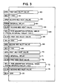
- FIG. 3 is a flow diagram illustrating a valve operating sequence consisting of steps 60 through 75.
- An adsorption process for a first bed begins at step 60 where the inlet valve is open and ends at step 66 where that inlet valve is closed.
- the first bed is continuing to adsorb a gas component. That adsorption continues until the expiration of the delay interval of step 65, namely, the total adsorption interval less the sum of the purge interval and the initial delay of step 61.
- a further delay 200 takes place between the adsorption operations of the first and second beds at step 67.
- Certain of the delays are numbered in Figure 3 for identification, but those identifying numbers are no indication of the duration of the delays.
- all of the delays are variable in duration and the durations are determined by control unit 22 as hereinafter described to optimize performance.
- step 67 After the completion of a variable length delay 200 in step 67, the sequence of steps 60-66 are repeated as steps 68-74, but with the first and second beds interchanged. Thereafter, at step 75 after a delay corresponding to the delay of step 67, the sequence returns to step 60 and is repeated.
- control unit 22 can make adjustments in the timing of the valve sequencing to ensure optimum production of product gas in the adsorption/regeneration cycle.
- Other valving sequences can be employed. For example, while Figure 3 shows sequential adsorption intervals for the separate beds, in some situations the adsorption intervals could overlap in time. In that case, for example, delay 200 in the Figure 3 flow chart would be negative.
- valves under the control of unit 22 ensures that the optimum quantity of product gas is generated when the inlet gas is subject to relatively wide swings in temperature and pressure and when its quantity is limited.
- the nominal average quantity of compressed air available as a bleed gas from an engine may be limited to 0.68 kg/min (1.5 lbs/min). It is therefore of substantial importance that an optimum quantity of a breathable gas mixture be produced from a limited quantity, highly variable source. That result is achieved in the invention by controlling and changing the adsorption and purge intervals in response to changes in ambient pressure and in the pressure and temperature of the inlet gas mixture.
- difversible tests can be applied in determining the adsorption and purging intervals depending upon the mode of operation.
- the product gas flowing out of the sorption beds is supplied directly to the crew members without dilution.
- the product gas must contain at least a specified oxygen content and be provided at a specified minimum flow rate. That oxygen content is expressed in terms of a partial pressure of oxygen which, for example, may be 200 mm Hg and a typical minimum flow rate may be 100 standard liters per minute (slpm).
- time intervals t0, t1, t2, t4, and t5 are repeatedly calculated by the control unit in response to repeated measurements of the ambient pressure and of the conditions of the inlet gas.
- Time interval t3 is also employed in determining the appropriate adsorption and purging intervals.
- t0 is the minimum adsorption interval.
- the inlet gas In each cycle of the apparatus a certain amount of the inlet gas is wasted, i.e., none of it becomes product gas.
- a shorter cycle time means more frequent valve operation, including venting, and more lost, i.e., unused, inlet gas. That is, more gas is consumed, both in producing product gas and in waste, as the cycle time is shortened.
- the quantity per unit time of inlet gas is limited, at a certain adsorption interval, t0, all of the inlet gas that is allocated to the extraction apparatus is consumed. Therefore, the adsorption interval, i.e., the duration of adsorption service by each bed in one cycle, cannot be shorter than t0.
- t1 is the purging interval required to purge a bed with a quantity of product gas that exceeds the minimum purging quantity required for efficient regeneration by a predetermined excess amount, e.g., 20 percent, plus the time needed for operating the valves. t1 fixes the minimum time interval for adsorption by one bed while another bed is being purged with the specified excess over the minimum quantity of product gas necessary for efficient regeneration. Regeneration efficiency depends upon the pressure swing of the beds, here the difference between the inlet gas pressure and the ambient pressure, and the quantity of purging gas that flows. The purging gas flow rate is a function of inlet pressure. Thus, the purging interval determines the quantity of purging gas that flows.
- Control unit 22 can calculate the purging interval, taking into account the required quantity of purge gas, from the stored bed characteristics and sensed pressures, that restores a bed to a specified degree of adsorption performance.
- the term efficient regeneration refers to purging that is just sufficient to restore a bed to that specified degree of adsorption performance.
- t2 is the adsorption interval that will produce a sufficient quantity of product gas to purge the offline regenerating bed with a specified excess quantity of product gas, e.g., 1.2 times the minimum quantity of product gas needed for efficient regeneration, and simultaneously produce product gas containing a minimum specified partial pressure of a desired component at a specified minimum flow rate.
- t2 establishes an upper limit for the adsorption interval.
- t3 is the minimum adsorption interval allowable.
- the minimum allowable adsorption interval is fixed for a particular apparatus configuration and may be, for example, about 3 seconds. Different values of t3 apply to different apparatus configurations.
- t4 is the interval required to purge a regenerating bed with the minimum quantity of product gas for efficient regeneration plus the time needed for operating the valves. t4 is similar to t1 except that the minimum quantity of product gas for efficient regeneration is assumed in calculating t4, rather than the excess that is assumed in calculating t1.
- t5 is the adsorption interval that will produce a sufficient quantity of product gas to purge the offline regenerating bed with the minimum quantity of product gas necessary for efficient regeneration and simultaneously produce product gas with the minimum specified partial pressure of a desired component at the specified minimum flow rate. t5 establishes an upper limit for adsorption interval.
- Time intervals t0, t1, t2, t4, and t5 are calculated in control unit 22 by retrieving the stored sorbent bed material characteristics which are a function of the ambient pressure and the temperature and pressure of the inlet gas. Those characteristics predict the quantity and quality of the product gas that is produced for various ambient pressures and inlet gas conditions, taking into account the geometry and the size of the particular sorbent beds employed. Those characteristics allow the calculation of the time intervals t0, t1, t2, t4, and t5, taking into account the declining efficiency of the sorbent material as the adsorption process is carried out and the effectiveness of the regeneration process.
- control unit 22 automatically and repetitively determines the adsorption and purge intervals based on each set of calculated values for t0, t1, t2, t4, and t5, and t3 to optimize product gas production.
- t4 and t5 are used at extreme operating conditions (i.e., low inlet gas pressure, high inlet gas temperature, high ambient pressure) where the difficulty in obtaining the required performance is the greatest.
- the choice of the adsorption interval is made based upon the calculated value of t2, the maximum adsorption interval when an extended purge can be carried out during regeneration. That choice is desirable to obtain superior adsorption performance.
- Interval t2 is calculated, as described above, based upon the characteristics of the inlet gas supply to the apparatus for extraction of a component. If that value, t2, is greater than or equal to the maximum of t0, t1, and t3, then an adsorption interval of that length will provide an operational cycle and t2 is chosen as the adsorption interval. That choice means that one bed can adsorb a component from the inlet gas while another bed completes an entire regeneration process including purging with an excess quantity of product gas.
- the purge portion of the regeneration process is set equal to t1 less the valve opening and closing times. If t2 is not greater than or equal to the maximum of t0, t1, and t3, then the control unit establishes as the adsorption interval the maximum of t3, t4, and t5. This selection assures that the adsorption interval at least equals the minimum allowable interval and, if possible, sets the adsorption interval to exceed the purge interval when the minimum quantity of product gas for efficient regeneration is employed in the purge. In this case, the purge interval is set equal to t4 less the valve opening and closing time.
- intervals t0 through t6 are initially calculated.
- Intervals t0, t1, t3, and t4 have the same definitions as the corresponding intervals in the first example.
- Intervals t1 and t4 are calculated in the same way as the corresponding times described above for the first example.
- the time t2 is different from that of the preceding example.
- a required minimum flow rate to the diluting regulator of an assumed minimum quality, e.g., 93% oxygen content, and to the reservoir are specified.
- interval t2 is an adsorption interval that produces the desired flow assuming that an excess volume of product gas is employed in purging regenerating beds.
- 120 percent of the minimum quantity of product gas necessary for efficient regeneration of a bed is employed to purge a regenerating bed.
- the calculated value of t2 is thus the maximum adsorption interval for a single bed while the reservoir is being charged.
- An interval t5 is calculated as the adsorption interval when the required flow rate is provided to the diluting regulators, but without charging the reservoir, assuming that an excess quantity of product gas over that required for efficient regeneration is employed in purging a regenerating sorption bed.
- This interval t5 is the maximum adsorption interval when the reservoir is not being filled.
- An interval t6 is also calculated which is similar to t5, except that the purge step of the regeneration process employs only the minimum needed volume of product gas to purge a regenerating bed efficiently.
- this second example includes the additional option of charging a reservoir
- the determination of an adsorption interval from the intervals t0 through t6 is more complicated than in the first example.
- a sensor for measuring the pressure of the product gas flowing from the beds and another sensor for measuring the pressure of the product gas in the reservoir may be needed. That pressure information is important in the selection of the adsorption and purging intervals. However, since those sensors (which are not shown in Figure 1) measure pressure directly, they do not increase the complexity of the apparatus excessively.
- t2 an adsorption time when the reservoir is being charged and excess purge quantities are employed, is greater than or equal to the maximum of t0, t1, and t3, and the pressure in the reservoir is less than the pressure of the product gas, then t2 is chosen as the adsorption interval. The purge interval is then chosen equal to t1 less the valve switching time. In this mode of operation, the reservoir can be filled. If, on the other hand, t2 is not at least equal to the maximum of t0, t1, and t3, or the pressure of the product gas does not exceed the pressure in the reservoir, a secondary test is applied.
- t5 is greater than or equal to the maximum of t0, t1, and t3, then sufficient product gas can be produced to supply breathing needs, even though there may not be sufficient excess product gas to charge the reservoir.
- the adsorption interval is then established as t5 and the purge interval is established at t1 minus the valve switching time, the same purge interval as in the prior situation of this second example. Both of the foregoing situations assume purging with an excess quantity of product gas. If t5 is not at least equal to the maximum of t0, t1, and t3, then an adsorption interval of t5 will not provide a workable cycle. In that case, to optimize product gas production, only the minimum quantity of product gas is used in the purging step.
- the adsorption interval is thus set equal to the maximum of t0, t4, and t6. As in the first example, this cycling arrangement ensures that the regeneration process takes no more time than the adsorption process. In this third situation, the purge interval is set to t4 less the valve switching time. In this third and default option of the second example, the product gas reservoir cannot be filled.
- the two examples described do not exhaust the methods of applying the invention. However, those examples demonstrate the utilization of the sorption beds with a limited and highly variable supply of the inlet gas mixture to maximize the efficiency of the sorption process and optimize the production of product gas even at extreme air and gas pressures and temperatures. While the two examples have each explained a single determination of an adsorption interval, the calculations and determinations are made repetitively in real time in the apparatus. For example, ambient pressure and the temperature and pressure of the inlet gas mixture may be measured twenty times per minute with corresponding determinations of optimized adsorption and purge intervals. The intervals actually employed are changed, usually at the end of a valve state change, to continually optimize bed efficiency and product gas generation. The two examples have also described apparatus employing two sorption beds that are alternatively operated and regenerated. The invention can also be applied to apparatus including more than two sorption beds.
- the invention responds to changes in ambient pressure and the temperature and pressure of the inlet gas, its product gas production is optimized. That is, for particular capacity beds, the maximum possible quantity of product gas can be produced. Bed capacity need not be chosen to be large enough to handle the maximum expected inlet gas mixture flow. Instead, smaller, lighter beds can be employed to produce quantities of product gas that are comparable to those produced by much larger beds. This result can be achieved because, at large inlet gas mixture flows, the adsorption interval and cycle time are shortened, pressing the beds to perform at their maximum adsorption rates. At lower inlet gas flow rates, the adsorption interval is lengthened. Again, the beds are pressed to maximum performance for the conditions, but with emphasis on longer adsorption intervals rather than on maximum adsorption rates.
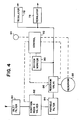
- FIG. 4 shows a block diagram of the invention used in a breathable air supply system for an aircraft crew.
- This system includes two breathing masks (not shown) each of which is fed by a separate breathing regulator 78.
- Breathing regulators 78 supply product gas directly to the masks or mix the product gas with a diluting gas depending upon the selected operational mode.
- a filter 80 is employed to remove aerosols and particulates from air, in this case conditioned air bled from the engine of the aircraft.
- the filtered gas mixture is supplied to a concentrator 82, which is the dual bed sorption apparatus described in detail above.
- the product gas is supplied to a particulate filter 84 which removes any particles of the sorption bed that are carried from the bed by the flowing gas.
- the flowing product gas is delivered to a reservoir valve 86 which controls the flow of product gas into and out of a reservoir 88.
- Reservoir 88 provides a backup supply of product gas to supplement or supplant the product of concentrator 82, if necessary.
- An oxygen monitor 90 may be employed to monitor the quality of the product gas being supplied to the breathing regulator 78. That oxygen purity information is supplied to control unit 92 which comprises the microprocessor and associated circuitry described above.
- control unit 92 which comprises the microprocessor and associated circuitry described above.
- the dashed lines in Figure 4 indicate electrical connections for supplying information to control unit 92 and for controlling the various valves.
- control unit 92 can determine the pressure in reservoir 88 and the purity and pressure of the product gas to determine whether product gas can be added to the reservoir or should be withdrawn from it to supplement other product gas being produced.
- the control unit 92 may actuate breathing regulators 78, possibly in response to crew member choices, so that product gas is supplied directly to the masks or is mixed with a diluting gas mixture.
- Control unit 92 also includes a system failure warning indicator 94, such as a light, to warn the crew of a catastrophic failure of the system requiring descent of the aircraft to an altitude where breathable air is available before the product gas stored in reservoir 88 is exhausted.
- a system failure warning indicator 94 such as a light
Landscapes
- Chemical & Material Sciences (AREA)
- Engineering & Computer Science (AREA)
- Analytical Chemistry (AREA)
- General Chemical & Material Sciences (AREA)
- Oil, Petroleum & Natural Gas (AREA)
- Chemical Kinetics & Catalysis (AREA)
- Separation Of Gases By Adsorption (AREA)
Abstract
Description
- The present invention concerns apparatus for extracting one component from a gas mixture with sorption beds that adsorb the component and are regenerated after adsorbing the component. In particular, the invention relates to alternately operating one sorption bed to adsorb the component and produce a product gas from which the component is extracted while regenerating a second sorption bed. The operation and regeneration intervals of the sorption beds are controlled in the invention to optimize the product gas output for a gas mixture supply. The apparatus may be advantageously employed to produce an oxygen-enriched breathable gas from air for the crew of an aircraft.
- Crew members flying moderate to high altitude aircraft, particularly high performance military aircraft, must be provided with a breathable gas mixture containing a higher concentration of oxygen than is available from ambient air at the altitude of flight. Traditional aircraft breathing systems employ compressed gases or liquid oxygen supply carried aboard the aircraft from which the breathable gas is derived.
- In recent years, sorption techniques have been employed to produce a breathable gas mixture from ambient air. Because air at the altitudes of concern contains insufficient oxygen for crew members, sorption beds that preferentially adsorb nitrogen are employed to produce the breathable mixture. Ambient air that is compressed by an aircraft engine or an auxiliary compressor is supplied to the sorption apparatus where a sorption material, typically a molecular sieve, preferentially adsorbs nitrogen while allowing oxygen and the other components of air, principally argon, to pass through. Molecular sieve sorption beds can readily produce a product gas containing more than 94% oxygen. Appropriate molecular sieve materials are commercially available, such as type 5A produced by Union Carbide Corporation and Bayer A.G. and type 13X, also available from Union Carbide Corporation. These molecular sieves are well known in pressure swing adsorption technology.
- In pressure swing adsorption technology, a sorption bed is effective in adsorbing a component of a gas when a gas mixture is supplied under pressure to the bed. Eventually, during the operation of the sorption bed, the bed becomes filled with the adsorbed component and adsorption performance declines. A sorption bed is regenerated, i.e., its adsorptive efficiency is restored, by releasing the gas pressure and flushing the bed, usually in a reverse flow direction, with some of the product gas produced by another bed. The reverse flow of oxygen encourages desorption of adsorbed nitrogen. The regeneration process thus includes a depressurizing step and a purging step.
- The adsorption characteristics of a sorption bed material, i.e., the effectiveness of the adsorption over time, depend upon the pressure and temperature of the gas mixture supplied. Likewise, the desorption or regeneration characteristics of a sorption bed depend upon the pressure within the bed. For a particular sorption bed material, those adsorption and regeneration characteristics can be determined by laboratory measurements.
- In a typical application of the apparatus providing a breathable gas mixture for the crew of an aircraft, the inlet gas mixture is air, pressurized by and bled from one of the aircraft engines. This pressurized air is further conditioned, i.e., its temperature is reduced and aerosols (small liquid particles) and particulates filtered out, for use in crew-occupied spaces on an aircraft or in the breathable gas generation system described herein.
- The quantity of bleed air available for onboard oxygen generation is limited. Moreover, its pressure and temperature is subject to relatively wide swings. In conventional apparatus, sorption beds having a capacity to accommodate the highest pressure/lowest temperature inlet gas situation are employed. While these beds can handle the maximum expected inlet gas mixture flow rate, much of the time the beds are not being fully used. The excess capacity means that those beds are relatively large and heavy, both critical disadvantages in an aircraft application.
- Therefore, it would be desirable to provide a sorption bed apparatus and method that respond to changes in inlet gas temperature and pressure to optimize the performance of sorption beds. By responding to inlet gas condition changes, the size and weight of the beds could be reduced, while the performance of the smaller beds in the production of product gas from a limited supply of inlet gas is optimized.
- The present invention provides for a relatively small and lightweight apparatus for extracting one component from an inlet gas mixture to produce a product gas mixture.
- The invention also provides for an apparatus for maximizing the efficiency of a sorption apparatus so that an optimum quantity of a product gas can be derived from a limited supply of an inlet gas, over a wide range of inlet gas conditions.
- The invention further provides for an apparatus for extracting a component from a gas mixture employing sorption beds wherein the intervals of adsorption and purging during regeneration of the beds are determined and controlled based on the conditions of the inlet gas, ambient pressure, and the adsorption and desorption characteristics of the sorption bed material in order to optimize product gas production.
- The invention also provides for repeated sampling of the conditions of the inlet gas, and of the ambient pressure, correspondingly determining and changing the intervals of adsorption and purging to optimize the production of a product gas to meet or exceed an established quality standard.
- In one embodiment of the invention, at least two sorption beds are provided, each of which includes an inlet and outlet for the flow of gas therethrough and a respective inlet and vent valve connected at the inlet of each bed. Sensors are provided for measuring ambient pressure and the temperature and pressure of the inlet gas supplied to the inlet valves. The apparatus includes a control unit that responds to the measured ambient pressure and temperature and pressure of the inlet gas and that, from knowledge of the characteristics of the sorption bed material, determines adsorption and purging intervals for the bed that optimize product gas output. The control unit actuates the inlet and vent valves so that one bed is operational and produces a desired product gas while the other sorption bed is being regenerated at relatively low pressure with a backward flow of product gas in a variable quantity determined by the control unit. In a preferred embodiment, the control unit comprises a microprocessor that repetitively samples the inlet gas conditions and the ambient pressure, determines optimum current adsorption and purge intervals, and implements the currently determined intervals.
- The present invention provides for an apparatus for extracting a component from a gaseous mixture comprising: (a) first and second sorption beds, each bed having an inlet for admitting gas and an outlet for discharging gas, said beds for, in an operating condition, adsorbing a component from an inlet gas mixture and supplying as a product gas the mixture from which the component has been adsorbed, and for, in a regenerating condition, desorbing the adsorbed component; (b) an inlet conduit for supplying the inlet gas mixture to said inlets of said first and second beds; (c) first and second inlet valves connected between said inlet conduit and said inlets of said first and second beds, respectively, for selectively admitting the inlet gas mixture to said first and second beds; (d) first and second vent valves in fluid communication with said first and second beds, respectively, for venting said first and second beds to the ambient; (e) means for admitting product gas from one bed in an operating condition to the other bed in a regenerating condition to purge said other bed; (f) first and second sensors in fluid communication with said inlet conduit for sensing the pressure and temperature, respectively, of the inlet gas mixture supplied to said first and second inlet valves; (g) a third sensor for sensing ambient pressure proximate said first and second beds; and (h) control means, storing the sorption characteristics of said first and second beds as a function of ambient pressure and the temperature and pressure of the inlet gas mixture, for determining, in response to said first, second, and third sensors and the sorption characteristics of said first and second beds, intervals for adsorption by and purging of said first and second beds and for actuating said first and second inlet and vent valves for cycling said first and second beds between operating and regenerating conditions in accordance with the determined adsorption and purging intervals to optimize the production of product gas for the sensed inlet gas mixture and ambient conditions.
- The present invention also provides for an apparatus for supplying a breathable gas mixture to aircraft crew members from compressed air comprising: (a) first and second sorption beds, each bed having an inlet for admitting air and an outlet for discharging air, respectively, said beds for, in an operating condition, adsorbing nitrogen from air and supplying an oxygen-enriched mixture as a product gas, and for, in a regenerating condition, desorbing adsorbed nitrogen from said beds; (b) an inlet conduit for supplying the inlet gas mixture to said inlets of said first and second beds; (c) first and second inlet valves connected between said inlet conduit and said inlets of said first and second beds, respectively, for selectively admitting air to said first and second beds; (d) first and second vent valves in fluid communication with said first and second beds, respectively, for venting said first and second beds; (e) means for admitting product gas from one bed in an operating condition to the other bed in a regenerating condition to purge said other bed; (f) first and second sensors in fluid communication with said inlet conduit for sensing the pressure and temperature, respectively, of the air supplied to said first and second inlet valves; (g) a third sensor for sensing ambient pressure proximate said first and second beds; and (h) control means, storing the sorption characteristics of said first and second beds as a function of ambient pressure and the temperature and pressure of the air, for determining, in response to said first, second, and third sensors and the sorption characteristics of said first and second beds, intervals for adsorption by and purging of said first and second beds and for actuating said first and second inlet and vent valves for cycling said first and second beds between operating and regenerating conditions in accordance with the determined adsorption and purging intervals to optimize the production of product gas for the sensed inlet air and ambient conditions.
- The present invention further provides for a method of optimizing the production of a product gas mixture in a pressure swing apparatus including two regenerable sorbent beds from an inlet gas mixture from which the sorbent beds extract a component to produce the product gas mixture comprising: (a) extracting a component from a pressurized inlet gas mixture by passing it through a first sorbent bed during an adsorption interval thereby producing a product gas mixture; (b) regenerating a second sorbent bed during the adsorption interval of the first sorbent bed including passing a quantity of the product gas from the first sorbent bed through the second sorbent bed in a reverse direction during a purging interval while the second sorbent bed is vented to the ambient; (c) alternating the first and second beds between adsorption and regeneration operations; (d) sensing the ambient pressure and the temperature and pressure of the pressurized inlet gas mixture; (e) determining from the sensed ambient pressure and the temperature and pressure of the pressurized inlet gas mixture and from the sorption characteristics of the sorbent beds the length of adsorbing and purging intervals that optimize the production of product gas; and (f) adjusting the adsorption and purging intervals of the first and second sorption beds to the respective determined intervals that optimize the production of product gas.
- Figure 1 is a schematic diagram of a gas component extraction apparatus in an embodiment of the invention.
- Figure 2 is an electrical schematic diagram of a control unit in an embodiment of the invention.
- Figure 3 is a valve sequencing chart in an embodiment of the invention.
- Figure 4 is a block diagram illustrating a particular application of the invention.
- The invention is described with reference to certain preferred embodiments without limiting the scope of the invention. In all figures, like elements are given the same reference numbers. The foregoing and following description places particular emphasis upon using the invention in aircraft for producing an oxygen-enriched, breathable gas mixture. However, the invention is not limited to that environment and may be employed in other applications such as sorption bed drying.
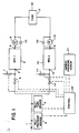
- Turning to Figure 1, an embodiment of an apparatus of the invention is shown in a block diagram, schematic form. That apparatus includes an
inlet conduit 1 through which a pressurized inlet gas mixture is supplied to the apparatus. That mixture may be conditioned bleed air from an aircraft engine. The bleed air may be conditioned by drying, filtering, and/or other steps before being supplied to conduit 1. The pressure and temperature of the gas applied throughconduit 1 are respectively sensed by apressure sensor 2 and atemperature sensor 3. Those sensors are of conventional construction and produce analog electrical signals as indications of the gas mixture pressure and temperature.Pressure sensor 2 is a conventional strain gauge type semiconductor pressure sensor.Temperature sensor 3 may be a resistance temperature detector (RTD). - The
conduit 1 divides into two identical legs. In one of them, an inlet valve 4, preferably a pneumatically piloted solenoid actuated diaphragm valve, controls the flow of the inlet gas to aninlet 5 of asorption bed 6. Avent valve 7 is also connected to theinlet 5 ofsorption bed 6 for venting the bed during the regeneration process. Valve 7 is also preferably a pneumatically piloted, solenoid actuated diaphragm valve. During the adsorption operation ofbed 6, valve 4 is open andvalve 7 is closed. Inlet gas flows intobed 6 throughinlet 5 and product gas flows out through anoutlet 8.Outlet 8 is connected through acheck valve 9 to a reserve tank 12 containing a volume of the product gas.Check valve 9 allows gas to flow frombed 6 to tank 12, but prevents backflows intobed 6 throughoutlet 8. A bypass 10 containing a flow restricting element, such as an orifice, is pneumatically connected in parallel withcheck valve 9. Bypass 10 allows a restricted flow of product gas into and out ofsorption bed 6 throughoutlet 8 and is used in the regeneration ofbed 6 as described below. - The sorption bed arrangement in the lower half of Figure 1 is identical to that in the upper half. Like elements are identified by similar reference numerals increased by ten. An
inlet valve 14 selectively supplies the inlet gas mixture toinlet 15 ofsorption bed 16. Avent valve 17 connected toinlet 15 is employed in the regeneration ofbed 16.Bed 16 includes anoutlet 18 connected to acheck valve 19. The product gas generated bysorption bed 16 is supplied throughcheck valve 19 to tank 12. Abypass 20 containing a flow restricting element is pneumatically connected in parallel withcheck valve 19 to allow a backflow of product gas tosorption bed 16 while that bed is being regenerated. Tank 12 functions as a reservoir and also smoothes surges in the pressure of the product gas that may be produced, for example, when a bed is taken out of adsorption service to be regenerated. Tank 12 includes an outlet conduit for transporting the product gas to other devices, such as regulators and/or breathing masks for aircraft crew members. - The arrangement of Figure 1 is highly schematic and drawn to aid understanding of the invention.
Sorption beds - In addition to the sensors and valving for the inlet and product gas, a
pressure sensor 21 for measuring the ambient pressure is provided. Likesensor 2,pressure sensor 21 is preferably a conventional strain gauge type semiconductor pressure sensor. - The apparatus of Figure 1 includes a
control unit 22 that is in electrical communication withsensors valves Control unit 22 receives the electrical signals from the sensors and employs them in calculations for controlling the adsorption and regeneration operations of the sorption bed apparatus.Control unit 22 responds by actuatingvalves -
Beds cycle bed 6 is operational, adsorbing a gas component and producing product gas. During a different part of thecycle bed 16 is adsorbing and producing product gas. That is, one bed is in service during part of the cycle and during that part of the cycle the other bed is off-line. During part of the time a bed is offline, it is regenerated by being depressurized, i.e., exposed to ambient pressure, and product gas is allowed to purge it by flowing through the bed in a backward direction, i.e., into the outlet and out through an opened vent valve. The backward flow of product gas aids the desorption by the bed of the adsorbed gas component to complete the regeneration process. Regeneration of an offline bed may begin immediately after a bed is taken out of service or may be delayed for an interval after the inlet valve to the bed has been closed. The duration of the cycle, the variable adsorption intervals of the beds, the variable regeneration intervals, and the timings of the intervals are determined and implemented bycontrol unit 22 in response to sensed data and stored adsorption and regeneration characteristic data. - At one point in an operation,
bed 6 may be adsorbing. Valve 4 is open andvalve 7 is closed so that an inlet gas mixture is supplied tobed 6 where one component of the gas mixture is being adsorbed. The product gas flows throughcheck valve 9 toward tank 12. At the end of the adsorption interval ofbed 6, as determined bycontrol unit 22, valve 4 is closed. Subsequently,valve 7 is opened to vent, i.e., depressurizebed 6.Bed 6 reaches a pressure at or near that of the ambient. That pressure may be below atmospheric whenvalve 7 is vented at a high altitude. About the same time thatbed 6 is taken out of service,bed 16 is put into operation by the opening ofvalve 14 and begins adsorbing a component of the inlet gas mixture. Theproduct gas bed 16 produces flows to tank 12 throughcheck valve 19. After depressurization ofbed 6, some of the product gas flows through bypass 10 and throughbed 6, in a direction opposite the flow during adsorption, and outopen valve 7. That reverse flow of purging gas occurs because of the high pressure of the product gas compared to the ambient beyondopen valve 7. The flowing product gas purges adsorbed gas frombed 6. Thus, the regeneration process includes a depressurization step followed by a purge step. At the conclusion of the purge step,valve 7 is closed. Ifbed 16 continues to produce product gas beforebed 6 is brought back into operation, that product gas pressurizesbed 6 through bypass 10. Eventually,bed 16 is taken out of adsorption service for regeneration by the closing ofvalve 14 andbed 6 is placed back into adsorbing operation by opening valve 4. All of these actions in one cycle are implemented bycontrol unit 22. - Besides receiving the sensor signals,
control unit 22 also stores the characteristics of the sorbent material employed insorption beds Control unit 22 includes a calculational capability for predicting the performance of the sorbent beds while adsorbing a component of a gas mixture under pressure and for predicting the degree of regeneration of the beds when depressurized and purged. These calculations are made based upon the information provided to controlunit 22 bysensors control unit 22 includes a microprocessor and associated programmable read-only memories. - In Figure 2, an arrangement of a
microprocessor 41, associatedsensors frequency control 43,memories valves Microprocessor 41 may be a conventional, commercially available microprocessor such as an Intel 8097. That type of microprocessor is particularly advantageous because it includes an eight channel multiplexer and a successive approximation analog-to-digital converter so that the multiple analog signals provided by the various sensors are easily converted to a digital format. In addition,microprocessor 41 linearizes the response of the sensors. The clock rate of the microprocessor is controlled by an external frequency control, shown as acrystal 43, for controlling the frequency of the basic oscillator within the microprocessor.Memory 45 is a programmable read-only memory (EPROM) for storing the program executed bymicroprocessor 41. The adsorption and regeneration characteristics of the sorption bed material as a function of ambient pressure and inlet gas mixture pressure and temperature are stored inmemory 45 for use in the valve control calculations carried out bymicroprocessor 41.Memory 47 is a static random access memory including an electrically erasable programmable read-only memory (RAM/EEPROM) in which calibration data for the sensors and fault code information are stored.Memory 47 also provides a scratch pad for computations. - As a result of the calculations performed by
microprocessor 41 employing stored and sensed information,valves microprocessor 41 are passed to bufferamplifiers valves microprocessor 41 includes a built-in test program for determining the proper operation of the electronics each time power is applied to the microprocessor and for periodically monitoring the status of the sensors. For example, when a sensor produces a signal that is outside a reasonable range, the sensor is assumed to have failed. The microprocessor then ignores the sensor signal and substitutes a worst case, extreme value as the sensor signal. This response ensures continued production of product gas, but at a reduced effi ciency. If a catastrophic failure is detected, the program defaults to a predetermined status for the valves. In either case, a status signal is produced and supplied to anindicator 57 as a warning of the existence of a failure and, possibly, its severity.Warning 57 may be a light that is illuminated upon the occurrence of a failure. In addition, a fault code is stored in a non-volatile memory for subsequent identification of the source of the failure. In the latter event, in the course of regular maintenance of the apparatus, the fault code discloses the abnormality that has occurred so that appropriate maintenance procedures can be carried out. Preferably, a catastrophic failure provides an immediate warning so that action can be taken. For an aircraft, the needed action may be switching to a backup supply of breathable air or a descent to an altitude where the oxygen content of the ambient air is acceptable. - Figure 3 is a flow diagram illustrating a valve operating sequence consisting of
steps 60 through 75. An adsorption process for a first bed begins atstep 60 where the inlet valve is open and ends atstep 66 where that inlet valve is closed. In between those steps, there is avariable length delay 100 atstep 61 after which the regeneration process for the second bed begins with the opening of its vent valve instep 62. That valve remains open during a purginginterval 63 and is closed instep 64. During this purging interval, the first bed is continuing to adsorb a gas component. That adsorption continues until the expiration of the delay interval ofstep 65, namely, the total adsorption interval less the sum of the purge interval and the initial delay ofstep 61. Afurther delay 200 takes place between the adsorption operations of the first and second beds atstep 67. Certain of the delays are numbered in Figure 3 for identification, but those identifying numbers are no indication of the duration of the delays. In fact, in accordance with the invention, all of the delays are variable in duration and the durations are determined bycontrol unit 22 as hereinafter described to optimize performance. - After the completion of a
variable length delay 200 instep 67, the sequence of steps 60-66 are repeated as steps 68-74, but with the first and second beds interchanged. Thereafter, atstep 75 after a delay corresponding to the delay ofstep 67, the sequence returns to step 60 and is repeated. In this preferred valve sequencing operation, calculated changes in the optimum adsorption and purge intervals based on updated information on the pressure and temperature of the inlet gas mixture can be implemented at the end of any delay interval. That is, at the beginning and end of the various steps,control unit 22 can make adjustments in the timing of the valve sequencing to ensure optimum production of product gas in the adsorption/regeneration cycle. Other valving sequences can be employed. For example, while Figure 3 shows sequential adsorption intervals for the separate beds, in some situations the adsorption intervals could overlap in time. In that case, for example, delay 200 in the Figure 3 flow chart would be negative. - The operation of the valves under the control of
unit 22 ensures that the optimum quantity of product gas is generated when the inlet gas is subject to relatively wide swings in temperature and pressure and when its quantity is limited. For example, in an application in an aircraft, the nominal average quantity of compressed air available as a bleed gas from an engine may be limited to 0.68 kg/min (1.5 lbs/min). It is therefore of substantial importance that an optimum quantity of a breathable gas mixture be produced from a limited quantity, highly variable source. That result is achieved in the invention by controlling and changing the adsorption and purge intervals in response to changes in ambient pressure and in the pressure and temperature of the inlet gas mixture. - In various applications of the invention, different tests can be applied in determining the adsorption and purging intervals depending upon the mode of operation. Two examples of operational modes, both for producing breathable air for aircraft crews, are described below. In the first example, it is assumed that the product gas flowing out of the sorption beds is supplied directly to the crew members without dilution. In order to meet crew needs, the product gas must contain at least a specified oxygen content and be provided at a specified minimum flow rate. That oxygen content is expressed in terms of a partial pressure of oxygen which, for example, may be 200 mm Hg and a typical minimum flow rate may be 100 standard liters per minute (slpm). In order to select the appropriate adsorption and purge intervals to be employed at any particular time, time intervals t₀, t₁, t₂, t₄, and t₅ are repeatedly calculated by the control unit in response to repeated measurements of the ambient pressure and of the conditions of the inlet gas. Time interval t₃ is also employed in determining the appropriate adsorption and purging intervals.
- t₀ is the minimum adsorption interval. In each cycle of the apparatus a certain amount of the inlet gas is wasted, i.e., none of it becomes product gas. For example, when one bed is taken offline it contains a quantity of inlet gas. When that bed is vented, the inlet gas flows out without having produced product gas. A shorter cycle time means more frequent valve operation, including venting, and more lost, i.e., unused, inlet gas. That is, more gas is consumed, both in producing product gas and in waste, as the cycle time is shortened. When the quantity per unit time of inlet gas is limited, at a certain adsorption interval, t₀, all of the inlet gas that is allocated to the extraction apparatus is consumed. Therefore, the adsorption interval, i.e., the duration of adsorption service by each bed in one cycle, cannot be shorter than t₀.
- t₁ is the purging interval required to purge a bed with a quantity of product gas that exceeds the minimum purging quantity required for efficient regeneration by a predetermined excess amount, e.g., 20 percent, plus the time needed for operating the valves. t₁ fixes the minimum time interval for adsorption by one bed while another bed is being purged with the specified excess over the minimum quantity of product gas necessary for efficient regeneration. Regeneration efficiency depends upon the pressure swing of the beds, here the difference between the inlet gas pressure and the ambient pressure, and the quantity of purging gas that flows. The purging gas flow rate is a function of inlet pressure. Thus, the purging interval determines the quantity of purging gas that flows.
Control unit 22 can calculate the purging interval, taking into account the required quantity of purge gas, from the stored bed characteristics and sensed pressures, that restores a bed to a specified degree of adsorption performance. As used here, the term efficient regeneration refers to purging that is just sufficient to restore a bed to that specified degree of adsorption performance. - t₂ is the adsorption interval that will produce a sufficient quantity of product gas to purge the offline regenerating bed with a specified excess quantity of product gas, e.g., 1.2 times the minimum quantity of product gas needed for efficient regeneration, and simultaneously produce product gas containing a minimum specified partial pressure of a desired component at a specified minimum flow rate. t₂ establishes an upper limit for the adsorption interval.
- t₃ is the minimum adsorption interval allowable. The minimum allowable adsorption interval is fixed for a particular apparatus configuration and may be, for example, about 3 seconds. Different values of t3 apply to different apparatus configurations.
- t₄ is the interval required to purge a regenerating bed with the minimum quantity of product gas for efficient regeneration plus the time needed for operating the valves. t₄ is similar to t₁ except that the minimum quantity of product gas for efficient regeneration is assumed in calculating t₄, rather than the excess that is assumed in calculating t₁.
- t₅ is the adsorption interval that will produce a sufficient quantity of product gas to purge the offline regenerating bed with the minimum quantity of product gas necessary for efficient regeneration and simultaneously produce product gas with the minimum specified partial pressure of a desired component at the specified minimum flow rate. t₅ establishes an upper limit for adsorption interval.
- Time intervals t₀, t₁, t₂, t₄, and t₅ are calculated in
control unit 22 by retrieving the stored sorbent bed material characteristics which are a function of the ambient pressure and the temperature and pressure of the inlet gas. Those characteristics predict the quantity and quality of the product gas that is produced for various ambient pressures and inlet gas conditions, taking into account the geometry and the size of the particular sorbent beds employed. Those characteristics allow the calculation of the time intervals t₀, t₁, t₂, t₄, and t₅, taking into account the declining efficiency of the sorbent material as the adsorption process is carried out and the effectiveness of the regeneration process. Thus, the length of the adsorption interval can be chosen based upon a computation that shortens or lengthens that interval so that the optimum quantity of acceptable quality product gas is obtained. In the invention,control unit 22 automatically and repetitively determines the adsorption and purge intervals based on each set of calculated values for t₀, t₁, t₂, t₄, and t₅, and t₃ to optimize product gas production. In the determinations, t₄ and t₅ are used at extreme operating conditions (i.e., low inlet gas pressure, high inlet gas temperature, high ambient pressure) where the difficulty in obtaining the required performance is the greatest. - The choice of the adsorption interval is made based upon the calculated value of t₂, the maximum adsorption interval when an extended purge can be carried out during regeneration. That choice is desirable to obtain superior adsorption performance. Interval t₂ is calculated, as described above, based upon the characteristics of the inlet gas supply to the apparatus for extraction of a component. If that value, t₂, is greater than or equal to the maximum of t₀, t₁, and t₃, then an adsorption interval of that length will provide an operational cycle and t₂ is chosen as the adsorption interval. That choice means that one bed can adsorb a component from the inlet gas while another bed completes an entire regeneration process including purging with an excess quantity of product gas. In that case, the purge portion of the regeneration process is set equal to t₁ less the valve opening and closing times. If t₂ is not greater than or equal to the maximum of t₀, t₁, and t₃, then the control unit establishes as the adsorption interval the maximum of t₃, t₄, and t₅. This selection assures that the adsorption interval at least equals the minimum allowable interval and, if possible, sets the adsorption interval to exceed the purge interval when the minimum quantity of product gas for efficient regeneration is employed in the purge. In this case, the purge interval is set equal to t₄ less the valve opening and closing time.
- The foregoing example concerns, for an application for the crew of an aircraft, the supplying of a breathable gas directly to the crew members. When inlet gas supply and conditions permit the production of an excess quantity of product gas, that excess product gas can be stored in a reservoir for later use while the remainder of the currently produced product gas is supplied to crew members. Whether the product gas can be stored also depends upon its pressure, the pressure of the gas already stored in the reservoir, and the quality of the product gas. In this example, a diluting regulator is usually employed that dilutes the product gas so that a gas mixture of desired concentration reaches the crew members.
- In this second example, intervals t₀ through t₆ are initially calculated. Intervals t₀, t₁, t₃, and t₄ have the same definitions as the corresponding intervals in the first example. Intervals t₁ and t₄ are calculated in the same way as the corresponding times described above for the first example. In this example, in which the product gas may charge a reservoir and is diluted to provide a breathable gas mixture, the time t₂ is different from that of the preceding example. In this second example, a required minimum flow rate to the diluting regulator of an assumed minimum quality, e.g., 93% oxygen content, and to the reservoir are specified. These desired flows are used to calculate an interval t₂, which is an adsorption interval that produces the desired flow assuming that an excess volume of product gas is employed in purging regenerating beds. In a specific example, 120 percent of the minimum quantity of product gas necessary for efficient regeneration of a bed is employed to purge a regenerating bed. The calculated value of t₂ is thus the maximum adsorption interval for a single bed while the reservoir is being charged. An interval t₅ is calculated as the adsorption interval when the required flow rate is provided to the diluting regulators, but without charging the reservoir, assuming that an excess quantity of product gas over that required for efficient regeneration is employed in purging a regenerating sorption bed. This interval t₅ is the maximum adsorption interval when the reservoir is not being filled. An interval t₆ is also calculated which is similar to t₅, except that the purge step of the regeneration process employs only the minimum needed volume of product gas to purge a regenerating bed efficiently.
- Because this second example includes the additional option of charging a reservoir, the determination of an adsorption interval from the intervals t₀ through t₆ is more complicated than in the first example. A sensor for measuring the pressure of the product gas flowing from the beds and another sensor for measuring the pressure of the product gas in the reservoir may be needed. That pressure information is important in the selection of the adsorption and purging intervals. However, since those sensors (which are not shown in Figure 1) measure pressure directly, they do not increase the complexity of the apparatus excessively.
- If t₂, an adsorption time when the reservoir is being charged and excess purge quantities are employed, is greater than or equal to the maximum of t₀, t₁, and t₃, and the pressure in the reservoir is less than the pressure of the product gas, then t₂ is chosen as the adsorption interval. The purge interval is then chosen equal to t₁ less the valve switching time. In this mode of operation, the reservoir can be filled. If, on the other hand, t₂ is not at least equal to the maximum of t₀, t₁, and t₃, or the pressure of the product gas does not exceed the pressure in the reservoir, a secondary test is applied. If t₅ is greater than or equal to the maximum of t₀, t₁, and t₃, then sufficient product gas can be produced to supply breathing needs, even though there may not be sufficient excess product gas to charge the reservoir. The adsorption interval is then established as t₅ and the purge interval is established at t₁ minus the valve switching time, the same purge interval as in the prior situation of this second example. Both of the foregoing situations assume purging with an excess quantity of product gas. If t₅ is not at least equal to the maximum of t₀, t₁, and t₃, then an adsorption interval of t₅ will not provide a workable cycle. In that case, to optimize product gas production, only the minimum quantity of product gas is used in the purging step. The adsorption interval is thus set equal to the maximum of t₀, t₄, and t₆. As in the first example, this cycling arrangement ensures that the regeneration process takes no more time than the adsorption process. In this third situation, the purge interval is set to t₄ less the valve switching time. In this third and default option of the second example, the product gas reservoir cannot be filled.
- The two examples described do not exhaust the methods of applying the invention. However, those examples demonstrate the utilization of the sorption beds with a limited and highly variable supply of the inlet gas mixture to maximize the efficiency of the sorption process and optimize the production of product gas even at extreme air and gas pressures and temperatures. While the two examples have each explained a single determination of an adsorption interval, the calculations and determinations are made repetitively in real time in the apparatus. For example, ambient pressure and the temperature and pressure of the inlet gas mixture may be measured twenty times per minute with corresponding determinations of optimized adsorption and purge intervals. The intervals actually employed are changed, usually at the end of a valve state change, to continually optimize bed efficiency and product gas generation. The two examples have also described apparatus employing two sorption beds that are alternatively operated and regenerated. The invention can also be applied to apparatus including more than two sorption beds.
- Because the invention responds to changes in ambient pressure and the temperature and pressure of the inlet gas, its product gas production is optimized. That is, for particular capacity beds, the maximum possible quantity of product gas can be produced. Bed capacity need not be chosen to be large enough to handle the maximum expected inlet gas mixture flow. Instead, smaller, lighter beds can be employed to produce quantities of product gas that are comparable to those produced by much larger beds. This result can be achieved because, at large inlet gas mixture flows, the adsorption interval and cycle time are shortened, pressing the beds to perform at their maximum adsorption rates. At lower inlet gas flow rates, the adsorption interval is lengthened. Again, the beds are pressed to maximum performance for the conditions, but with emphasis on longer adsorption intervals rather than on maximum adsorption rates.
- Application of the novel apparatus and method may require auxiliary equipment. Figure 4 shows a block diagram of the invention used in a breathable air supply system for an aircraft crew. This system includes two breathing masks (not shown) each of which is fed by a
separate breathing regulator 78.Breathing regulators 78 supply product gas directly to the masks or mix the product gas with a diluting gas depending upon the selected operational mode. At the inlet side of the apparatus, afilter 80 is employed to remove aerosols and particulates from air, in this case conditioned air bled from the engine of the aircraft. The filtered gas mixture is supplied to aconcentrator 82, which is the dual bed sorption apparatus described in detail above. The product gas is supplied to aparticulate filter 84 which removes any particles of the sorption bed that are carried from the bed by the flowing gas. The flowing product gas is delivered to areservoir valve 86 which controls the flow of product gas into and out of a reservoir 88. Reservoir 88 provides a backup supply of product gas to supplement or supplant the product ofconcentrator 82, if necessary. - An oxygen monitor 90 may be employed to monitor the quality of the product gas being supplied to the
breathing regulator 78. That oxygen purity information is supplied to controlunit 92 which comprises the microprocessor and associated circuitry described above. The dashed lines in Figure 4 indicate electrical connections for supplying information to controlunit 92 and for controlling the various valves. Thus,control unit 92 can determine the pressure in reservoir 88 and the purity and pressure of the product gas to determine whether product gas can be added to the reservoir or should be withdrawn from it to supplement other product gas being produced. Likewise, thecontrol unit 92 may actuate breathingregulators 78, possibly in response to crew member choices, so that product gas is supplied directly to the masks or is mixed with a diluting gas mixture.Control unit 92 also includes a systemfailure warning indicator 94, such as a light, to warn the crew of a catastrophic failure of the system requiring descent of the aircraft to an altitude where breathable air is available before the product gas stored in reservoir 88 is exhausted. - The invention has been described with respect to certain preferred embodiments. Various modifications and additions will occur to those of skill in the art. Accordingly, the scope of the invention is limited solely by the following claims.
Claims (14)
first and second sorption beds (6,16), each bed having an inlet (5,15) for admitting air and an outlet (8,18) for discharging air, respectively, said beds for, in an operating condition, adsorbing nitrogen from air and supplying an oxygen-enriched mixture as a product gas, and for, in a regenerating condition, desorbing adsorbed nitrogen from said beds;
an inlet conduit (1) for supplying the inlet gas mixture to said inlets (5,15) of said first and second beds (6,16);
first and second inlet valves (4,14) connected between said inlet conduit (1) and said inlets (5,15) of said first and second beds (6,16), respectively, for selectively admitting air to said first and second beds (6,16);
first and second vent valves (7,17) in fluid communication with said first and second beds (6,16), respectively, for venting said first and second beds (6,16);
means for admitting (9,10,19,20) product gas from one bed in an operating condition to the other bed in a regenerating condition to purge said other bed;
first and second sensors (2,3) in fluid communication with said inlet conduit (1) for sensing the pressure and temperature, respectively, of the air supplied to said first and second inlet valves (4,14);
a third sensor (21) for sensing ambient pressure proximate said first and second beds (6,16); and
control means (22), storing the sorption characteristics of said first and second beds (6,16) as a function of ambient pressure and the temperature and pressure of the air, for determining, in response to said first, second, and third sensors (2,3,21) and the sorption characteristics of said first and second beds (6,16), intervals for adsorption by and purging of said first and second beds (6,16) and for actuating said first and second inlet and vent valves (4,14,7,17) for cycling said first and second beds (6,16) between operating and regenerating conditions in accordance with the determined adsorption and purging intervals to optimize the production of product gas for the sensed inlet air and ambient conditions.
extracting a component from a pressurized inlet gas mixture by passing it through a first sorbent bed during an adsorption interval thereby producing a product gas mixture;
regenerating a second sorbent bed during the adsorption interval of the first sorbent bed including passing a quantity of the product gas from the first sorbent bed through the second sorbent bed in a reverse direction during a purging interval while the second sorbent bed is vented to the ambient;
alternating the first and second beds between adsorption and regeneration operations;
sensing the ambient pressure and the temperature and pressure of the pressurized inlet gas mixture;
determining from the sensed ambient pressure and the temperature and pressure of the pressurized inlet gas mixture and from the sorption characteristics of the sorbent beds the length of adsorbing and purging intervals that optimize the production of product gas; and
adjusting the adsorption and purging intervals of the first and second sorption beds to the respective determined intervals that optimize the production of product gas.
Applications Claiming Priority (2)
| Application Number | Priority Date | Filing Date | Title |
|---|---|---|---|
| US285162 | 1988-12-16 | ||
| US07/285,162 US4927434A (en) | 1988-12-16 | 1988-12-16 | Gas component extraction |
Publications (2)
| Publication Number | Publication Date |
|---|---|
| EP0375220A1 true EP0375220A1 (en) | 1990-06-27 |
| EP0375220B1 EP0375220B1 (en) | 1995-08-09 |
Family
ID=23093024
Family Applications (1)
| Application Number | Title | Priority Date | Filing Date |
|---|---|---|---|
| EP89312816A Expired - Lifetime EP0375220B1 (en) | 1988-12-16 | 1989-12-08 | Gas component extraction |
Country Status (5)
| Country | Link |
|---|---|
| US (1) | US4927434A (en) |
| EP (1) | EP0375220B1 (en) |
| DE (1) | DE68923773T2 (en) |
| ES (1) | ES2075064T3 (en) |
| GB (1) | GB2225964B (en) |
Cited By (17)
| Publication number | Priority date | Publication date | Assignee | Title |
|---|---|---|---|---|
| FR2654009A1 (en) * | 1989-11-04 | 1991-05-10 | Draegerwerk Ag | PRESSURE VARIATION ADSORPTION INSTALLATION. |
| FR2691646A1 (en) * | 1992-06-01 | 1993-12-03 | Pall Corp | Separation of components of fluid mixtures in an aircraft. |
| EP0658365A1 (en) * | 1993-12-16 | 1995-06-21 | Praxair Technology, Inc. | Tuning of vacuum pressure swing adsorption systems |
| FR2766384A1 (en) * | 1997-07-25 | 1999-01-29 | Air Liquide | REGULATION OF A PSA PROCESS |
| EP0882484A3 (en) * | 1997-06-03 | 1999-03-10 | Litton Systems, Inc. | Oxygen concentrator with adsorption beds' duty cycle control and self-test |
| FR2785554A1 (en) * | 1998-11-09 | 2000-05-12 | Air Liquide | PSA OR VSA UNIT AT A RATE AND PRODUCTION PRESSURE JOINTLY REGULATED |
| FR2805760A1 (en) * | 2000-03-02 | 2001-09-07 | Zedrys Zeolite Drying System | Reversible solid/gas adsorption process, comprises matching adsorption capacity of reactor to evaporation capacity of product to be adsorbed |
| EP1029577A3 (en) * | 1999-02-19 | 2002-11-06 | Teijin Limited | Apparatus for producing oxygen enhanced gas from air |
| FR2841152A1 (en) * | 2002-06-19 | 2003-12-26 | Air Liquide | PROCESS FOR TREATING AT LEAST ONE PRESSURE MODULATION ADSORPTION LOAD GAS |
| FR2880328A1 (en) * | 2005-01-06 | 2006-07-07 | Air Liquide | On-board oxygen generating system operation verifying method for e.g. cargo aircraft, involves deducting information about operation of oxygen generating system from result obtained by controlling one sub-component of system |
| WO2006100398A1 (en) * | 2005-03-25 | 2006-09-28 | L'air Liquide, Societe Anonyme Pour L'etude Et L'exploitation Des Procedes Georges Claude | Method of adjusting an installation for the adsorption treatment of a gas |
| DE102006013538A1 (en) * | 2006-03-24 | 2007-10-04 | DRäGER AEROSPACE GMBH | Pressure regulator for emergency oxygen supply system in aircraft, has pressure sensor arranged at output side of arrangement of two valves and controller connected signally with pressure sensor, where controller controls valves |
| EP2628521A1 (en) * | 2012-02-14 | 2013-08-21 | Air Liquide Medical G.m.b.H. | Facility for on-site production of a medical gas using a three-way solenoid valve connected to a purging line |
| CN104977232A (en) * | 2015-07-10 | 2015-10-14 | 苏州华达仪器设备有限公司 | Gas buffer apparatus of laser particle dust counter |
| WO2016032449A1 (en) * | 2014-08-27 | 2016-03-03 | New York Air Brake, LLC | Improved control of an air dryer regeneration cycle |
| EP3069779A1 (en) * | 2015-03-19 | 2016-09-21 | Linde Aktiengesellschaft | Method for the adsorptive elimination of a component from a gas mixture |
| US9644893B2 (en) | 2014-08-27 | 2017-05-09 | New York Air Brake, LLC | Control of an air dryer regeneration cycle |
Families Citing this family (56)
| Publication number | Priority date | Publication date | Assignee | Title |
|---|---|---|---|---|
| GB8907447D0 (en) * | 1989-04-03 | 1989-05-17 | Normalair Garrett Ltd | Molecular sieve-type gas separation systems |
| US5042994A (en) * | 1990-05-25 | 1991-08-27 | Union Carbide Industrial Gases Technology Corporation | Control of pressure swing adsorption operations |
| US5148374A (en) * | 1990-06-19 | 1992-09-15 | Icc Technologies, Inc. | Desiccant space conditioning control system and method |
| US5258056A (en) * | 1991-09-27 | 1993-11-02 | The Boc Group, Inc. | PSA system with product turndown and purity control |
| US5323624A (en) * | 1992-11-13 | 1994-06-28 | United Technologies Corporation | Filtered environmental control system |
| GB9304858D0 (en) * | 1993-03-10 | 1993-04-28 | Pall Corp | Gas supply systems |
| US5549736A (en) * | 1994-01-19 | 1996-08-27 | Litton Systems, Inc. | Modular, stackable pressure swing absorption concentrator |
| US5476000A (en) * | 1994-03-31 | 1995-12-19 | Hewlett-Packard Company | Retention time stability in a gas chromatographic apparatus |
| US5593478A (en) * | 1994-09-28 | 1997-01-14 | Sequal Technologies, Inc. | Fluid fractionator |
| GB9524721D0 (en) * | 1995-12-02 | 1996-01-31 | Normalair Garrett Ltd | Molecular sieve type gas separation apparatus |
| US5604991A (en) * | 1996-02-06 | 1997-02-25 | Westinghouse Air Brake Company | Switching and purging mechanism for a twin tower air dryer |
| US6063169A (en) * | 1996-05-10 | 2000-05-16 | Litton Systems, Inc. | Control means for molecular sieve on-board oxygen generator |
| US5661987A (en) * | 1996-10-25 | 1997-09-02 | Pacific Consolidated Industries | Three-bed nonimmobilized rapid pressure-swing adsorber |
| US5827358A (en) * | 1996-11-08 | 1998-10-27 | Impact Mst, Incorporation | Rapid cycle pressure swing adsorption oxygen concentration method and apparatus |
| US5853455A (en) * | 1997-04-14 | 1998-12-29 | Jordan Technologies, Inc. | Vapor recovery system with continuous inlet monitoring |
| US5871564A (en) * | 1997-06-16 | 1999-02-16 | Airsep Corp | Pressure swing adsorption apparatus |
| US5989313A (en) * | 1997-12-19 | 1999-11-23 | Praxair Technology, Inc. | Method for operation of an air prepurifier which takes into account inlet air conditions |
| WO2000074819A1 (en) | 1999-06-04 | 2000-12-14 | Flair Corporation | Rotating drum adsorber process and system |
| FR2798075B1 (en) * | 1999-09-03 | 2001-11-09 | Air Liquide | CONDUCTING A THERMAL REGENERATION AIR PURIFICATION SYSTEM |
| US6352068B1 (en) * | 1999-12-27 | 2002-03-05 | Honda Giken Kogyo Kabushiki Kaisha | Method and apparatus for reducing oxides of nitrogen in the exhaust gas of an internal combustion engine |
| US6277174B1 (en) * | 2000-01-07 | 2001-08-21 | Praxair Technology, Inc. | Low pressure ratio VPSA plant tuning and balancing system |
| US6375722B1 (en) * | 2000-08-22 | 2002-04-23 | Henderson Engineering Co., Inc. | Heat of compression dryer |
| GB0123310D0 (en) * | 2001-09-28 | 2001-11-21 | Honeywell Normalair Garrett | Breathing gas supply system |
| US6722352B2 (en) * | 2001-11-06 | 2004-04-20 | Praxair Technology, Inc. | Pressure-swing adsorption system for internal combustion engines |
| FR2835932B1 (en) * | 2002-02-13 | 2004-03-19 | Air Liquide | METHOD FOR CONTROLLING AN ADSORPTION GAS TREATMENT PLANT AND CORRESPONDING TREATMENT PLANT |
| GB0204886D0 (en) * | 2002-03-01 | 2002-04-17 | Honeywell Normalair Garrett | Breathing gas supply system |
| US6669758B1 (en) | 2002-06-27 | 2003-12-30 | Carleton Life Support Systems, Inc. | Variable inlet air restriction for composition control of product gas |
| US6712876B2 (en) * | 2002-08-27 | 2004-03-30 | Litton Systems, Inc. | Oxygen concentrator system with altitude compensation |
| US6712877B2 (en) * | 2002-08-27 | 2004-03-30 | Litton Systems, Inc. | Oxygen concentrator system |
| GB0230098D0 (en) * | 2002-12-24 | 2003-01-29 | Honeywell Normalair Garrett | Method of controlling a gas absorption apparatus |
| US7036521B2 (en) * | 2003-04-27 | 2006-05-02 | Carleton Life Support Systems, Inc. | Air conserving slide valve |
| US7128064B2 (en) * | 2004-02-20 | 2006-10-31 | Heider James E | Method and apparatus to provide oxygen enriched air to the intake manifold of an internal combustion engine |
| US7445663B1 (en) | 2004-10-21 | 2008-11-04 | Sunrise Medical Hhg Inc. | Energy efficient oxygen concentrator |
| US7402287B2 (en) * | 2004-12-17 | 2008-07-22 | Texaco Inc. | Apparatus and methods for producing hydrogen |
| US7354463B2 (en) * | 2004-12-17 | 2008-04-08 | Texaco Inc. | Apparatus and methods for producing hydrogen |
| US7354464B2 (en) | 2004-12-17 | 2008-04-08 | Texaco Inc. | Apparatus and method for producing hydrogen |
| US20060196356A1 (en) * | 2005-02-04 | 2006-09-07 | Henderson Terry D | Single tower gas dryer with flowing desiccant stream |
| US20060196361A1 (en) * | 2005-02-04 | 2006-09-07 | Henderson Terry D | Single tower gas dryer with flowing desiccant stream |
| EP1996737A2 (en) * | 2006-02-06 | 2008-12-03 | Hyradix Inc. | Integrated reformer and batch annealing processes and apparatus therefor |
| GB2436151B (en) * | 2006-03-15 | 2009-09-30 | Honeywell Normalair Garrett | Method of controlling a gas separating apparatus |
| DE102006052586B4 (en) * | 2006-11-08 | 2008-07-03 | Schott Solar Gmbh | Method and device for cleaning the exhaust gases of a silicon thin-film production plant |
| US20090065007A1 (en) | 2007-09-06 | 2009-03-12 | Wilkinson William R | Oxygen concentrator apparatus and method |
| US20120055477A1 (en) * | 2010-09-07 | 2012-03-08 | Wilkinson William R | Oxygen concentrator apparatus configured for high altitude use |
| US8888902B2 (en) * | 2011-08-26 | 2014-11-18 | Separation Design Group Llc | Portable oxygen enrichment device and method of use |
| US8758480B2 (en) * | 2011-09-09 | 2014-06-24 | Torosoleil, Llc | Dynamic and continuous control for pressure swing adsorption |
| US9138557B2 (en) | 2012-10-12 | 2015-09-22 | Inova Labs, Inc. | Dual oxygen concentrator systems and methods |
| NZ707064A (en) | 2012-10-12 | 2017-11-24 | Inova Labs Inc | Method and systems for the delivery of oxygen enriched gas |
| EP2906280B1 (en) | 2012-10-12 | 2018-09-26 | Inova Labs, Inc. | Oxygen concentrator systems and methods |
| GB2507050B (en) * | 2012-10-16 | 2014-09-17 | Nano Porous Solutions Ltd | Pressure swing adsorption apparatus |
| US8979982B2 (en) | 2013-05-01 | 2015-03-17 | Jordan Technologies, Llc | Negative pressure vapor recovery system |
| US9440179B2 (en) | 2014-02-14 | 2016-09-13 | InovaLabs, LLC | Oxygen concentrator pump systems and methods |
| EP3122411B1 (en) * | 2014-03-28 | 2019-07-10 | Caire Inc. | Controlling oxygen concentrator timing cycle based on flow rate of oxygen output |
| US9782715B2 (en) * | 2014-12-30 | 2017-10-10 | Pacific Consolidated Industries, Llc | Load following single bed reversing blower adsorption air separation system |
| US11458274B2 (en) | 2016-05-03 | 2022-10-04 | Inova Labs, Inc. | Method and systems for the delivery of oxygen enriched gas |
| ES2751176B2 (en) * | 2018-09-29 | 2021-07-21 | Bluegeneration S L | Installation and procedure to recover gaseous substances from gaseous streams |
| GB202013603D0 (en) * | 2020-08-28 | 2020-10-14 | Honeywell Int Inc | Obogs controller |
Citations (4)
| Publication number | Priority date | Publication date | Assignee | Title |
|---|---|---|---|---|
| US434957A (en) * | 1890-08-26 | Automatic ink-distributer for printing-presses | ||
| EP0046369A1 (en) * | 1980-08-18 | 1982-02-24 | Normalair-Garrett (Holdings) Limited | Molecular sieve type gas separation systems |
| EP0080300A1 (en) * | 1981-11-13 | 1983-06-01 | Normalair-Garrett (Holdings) Limited | Molecular sieve type gas separation systems |
| US4718020A (en) * | 1985-05-30 | 1988-01-05 | Pall Corporation | Fault recovery procedure for heat-reactivated dryer |
Family Cites Families (24)
| Publication number | Priority date | Publication date | Assignee | Title |
|---|---|---|---|---|
| US3922149A (en) * | 1974-01-30 | 1975-11-25 | Garrett Corp | Oxygen air enrichment method |
| US4496376A (en) * | 1978-01-26 | 1985-01-29 | Litton Systems, Inc. | Variable area molecular sieve container having a thermal control system |
| US4197095A (en) * | 1978-08-31 | 1980-04-08 | Pall Corporation | Heatless adsorbent fractionators with microprocessor cycle control and process |
| US4231768A (en) * | 1978-09-29 | 1980-11-04 | Pall Corporation | Air purification system and process |
| US4247311A (en) * | 1978-10-26 | 1981-01-27 | Pall Corporation | Downflow or upflow adsorbent fractionator flow control system |
| DE2923325A1 (en) * | 1979-06-08 | 1980-12-11 | Linde Ag | CYCLICAL ADSORPTION METHOD FOR DISASSEMBLING A GAS MIXTURE |
| US4351649A (en) * | 1979-11-23 | 1982-09-28 | Texaco Inc. | Control system for gas dehydrators |
| DE2951626C2 (en) * | 1979-12-21 | 1986-10-09 | Drägerwerk AG, 2400 Lübeck | Device for breaking down a gas mixture |
| US4349357A (en) * | 1980-06-23 | 1982-09-14 | Stanley Aviation Corporation | Apparatus and method for fractionating air and other gaseous mixtures |
| DE3029080A1 (en) * | 1980-07-31 | 1982-02-18 | Linde Ag, 6200 Wiesbaden | METHOD AND DEVICE FOR PROVIDING BREATH GAS |
| DE3200679C1 (en) * | 1982-01-13 | 1983-07-28 | Drägerwerk AG, 2400 Lübeck | Mixing device |
| US4648888A (en) * | 1982-07-09 | 1987-03-10 | Hudson Oxygen Therapy Sales Co. | Oxygen concentrator |
| US4516424A (en) * | 1982-07-09 | 1985-05-14 | Hudson Oxygen Therapy Sales Company | Oxygen concentrator monitor and regulation assembly |
| US4627860A (en) * | 1982-07-09 | 1986-12-09 | Hudson Oxygen Therapy Sales Company | Oxygen concentrator and test apparatus |
| US4546442A (en) * | 1982-11-24 | 1985-10-08 | Pall Corporation | Microcomputer control system for desiccant dryer |
| US4479815A (en) * | 1983-03-09 | 1984-10-30 | Pall Corporation | Pneumatic controller and alarm for adsorbent fractionaters, particularly dessicant dryers |
| DE3469491D1 (en) * | 1983-03-31 | 1988-04-07 | Normalair Garrett Ltd | Molecular sieve type gas separation systems |
| EP0129304B1 (en) * | 1983-06-15 | 1988-07-13 | Normalair-Garrett (Holdings) Limited | Molecular sieve type gas separation systems |
| US4545790A (en) * | 1983-08-11 | 1985-10-08 | Bio-Care, Incorporated | Oxygen concentrator |
| US4681602A (en) * | 1984-12-24 | 1987-07-21 | The Boeing Company | Integrated system for generating inert gas and breathing gas on aircraft |
| DE3672510D1 (en) * | 1985-02-22 | 1990-08-16 | Normalair Garrett Ltd | PNEUMATIC PARTIAL PRESSURE SENSOR. |
| GB8528249D0 (en) * | 1985-11-15 | 1985-12-18 | Normalair Garrett Ltd | Molecular sieve bed containers |
| US4698075A (en) * | 1986-06-05 | 1987-10-06 | International Oxygen Company, Inc. | Control system for fluid absorption systems and the like |
| GB8623605D0 (en) * | 1986-10-01 | 1986-11-05 | Normalair Garrett Ltd | Aircraft on-board gas generating apparatus |
-
1988
- 1988-12-16 US US07/285,162 patent/US4927434A/en not_active Expired - Fee Related
-
1989
- 1989-12-08 GB GB8927770A patent/GB2225964B/en not_active Expired - Fee Related
- 1989-12-08 DE DE68923773T patent/DE68923773T2/en not_active Expired - Fee Related
- 1989-12-08 EP EP89312816A patent/EP0375220B1/en not_active Expired - Lifetime
- 1989-12-08 ES ES89312816T patent/ES2075064T3/en not_active Expired - Lifetime
Patent Citations (4)
| Publication number | Priority date | Publication date | Assignee | Title |
|---|---|---|---|---|
| US434957A (en) * | 1890-08-26 | Automatic ink-distributer for printing-presses | ||
| EP0046369A1 (en) * | 1980-08-18 | 1982-02-24 | Normalair-Garrett (Holdings) Limited | Molecular sieve type gas separation systems |
| EP0080300A1 (en) * | 1981-11-13 | 1983-06-01 | Normalair-Garrett (Holdings) Limited | Molecular sieve type gas separation systems |
| US4718020A (en) * | 1985-05-30 | 1988-01-05 | Pall Corporation | Fault recovery procedure for heat-reactivated dryer |
Cited By (30)
| Publication number | Priority date | Publication date | Assignee | Title |
|---|---|---|---|---|
| FR2654009A1 (en) * | 1989-11-04 | 1991-05-10 | Draegerwerk Ag | PRESSURE VARIATION ADSORPTION INSTALLATION. |
| FR2691646A1 (en) * | 1992-06-01 | 1993-12-03 | Pall Corp | Separation of components of fluid mixtures in an aircraft. |
| ES2072195A2 (en) * | 1992-06-01 | 1995-07-01 | Pall Corp | Removal in aircraft of components from fluid mixtures |
| US5429663A (en) * | 1992-06-01 | 1995-07-04 | Pall Corporation | Removal in aircraft of components from fluid mixtures |
| EP0658365A1 (en) * | 1993-12-16 | 1995-06-21 | Praxair Technology, Inc. | Tuning of vacuum pressure swing adsorption systems |
| EP0882484A3 (en) * | 1997-06-03 | 1999-03-10 | Litton Systems, Inc. | Oxygen concentrator with adsorption beds' duty cycle control and self-test |
| EP0894521A1 (en) * | 1997-07-25 | 1999-02-03 | L'air Liquide, Societe Anonyme Pour L'etude Et L'exploitation Des Procedes Georges Claude | Regulation of a pressure swing adsorption process |
| FR2766384A1 (en) * | 1997-07-25 | 1999-01-29 | Air Liquide | REGULATION OF A PSA PROCESS |
| FR2785554A1 (en) * | 1998-11-09 | 2000-05-12 | Air Liquide | PSA OR VSA UNIT AT A RATE AND PRODUCTION PRESSURE JOINTLY REGULATED |
| EP1000652A1 (en) * | 1998-11-09 | 2000-05-17 | L'air Liquide, Societe Anonyme Pour L'etude Et L'exploitation Des Procedes Georges Claude | PSA or VSA unit with simultaneous regulation of production flow and pressure |
| US6270556B1 (en) | 1998-11-09 | 2001-08-07 | L'air Liquide, Societe Anonyme Pour L'etude Et L'exploitation Des Procedes Georges Claude | PSA or VSA unit having jointly-controlled production output and production pressure |
| EP1029577A3 (en) * | 1999-02-19 | 2002-11-06 | Teijin Limited | Apparatus for producing oxygen enhanced gas from air |
| FR2805760A1 (en) * | 2000-03-02 | 2001-09-07 | Zedrys Zeolite Drying System | Reversible solid/gas adsorption process, comprises matching adsorption capacity of reactor to evaporation capacity of product to be adsorbed |
| WO2004000441A1 (en) | 2002-06-19 | 2003-12-31 | L'air Liquide, Societe Anonyme A Directoire Et Conseil De Surveillance Pour L'etude Et L'exploitation Des Procedes Georges Claude | Method for treating at least one feed gas mixture by pressure swing adsorption |
| US7255727B2 (en) | 2002-06-19 | 2007-08-14 | L'Air Liquide, Société Anonyme à Directoire et Conseil de Surveillance pour l'Etude et l'Exploitation des Procédés Georges Claude | Method for treating at least one feed gas mixture by pressure swing adsorption |
| FR2841152A1 (en) * | 2002-06-19 | 2003-12-26 | Air Liquide | PROCESS FOR TREATING AT LEAST ONE PRESSURE MODULATION ADSORPTION LOAD GAS |
| FR2880328A1 (en) * | 2005-01-06 | 2006-07-07 | Air Liquide | On-board oxygen generating system operation verifying method for e.g. cargo aircraft, involves deducting information about operation of oxygen generating system from result obtained by controlling one sub-component of system |
| US7736417B2 (en) | 2005-03-25 | 2010-06-15 | L'air Liquide, Societe Anonyme Pour L'etude Et L'exploitation Des Procedes Georges Claude | Method of adjusting an installation for the adsorption treatment of a gas |
| WO2006100398A1 (en) * | 2005-03-25 | 2006-09-28 | L'air Liquide, Societe Anonyme Pour L'etude Et L'exploitation Des Procedes Georges Claude | Method of adjusting an installation for the adsorption treatment of a gas |
| FR2883489A1 (en) * | 2005-03-25 | 2006-09-29 | Air Liquide | METHOD FOR ADJUSTMENT OF AN ADSORPTION TREATMENT PLANT OF A GAS SUBJECTED TO A FLOW THROUGH SAID INSTALLATION |
| DE102006013538B4 (en) * | 2006-03-24 | 2015-03-05 | B/E Aerospace Systems Gmbh | Pressure control device for an emergency oxygen supply system in an aircraft |
| DE102006013538A1 (en) * | 2006-03-24 | 2007-10-04 | DRäGER AEROSPACE GMBH | Pressure regulator for emergency oxygen supply system in aircraft, has pressure sensor arranged at output side of arrangement of two valves and controller connected signally with pressure sensor, where controller controls valves |
| EP2628521A1 (en) * | 2012-02-14 | 2013-08-21 | Air Liquide Medical G.m.b.H. | Facility for on-site production of a medical gas using a three-way solenoid valve connected to a purging line |
| WO2016032449A1 (en) * | 2014-08-27 | 2016-03-03 | New York Air Brake, LLC | Improved control of an air dryer regeneration cycle |
| CN106573193A (en) * | 2014-08-27 | 2017-04-19 | 纽约气闸有限公司 | Improved control of an air dryer regeneration cycle |
| US9644893B2 (en) | 2014-08-27 | 2017-05-09 | New York Air Brake, LLC | Control of an air dryer regeneration cycle |
| AU2014404374B2 (en) * | 2014-08-27 | 2018-06-21 | New York Air Brake, LLC | Improved control of an air dryer regeneration cycle |
| CN106573193B (en) * | 2014-08-27 | 2019-08-06 | 纽约气闸有限公司 | The improved control of dried-air drier regeneration cycle |
| EP3069779A1 (en) * | 2015-03-19 | 2016-09-21 | Linde Aktiengesellschaft | Method for the adsorptive elimination of a component from a gas mixture |
| CN104977232A (en) * | 2015-07-10 | 2015-10-14 | 苏州华达仪器设备有限公司 | Gas buffer apparatus of laser particle dust counter |
Also Published As
| Publication number | Publication date |
|---|---|
| GB2225964A (en) | 1990-06-20 |
| GB8927770D0 (en) | 1990-02-14 |
| DE68923773D1 (en) | 1995-09-14 |
| US4927434A (en) | 1990-05-22 |
| ES2075064T3 (en) | 1995-10-01 |
| DE68923773T2 (en) | 1995-12-14 |
| EP0375220B1 (en) | 1995-08-09 |
| GB2225964B (en) | 1992-09-16 |
Similar Documents
| Publication | Publication Date | Title |
|---|---|---|
| EP0375220A1 (en) | Gas component extraction | |
| Hassan et al. | Air separation by pressure swing adsorption on a carbon molecular sieve | |
| EP0046369B1 (en) | Molecular sieve type gas separation systems | |
| EP0932439B1 (en) | Closed-loop feedback control for oxygen concentrator | |
| US4194890A (en) | Pressure swing adsorption process and system for gas separation | |
| US4263018A (en) | Pressure swing adsorption process and system for gas separation | |
| CA2234759C (en) | Oxygen concentrator with beds' duty cycle control and self-test | |
| US3922149A (en) | Oxygen air enrichment method | |
| KR0144857B1 (en) | Molecular sieve form gas separation system | |
| EP2561897A1 (en) | Apparatus and method of providing concentrated product gas | |
| US20040055462A1 (en) | Method for controlling a unit for the treatment by pressure swing adsorption of at least one feed gas | |
| EP0458350B1 (en) | Improved control of pressure swing adsorption operations | |
| CA2438475A1 (en) | Oxygen concentrator system | |
| EP0080300B1 (en) | Molecular sieve type gas separation systems | |
| EP1393795A2 (en) | Oxygen concentrator system with altitude compensation | |
| GB1594454A (en) | Gas separation | |
| EP0129304B1 (en) | Molecular sieve type gas separation systems | |
| EP0168336A2 (en) | Twin tower gas fractionation apparatus | |
| US4475930A (en) | Pressure swing adsorption system using product gas as replacement for purge gas | |
| GB1593540A (en) | Pressure swing adsorption process and system for gas separation | |
| KR102813115B1 (en) | household oxygen generation system and method for measuring the oxygen concentration in the air and generating oxygen of different concentrations step by step | |
| US6889144B2 (en) | Life prediction for gas purifiers | |
| JPH0231814A (en) | gas separation equipment | |
| EP0096685A1 (en) | Apparatus for separating gases | |
| CA1136065A (en) | Pressure swing adsorption process and system for gas separation |
Legal Events
| Date | Code | Title | Description |
|---|---|---|---|
| PUAI | Public reference made under article 153(3) epc to a published international application that has entered the european phase |
Free format text: ORIGINAL CODE: 0009012 |
|
| AK | Designated contracting states |
Kind code of ref document: A1 Designated state(s): DE ES FR IT SE |
|
| 17P | Request for examination filed |
Effective date: 19901120 |
|
| 17Q | First examination report despatched |
Effective date: 19920410 |
|
| GRAA | (expected) grant |
Free format text: ORIGINAL CODE: 0009210 |
|
| AK | Designated contracting states |
Kind code of ref document: B1 Designated state(s): DE ES FR IT SE |
|
| REF | Corresponds to: |
Ref document number: 68923773 Country of ref document: DE Date of ref document: 19950914 |
|
| REG | Reference to a national code |
Ref country code: ES Ref legal event code: FG2A Ref document number: 2075064 Country of ref document: ES Kind code of ref document: T3 |
|
| ITF | It: translation for a ep patent filed | ||
| ET | Fr: translation filed | ||
| PGFP | Annual fee paid to national office [announced via postgrant information from national office to epo] |
Ref country code: FR Payment date: 19951212 Year of fee payment: 7 |
|
| PGFP | Annual fee paid to national office [announced via postgrant information from national office to epo] |
Ref country code: DE Payment date: 19951214 Year of fee payment: 7 |
|
| PGFP | Annual fee paid to national office [announced via postgrant information from national office to epo] |
Ref country code: SE Payment date: 19951215 Year of fee payment: 7 |
|
| PGFP | Annual fee paid to national office [announced via postgrant information from national office to epo] |
Ref country code: ES Payment date: 19951219 Year of fee payment: 7 |
|
| PLBE | No opposition filed within time limit |
Free format text: ORIGINAL CODE: 0009261 |
|
| STAA | Information on the status of an ep patent application or granted ep patent |
Free format text: STATUS: NO OPPOSITION FILED WITHIN TIME LIMIT |
|
| 26N | No opposition filed | ||
| PG25 | Lapsed in a contracting state [announced via postgrant information from national office to epo] |
Ref country code: SE Effective date: 19961209 Ref country code: ES Free format text: LAPSE BECAUSE OF EXPIRATION OF PROTECTION Effective date: 19961209 |
|
| PG25 | Lapsed in a contracting state [announced via postgrant information from national office to epo] |
Ref country code: FR Effective date: 19970829 |
|
| PG25 | Lapsed in a contracting state [announced via postgrant information from national office to epo] |
Ref country code: DE Effective date: 19970902 |
|
| EUG | Se: european patent has lapsed |
Ref document number: 89312816.5 |
|
| REG | Reference to a national code |
Ref country code: FR Ref legal event code: ST |
|
| REG | Reference to a national code |
Ref country code: ES Ref legal event code: FD2A Effective date: 20010301 |
|
| PG25 | Lapsed in a contracting state [announced via postgrant information from national office to epo] |
Ref country code: IT Free format text: LAPSE BECAUSE OF NON-PAYMENT OF DUE FEES;WARNING: LAPSES OF ITALIAN PATENTS WITH EFFECTIVE DATE BEFORE 2007 MAY HAVE OCCURRED AT ANY TIME BEFORE 2007. THE CORRECT EFFECTIVE DATE MAY BE DIFFERENT FROM THE ONE RECORDED. Effective date: 20051208 |