EP0376120A1 - Flèche pour excavatrice - Google Patents
Flèche pour excavatrice Download PDFInfo
- Publication number
- EP0376120A1 EP0376120A1 EP89123435A EP89123435A EP0376120A1 EP 0376120 A1 EP0376120 A1 EP 0376120A1 EP 89123435 A EP89123435 A EP 89123435A EP 89123435 A EP89123435 A EP 89123435A EP 0376120 A1 EP0376120 A1 EP 0376120A1
- Authority
- EP
- European Patent Office
- Prior art keywords
- boom
- front part
- excavator arm
- swivel joint
- intermediate boom
- Prior art date
- Legal status (The legal status is an assumption and is not a legal conclusion. Google has not performed a legal analysis and makes no representation as to the accuracy of the status listed.)
- Granted
Links
- 238000010276 construction Methods 0.000 description 3
- 238000005452 bending Methods 0.000 description 1
- 230000002349 favourable effect Effects 0.000 description 1
- 238000005096 rolling process Methods 0.000 description 1
- 238000007789 sealing Methods 0.000 description 1
Images


Classifications
-
- E—FIXED CONSTRUCTIONS
- E02—HYDRAULIC ENGINEERING; FOUNDATIONS; SOIL SHIFTING
- E02F—DREDGING; SOIL-SHIFTING
- E02F3/00—Dredgers; Soil-shifting machines
- E02F3/04—Dredgers; Soil-shifting machines mechanically-driven
- E02F3/28—Dredgers; Soil-shifting machines mechanically-driven with digging tools mounted on a dipper- or bucket-arm, i.e. there is either one arm or a pair of arms, e.g. dippers, buckets
- E02F3/36—Component parts
- E02F3/42—Drives for dippers, buckets, dipper-arms or bucket-arms
- E02F3/425—Drive systems for dipper-arms, backhoes or the like
-
- E—FIXED CONSTRUCTIONS
- E02—HYDRAULIC ENGINEERING; FOUNDATIONS; SOIL SHIFTING
- E02F—DREDGING; SOIL-SHIFTING
- E02F3/00—Dredgers; Soil-shifting machines
- E02F3/04—Dredgers; Soil-shifting machines mechanically-driven
- E02F3/28—Dredgers; Soil-shifting machines mechanically-driven with digging tools mounted on a dipper- or bucket-arm, i.e. there is either one arm or a pair of arms, e.g. dippers, buckets
- E02F3/30—Dredgers; Soil-shifting machines mechanically-driven with digging tools mounted on a dipper- or bucket-arm, i.e. there is either one arm or a pair of arms, e.g. dippers, buckets with a dipper-arm pivoted on a cantilever beam, i.e. boom
- E02F3/303—Dredgers; Soil-shifting machines mechanically-driven with digging tools mounted on a dipper- or bucket-arm, i.e. there is either one arm or a pair of arms, e.g. dippers, buckets with a dipper-arm pivoted on a cantilever beam, i.e. boom with the dipper-arm or boom rotatable about its longitudinal axis
-
- E—FIXED CONSTRUCTIONS
- E02—HYDRAULIC ENGINEERING; FOUNDATIONS; SOIL SHIFTING
- E02F—DREDGING; SOIL-SHIFTING
- E02F3/00—Dredgers; Soil-shifting machines
- E02F3/04—Dredgers; Soil-shifting machines mechanically-driven
- E02F3/28—Dredgers; Soil-shifting machines mechanically-driven with digging tools mounted on a dipper- or bucket-arm, i.e. there is either one arm or a pair of arms, e.g. dippers, buckets
- E02F3/30—Dredgers; Soil-shifting machines mechanically-driven with digging tools mounted on a dipper- or bucket-arm, i.e. there is either one arm or a pair of arms, e.g. dippers, buckets with a dipper-arm pivoted on a cantilever beam, i.e. boom
- E02F3/307—Dredgers; Soil-shifting machines mechanically-driven with digging tools mounted on a dipper- or bucket-arm, i.e. there is either one arm or a pair of arms, e.g. dippers, buckets with a dipper-arm pivoted on a cantilever beam, i.e. boom the boom and the dipper-arm being connected so as to permit relative movement in more than one plane
-
- E—FIXED CONSTRUCTIONS
- E02—HYDRAULIC ENGINEERING; FOUNDATIONS; SOIL SHIFTING
- E02F—DREDGING; SOIL-SHIFTING
- E02F3/00—Dredgers; Soil-shifting machines
- E02F3/04—Dredgers; Soil-shifting machines mechanically-driven
- E02F3/28—Dredgers; Soil-shifting machines mechanically-driven with digging tools mounted on a dipper- or bucket-arm, i.e. there is either one arm or a pair of arms, e.g. dippers, buckets
- E02F3/30—Dredgers; Soil-shifting machines mechanically-driven with digging tools mounted on a dipper- or bucket-arm, i.e. there is either one arm or a pair of arms, e.g. dippers, buckets with a dipper-arm pivoted on a cantilever beam, i.e. boom
- E02F3/32—Dredgers; Soil-shifting machines mechanically-driven with digging tools mounted on a dipper- or bucket-arm, i.e. there is either one arm or a pair of arms, e.g. dippers, buckets with a dipper-arm pivoted on a cantilever beam, i.e. boom working downwardly and towards the machine, e.g. with backhoes
Definitions
- the invention relates to a three-part excavator arm, which consists of the basic boom, intermediate boom and dipper stick and is connected to the basic boom on an excavator base which can be rotated directly or indirectly about a vertical axis and in which the intermediate boom consists of a front part, a rear part and a common swivel joint exists, whose axis of rotation is adjustable in a vertical course.
- the digging device of known crawler or wheel excavators or also of backhoe loaders which is simplified here called "excavator arm" generally consists of a one-piece mono boom or a two-piece boom (composed of a basic boom and intermediate boom), a dipper stick and a digging tool.
- the basic boom is connected to a mounting bracket that can be pivoted on both sides of the rear frame around a vertical axis.
- Constructions are known with which the excavator arm can be rotated completely through 360 °, in addition to the possibility of rotating the uppercarriage that is usual with a mobile excavator. Constructions are also known in which the intermediate boom can be partially rotated in different planes, and finally it is known to partially or completely twist the dipper arm.
- Such a three-part excavator arm is known from DE 32 34 019, the intermediate boom of which consists of a front part, a rear part and a common swivel joint, the axis of rotation extending within the vertical pivot plane of the intermediate boom rear part.
- the basic boom is on a horizontal pivot axis mounted on an excavator base, which in turn is arranged on the superstructure of the excavator, which can be rotated endlessly about a vertical axis. If the axis of the swivel joint is held in the vertical position in this excavator arm, it is possible to dig trenches running parallel to the direction of travel of the excavator with vertical walls and with a selectable depth of the trench bottom.
- the invention has set itself the task of improving an excavator arm of the type mentioned in such a way that it can be folded into a convenient, space-saving position during transportation or when driving the excavator, with which it keeps the vehicle profile low and does not have the side by side the fixed vehicle body protrudes from the vehicle contours.
- this object is achieved in that the common swivel joint is designed for an in particular endless rotation of the front part and rear part with respect to one another, that the front part and the rear part are axially offset from one another along the axis of rotation of the swivel joint and that the front part and rear part are in an extended position with respect to one another, can be locked in a position pointing in the same direction from the swivel joint and in intermediate positions to one another.
- the intermediate boom can be pivoted as a whole in its position in relation to the basic boom; Since it consists of two parts connected by a common swivel joint, which can be rotated finely or endlessly with respect to one another about a generally vertical axis, the intermediate boom allows the excavator arm to draw trenches with vertical side walls outside the vehicle's longitudinal axis.
- the superstructure of the excavator is rotated in the opposite direction by an angle of rotation corresponding to the diffraction angle adjusted until the front part of the intermediate boom runs parallel to the longitudinal axis of the vehicle, or the rotatable superstructure takes the place of a holder rotatable on the excavator vehicle about a vertical axis, to which the basic boom is connected. Any spatial twisting of the dipper stick can be achieved if the axis of the swivel joint is outside the vertical.
- the special structure of the two-part intermediate boom enables it to take up economical, space-saving positions for transport or when the excavator is traveling on road with little construction effort.
- the carriage which is guided horizontally on the rear frame and on which the extension bracket supporting the basic boom can be pivoted about a vertical axis, into a lateral end position and then to move the extension bracket to the system to pivot sideways on the rear frame so that the folded excavator arm does not protrude beyond the specified excavator contours.
- the excavator arm according to the invention eliminates the need for a sliding carriage, since the excavator arm can be moved out of a central working position on the rear frame by folding the extended intermediate boom, namely pivoting the front part by approximately 180 ° to beyond the rear part, into the space-saving transport position remaining within the vehicle contour reached.
- the application of the invention leads to similar advantages in a mobile excavator with a rotatable superstructure, to which the excavator base is fixedly attached and the excavator arm by swiveling the front part back in the working position of the extended intermediate boom by approx. 150 ° into a free space remaining next to the side driver's cab very economical, space-saving and unobstructed view of the transport position.
- the length of the front part of the intermediate boom is greater than that of the rear part arranged below it, so that due to the swivel joint the digging tool with the dipper stick pointing downwards and the basic boom set upright can be pivoted around the basic boom endlessly or as far as necessary into the space-saving transport position.
- the front part of the intermediate boom can have a shape that is angled downwards and thereby contribute to a low overall height in the space-saving transport position.
- the swivel joint can be arranged approximately in the rear third of the intermediate boom, so that the front part is approximately twice as long as the rear part and underneath offers space for the compact folding.
- the front part of the intermediate boom is shorter than the rear part, wherein the swivel joint can be located approximately in the front third of the total length of the intermediate boom.
- the front part is shortened so far compared to the rear part of the intermediate boom that the front part can be rotated endlessly with the dipper stick and digging tool pointing downwards below the approximately horizontally set rear part.
- the swivel joint between the front part and the rear part consists of a turntable, a servo-driven index bolt being provided for easier finding of certain rotational positions and for locking the swivel joint.
- a brake acting on the swivel head or a rotating motor with an automatic brake can be provided in addition or alternatively to the index bolt.
- the axis of rotation of the swivel joint can be automatically held vertically, for example with the aid of a parallelogram linkage which is formed with the inclusion of the basic boom, so that in this case all laterally offset or transverse trenches have vertical side walls and, moreover, automatically the space-saving transport position of the excavator arm is achieved.
- the one or more links of the parallelogram can be replaced by hydraulic cylinders, which in the retracted or extended end position have the same length as the basic boom and form a parallelogram with this.
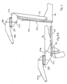
- an excavator arm with its basic boom 12 is connected in an articulated manner to a schematically shown excavator base 10, which can be rigidly attached to the rotatable superstructure of a mobile excavator similar to FIG. 6.
- the basic boom 12 articulated on the base 10 can be pivoted vertically by means of the cylinder 24.
- An intermediate boom 14 is articulated to the front end of the basic boom 12 and comprises a front part 14a, a rear part 14b and a common swivel joint 20, the axis of rotation 22 running in or parallel to the vertical pivoting plane of the basic boom 12 and rear part 14b.
- a dipper arm 16 for a bucket 18 or another digging tool is articulated on the front part 14a of the intermediate boom, which can be pivoted by means of a cylinder 28 supported on the intermediate boom 14, while a drive cylinder 30 is provided on the dipper arm for the working movements of the digging tool 18.
- the extended length of the intermediate boom 14 used in normal work is shown in solid lines in FIG. 1, while a space-saving transport position achieved while maintaining the upright base boom 12 is shown with broken lines, in which the front part 14a about the axis 22 of the swivel joint opposite the stretched position is rotated by 180 °. Under the conditions shown, in which the front part and the rear part cover each other, the intermediate boom 14 is in its shortest state, which can be used for the space-saving road transport position of the excavator arm, for example if it is arranged next to the driver's cab of a work vehicle.
- a swivel joint designed as a rotating ring 32 between the front part and the rear part of the intermediate bracket 14 is formed according to FIG. 3 between the mutually opposite connection surfaces 50, 52 on the front part 14a and on the rear part 14b in that a bearing ring 54 on the upper connection surface 50 and on the lower one Pad 52 a bearing ring 56 is attached, which are connected to each other via balls or similar rolling elements 55.
- the bearing rings 54, 56 are fastened to the connection surfaces with the aid of screws and with the aid of Sealing sleeves 68 sealed against each other.
- the upper bearing ring 54 has an internal toothing 58, in which a pinion 60 of the hydraulic rotary motor 36 engages in order to rotate the front part 14a with respect to the rear part 14b of the intermediate boom.
- a rotary union 70 for the hydraulic supply to the cylinders 28 and 30 is fastened to the upper connecting surface 50 and projects through an opening in the lower connecting surface 52.
- the rotary motor 36 and an actuating cylinder 62 for an index bolt 34 are flanged to the lower connecting surface.
- a piston 64 connected to the index bolt 34 is displaceable in the cylinder 62.
- the index bolt 34 is biased by a spring 72 into the locking position shown in solid lines, from which it is retracted by means of the hydraulic system against the spring force when the front part 14a of the intermediate boom is to be rotated.
- a sequence of positioning openings 66 (not shown) in the upper connecting surface 50 is assigned to the index bolt 34.
- the hydraulic circuit ensures that pressure medium is first supplied to the cylinder 62 so that the index bolt moves back and the connecting surface 50 is released for rotation.
- the pump 48 supplies the changeover valve 46 in the parallel circuit 42 with pressure medium from one or the opposite side.
- FIG. 4 and 4a show the excavator arm in similar working positions as in Fig. 1 and 2, but with the difference that the cylinder 26 of the intermediate boom is replaced by a link 38 which runs parallel to the base boom 12 and is connected to the base 10 .
- the rear part 14b of the intermediate boom is consequently constantly guided in parallel, so that it also rotates the axis of rotation 22 vertically in the position shown in FIG. 4a holds.
- FIG. 4 a it is indicated in FIG. 4 a that the link 38 from FIG. 4 - which can be provided twice in a symmetrical arrangement - is replaced by a hydraulic cylinder 40.
- the cylinder 40 acts like the handlebar 38, since it then has the same length as this.
- the resulting position of the axis of rotation 22 when the cylinder 40 is retracted is indicated by broken lines in FIG. 4a.
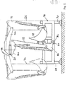
- FIGS. 5 and 5a A practical application example for the excavator arm which can be folded into a narrow space is shown in FIGS. 5 and 5a, where, for example, a rear frame 76 which can be attached to a vehicle is the carrier of an excavator arm according to the invention.
- a vertical pivot axis 84 for a mounting bracket 86 is arranged on bearing attachments 80, 82, which, like an excavator base, supports the lower end of the basic boom 12 and the associated pivot cylinder in an articulated manner.
- the mounting bracket 86 can be pivoted with the excavator arm from the straight line position indicated in FIG.
- the vertical pivot axis 84 remains in the center of the rear frame 76.
- FIG. 6 and 7 illustrate the use of the excavator arm in connection with an excavator base 10, which belongs to an uppercarriage 92 which can be rotated about a vertical axis 88 on the chassis 90 of a mobile excavator.
- the fixed base 10 projects forward into the preferred main excavator position indicated in FIG. 7.
- the excavator arm can be pivoted endlessly about the vertical axis 88, the front part 14a of the intermediate boom 14 with dipper stick and digging tool being able to be adjusted in any position of the uppercarriage parallel to the longitudinal direction of the vehicle or else in any position.
- the preferred transport position is reached according to FIG.
Landscapes
- Engineering & Computer Science (AREA)
- Mechanical Engineering (AREA)
- Mining & Mineral Resources (AREA)
- Civil Engineering (AREA)
- General Engineering & Computer Science (AREA)
- Structural Engineering (AREA)
- Shovels (AREA)
- Operation Control Of Excavators (AREA)
- Earth Drilling (AREA)
- Superconductors And Manufacturing Methods Therefor (AREA)
Priority Applications (1)
| Application Number | Priority Date | Filing Date | Title |
|---|---|---|---|
| AT89123435T ATE77669T1 (de) | 1988-12-24 | 1989-12-19 | Baggerarm. |
Applications Claiming Priority (2)
| Application Number | Priority Date | Filing Date | Title |
|---|---|---|---|
| DE3843753A DE3843753A1 (de) | 1988-12-24 | 1988-12-24 | Baggerarm |
| DE3843753 | 1988-12-24 |
Publications (2)
| Publication Number | Publication Date |
|---|---|
| EP0376120A1 true EP0376120A1 (fr) | 1990-07-04 |
| EP0376120B1 EP0376120B1 (fr) | 1992-06-24 |
Family
ID=6370155
Family Applications (1)
| Application Number | Title | Priority Date | Filing Date |
|---|---|---|---|
| EP89123435A Expired - Lifetime EP0376120B1 (fr) | 1988-12-24 | 1989-12-19 | Flèche pour excavatrice |
Country Status (4)
| Country | Link |
|---|---|
| US (1) | US5054990A (fr) |
| EP (1) | EP0376120B1 (fr) |
| AT (1) | ATE77669T1 (fr) |
| DE (2) | DE3843753A1 (fr) |
Cited By (1)
| Publication number | Priority date | Publication date | Assignee | Title |
|---|---|---|---|---|
| WO1996036775A1 (fr) * | 1995-05-19 | 1996-11-21 | Wolfgang Schmidt | Bras pour pelle excavatrice |
Families Citing this family (26)
| Publication number | Priority date | Publication date | Assignee | Title |
|---|---|---|---|---|
| US5195863A (en) * | 1982-09-08 | 1993-03-23 | Pingon Pierre J De | Excavator loader |
| DE4133505A1 (de) | 1990-11-15 | 1992-05-21 | Juergen Kulle | Vorrichtung zur fuehrung wenigstens eines werkzeugs |
| US5402898A (en) * | 1992-07-21 | 1995-04-04 | Jlg Industries, Inc. | Crane having boom rest |
| US5486084A (en) * | 1993-06-07 | 1996-01-23 | Raymond F. Pitman | Multiple purpose material handling and working apparatus |
| FR2733525B1 (fr) * | 1995-04-25 | 1997-07-04 | Mecalac | Engin de travaux publics dont l'outil de travail est monte a l'extremite d'un bras articule |
| US6163988A (en) * | 1995-05-17 | 2000-12-26 | Rockland, Inc. | Assembly connectable to an operating arm of a machine for performing work functions |
| US6581308B1 (en) | 2000-07-25 | 2003-06-24 | Caterpillar Inc. | High capacity bucket arrangement |
| US6401368B1 (en) | 2001-01-25 | 2002-06-11 | Mcleod James A. | Method and apparatus for excavating a trench |
| AUPR746101A0 (en) * | 2001-09-04 | 2001-09-27 | O'brien, Gerard | Excavator assembly |
| NL1019918C2 (nl) * | 2002-02-07 | 2003-08-21 | Dingenis Laurens Huissoon | Mobiele inrichting voor grondverzet en andere werkzaamheden, zoals het heffen en verplaatsen van lasten. |
| DE10321070B3 (de) * | 2003-05-10 | 2004-11-04 | O & K Orenstein & Koppel Gmbh | Geteilter Auslegearm für Bagger |
| EP1668194A2 (fr) * | 2003-10-03 | 2006-06-14 | The Charles Machine Works Inc | Machine de travaux a fonctions multiples |
| GB2417478A (en) * | 2004-08-27 | 2006-03-01 | Cole Technology Ltd | A boom assembly for an excavation vehicle |
| ITMI20042109A1 (it) * | 2004-11-04 | 2005-02-04 | Fiat Kobelco Construction Mach | Dispositivo e metodo per la frenatura di bracci portanti di una macchina di movimento terra ad esempio escavatore e macchina dotata di detto dispositivo |
| US8814142B2 (en) * | 2008-01-18 | 2014-08-26 | Res-Q-Jack, Inc. | Adjustable lifting and stabilization rescue strut system with improved jack and strut engagement means |
| USD629019S1 (en) * | 2009-09-17 | 2010-12-14 | J.C. Bamford Excavators Limited | Excavator arm |
| USD628604S1 (en) * | 2009-09-17 | 2010-12-07 | J.C. Bamford Excavators Limited | Loader arms |
| USD646302S1 (en) * | 2010-05-28 | 2011-10-04 | Deere & Comapny | Loader boom knee casting |
| USD654514S1 (en) * | 2010-05-28 | 2012-02-21 | Deere & Company | Loader boom foot casting |
| USD646303S1 (en) * | 2010-05-28 | 2011-10-04 | Deere & Company | Loader boom end cap casting |
| USD678919S1 (en) * | 2011-02-23 | 2013-03-26 | Cnh America Llc | Equipment dipperstick |
| USD646306S1 (en) * | 2011-02-23 | 2011-10-04 | Cnh America Llc | Equipment boom |
| USD671147S1 (en) * | 2011-07-29 | 2012-11-20 | Kobelko Construction Machinery Co., Ltd. | Boom for construction machine |
| USD672791S1 (en) * | 2011-07-29 | 2012-12-18 | Kobelko Construction Machinery Co., Ltd. | Boom for construction machine |
| EP2725183B1 (fr) * | 2012-10-24 | 2020-03-25 | Sandvik Mining and Construction Oy | Véhicule d'exploitation minière et procédé de déplacement de la flèche |
| CN103469833A (zh) * | 2013-09-26 | 2013-12-25 | 镇江金天辰新材料有限公司 | 一种轮式装载机工作装置 |
Citations (5)
| Publication number | Priority date | Publication date | Assignee | Title |
|---|---|---|---|---|
| FR1603020A (fr) * | 1968-05-20 | 1971-03-15 | ||
| DE1634704A1 (de) * | 1964-08-19 | 1971-11-18 | Bamford Excavators Ltd | Bagger |
| US4077140A (en) * | 1976-03-31 | 1978-03-07 | Societa Italiana Macchine Industriali Torino, S.P.A. | Hydraulic excavator equipment for excavation laterally of the excavator |
| GB2086347A (en) * | 1980-11-04 | 1982-05-12 | Vema Spa | Articulated arm for excavator machines |
| DE3234019A1 (de) * | 1982-09-14 | 1984-03-15 | O & K Orenstein & Koppel Ag, 1000 Berlin | Hydraulikbaggerausruestung |
Family Cites Families (12)
| Publication number | Priority date | Publication date | Assignee | Title |
|---|---|---|---|---|
| FR1330869A (fr) * | 1962-05-17 | 1963-06-28 | Poclain Atel | Perfectionnements aux pelles hydrauliques notamment aux pelles destinées à travailler en déporté |
| DE1875988U (de) * | 1963-05-02 | 1963-07-18 | Friedrich Wilh Schwing | Bagger. |
| US3283928A (en) * | 1965-06-17 | 1966-11-08 | Bosredon Pierre De | Lateral offset mounting for power shovel dipper arm |
| US3463336A (en) * | 1967-11-15 | 1969-08-26 | Bucyrus Erie Co | Backhoe excavator or the like with power actuated side tilting handle |
| FR2226353B1 (fr) * | 1973-04-18 | 1977-02-04 | Poclain Sa | |
| US4029225A (en) * | 1976-04-16 | 1977-06-14 | Caterpillar Tractor Co. | Boom-stick adapter for two-piece boom |
| US4394913A (en) * | 1980-11-07 | 1983-07-26 | Harnischfeger Corporation | Crane having power operated outriggers and lock means therefor |
| DE3146695A1 (de) * | 1981-11-25 | 1983-07-07 | Heinz Thumm Ölhydraulische Antriebe GmbH, 7012 Fellbach | Hydromotor, insbesondere fuer greiferdreheinrichtung an baggern oder kraenen |
| CA1195661A (fr) * | 1982-07-22 | 1985-10-22 | Yokichi Nagasawa | Engin de terrassement |
| DE3461666D1 (en) * | 1983-02-12 | 1987-01-22 | Hikoma Seisakusho Kk | Earth-working machine |
| DE8320291U1 (de) * | 1983-07-14 | 1985-05-15 | Karl Schaeff GmbH & Co, Maschinenfabrik, 7183 Langenburg | Fahrbarer hydraulischer loeffelbagger |
| DE3602213A1 (de) * | 1986-01-25 | 1987-07-30 | Hugo Dipl Ing Cordes | Mehrzweckeinrichtung fuer hydraulikbagger und krane |
-
1988
- 1988-12-24 DE DE3843753A patent/DE3843753A1/de active Granted
-
1989
- 1989-12-18 US US07/450,307 patent/US5054990A/en not_active Expired - Fee Related
- 1989-12-19 AT AT89123435T patent/ATE77669T1/de not_active IP Right Cessation
- 1989-12-19 DE DE8989123435T patent/DE58901747D1/de not_active Expired - Fee Related
- 1989-12-19 EP EP89123435A patent/EP0376120B1/fr not_active Expired - Lifetime
Patent Citations (5)
| Publication number | Priority date | Publication date | Assignee | Title |
|---|---|---|---|---|
| DE1634704A1 (de) * | 1964-08-19 | 1971-11-18 | Bamford Excavators Ltd | Bagger |
| FR1603020A (fr) * | 1968-05-20 | 1971-03-15 | ||
| US4077140A (en) * | 1976-03-31 | 1978-03-07 | Societa Italiana Macchine Industriali Torino, S.P.A. | Hydraulic excavator equipment for excavation laterally of the excavator |
| GB2086347A (en) * | 1980-11-04 | 1982-05-12 | Vema Spa | Articulated arm for excavator machines |
| DE3234019A1 (de) * | 1982-09-14 | 1984-03-15 | O & K Orenstein & Koppel Ag, 1000 Berlin | Hydraulikbaggerausruestung |
Cited By (1)
| Publication number | Priority date | Publication date | Assignee | Title |
|---|---|---|---|---|
| WO1996036775A1 (fr) * | 1995-05-19 | 1996-11-21 | Wolfgang Schmidt | Bras pour pelle excavatrice |
Also Published As
| Publication number | Publication date |
|---|---|
| DE3843753C2 (fr) | 1992-10-29 |
| DE58901747D1 (de) | 1992-07-30 |
| ATE77669T1 (de) | 1992-07-15 |
| US5054990A (en) | 1991-10-08 |
| EP0376120B1 (fr) | 1992-06-24 |
| DE3843753A1 (de) | 1990-06-28 |
Similar Documents
| Publication | Publication Date | Title |
|---|---|---|
| EP0376120B1 (fr) | Flèche pour excavatrice | |
| DE2641645A1 (de) | Abstuetzvorrichtung fuer fahrzeuge, die einen geraeteaufbau zur durchfuehrung von verlade- und erdbewegungsarbeiten oder anderer arbeitseinsaetze tragen | |
| DE2433919A1 (de) | Baumaschine | |
| DE3140686A1 (de) | "hydraulischer bagger" | |
| EP1408163A2 (fr) | Engin de travaux public et procédé pour l'opération d'un tel engin | |
| DE3425838A1 (de) | Loeffelbagger | |
| EP0625614A2 (fr) | Engin de chantier polyvalent | |
| DE2757968C2 (de) | Fahrbarer Löffelbagger | |
| EP0176829A1 (fr) | Excavateur compact | |
| DE1634994C3 (de) | Fahrbarer Löffelbagger | |
| EP0065118A2 (fr) | Excavatrice | |
| DE3932555C2 (fr) | ||
| DE2558799C3 (de) | Fahrbarer hydraulischer Löffelbagger | |
| DE2013849A1 (de) | Anbaubagger | |
| DE4229459A1 (de) | Baufahrzeug | |
| EP0440895B1 (fr) | Engin de terrassement, notamment une pelleteuse | |
| DE4006860C2 (fr) | ||
| DE2612879C2 (de) | Fahrbarer Löffelbagger | |
| DE3227136A1 (de) | Lade- und baggergeraet | |
| DE2012731C3 (de) | Tieflöffel-Anbaubagger | |
| DE202008015729U1 (de) | Abstützung für Mobilbagger | |
| DE4219720A1 (de) | Senkvorrichtung zum Einsatz in untertägigen Strecken | |
| EP4632154A1 (fr) | Machine de travail mobile avec bras pivotant | |
| AT386437B (de) | Zusatzvorrichtung fuer ein frontladegeraet | |
| DE69514339T2 (de) | Baggerlader |
Legal Events
| Date | Code | Title | Description |
|---|---|---|---|
| PUAI | Public reference made under article 153(3) epc to a published international application that has entered the european phase |
Free format text: ORIGINAL CODE: 0009012 |
|
| AK | Designated contracting states |
Kind code of ref document: A1 Designated state(s): AT BE DE ES FR GB IT NL SE |
|
| 17P | Request for examination filed |
Effective date: 19901114 |
|
| 17Q | First examination report despatched |
Effective date: 19910214 |
|
| GRAA | (expected) grant |
Free format text: ORIGINAL CODE: 0009210 |
|
| AK | Designated contracting states |
Kind code of ref document: B1 Designated state(s): AT BE DE ES FR GB IT NL SE |
|
| PG25 | Lapsed in a contracting state [announced via postgrant information from national office to epo] |
Ref country code: IT Free format text: LAPSE BECAUSE OF FAILURE TO SUBMIT A TRANSLATION OF THE DESCRIPTION OR TO PAY THE FEE WITHIN THE PRE;WARNING: LAPSES OF ITALIAN PATENTS WITH EFFECTIVE DATE BEFORE 2007 MAY HAVE OCCURRED AT ANY TIME BEFORE 2007. THE CORRECT EFFECTIVE DATE MAY BE DIFFERENT FROM THE ONE RECORDED.SCRIBED TIME-LIMIT Effective date: 19920624 Ref country code: BE Effective date: 19920624 Ref country code: ES Free format text: THE PATENT HAS BEEN ANNULLED BY A DECISION OF A NATIONAL AUTHORITY Effective date: 19920624 Ref country code: NL Effective date: 19920624 Ref country code: SE Effective date: 19920624 Ref country code: FR Effective date: 19920624 Ref country code: GB Effective date: 19920624 |
|
| REF | Corresponds to: |
Ref document number: 77669 Country of ref document: AT Date of ref document: 19920715 Kind code of ref document: T |
|
| REF | Corresponds to: |
Ref document number: 58901747 Country of ref document: DE Date of ref document: 19920730 |
|
| EN | Fr: translation not filed | ||
| NLV1 | Nl: lapsed or annulled due to failure to fulfill the requirements of art. 29p and 29m of the patents act | ||
| PG25 | Lapsed in a contracting state [announced via postgrant information from national office to epo] |
Ref country code: AT Effective date: 19921219 |
|
| GBV | Gb: ep patent (uk) treated as always having been void in accordance with gb section 77(7)/1977 [no translation filed] |
Effective date: 19920624 |
|
| PLBE | No opposition filed within time limit |
Free format text: ORIGINAL CODE: 0009261 |
|
| STAA | Information on the status of an ep patent application or granted ep patent |
Free format text: STATUS: NO OPPOSITION FILED WITHIN TIME LIMIT |
|
| 26N | No opposition filed | ||
| PGFP | Annual fee paid to national office [announced via postgrant information from national office to epo] |
Ref country code: DE Payment date: 19990224 Year of fee payment: 10 |
|
| PG25 | Lapsed in a contracting state [announced via postgrant information from national office to epo] |
Ref country code: DE Free format text: LAPSE BECAUSE OF NON-PAYMENT OF DUE FEES Effective date: 20001003 |