EP0376644A1 - Radiale Strömungsmaschine - Google Patents
Radiale Strömungsmaschine Download PDFInfo
- Publication number
- EP0376644A1 EP0376644A1 EP89313507A EP89313507A EP0376644A1 EP 0376644 A1 EP0376644 A1 EP 0376644A1 EP 89313507 A EP89313507 A EP 89313507A EP 89313507 A EP89313507 A EP 89313507A EP 0376644 A1 EP0376644 A1 EP 0376644A1
- Authority
- EP
- European Patent Office
- Prior art keywords
- rotor
- shaft
- housing
- module according
- radial
- Prior art date
- Legal status (The legal status is an assumption and is not a legal conclusion. Google has not performed a legal analysis and makes no representation as to the accuracy of the status listed.)
- Granted
Links
- 239000012530 fluid Substances 0.000 title claims abstract description 70
- 238000004891 communication Methods 0.000 claims description 8
- 238000007789 sealing Methods 0.000 claims description 7
- 125000006850 spacer group Chemical group 0.000 claims description 7
- 238000000034 method Methods 0.000 claims description 2
- 230000007246 mechanism Effects 0.000 abstract description 23
- 230000017525 heat dissipation Effects 0.000 abstract description 3
- 238000005381 potential energy Methods 0.000 abstract description 3
- 238000010276 construction Methods 0.000 description 6
- 238000012864 cross contamination Methods 0.000 description 1
- 238000004519 manufacturing process Methods 0.000 description 1
Images

Classifications
-
- F—MECHANICAL ENGINEERING; LIGHTING; HEATING; WEAPONS; BLASTING
- F01—MACHINES OR ENGINES IN GENERAL; ENGINE PLANTS IN GENERAL; STEAM ENGINES
- F01D—NON-POSITIVE DISPLACEMENT MACHINES OR ENGINES, e.g. STEAM TURBINES
- F01D1/00—Non-positive-displacement machines or engines, e.g. steam turbines
- F01D1/02—Non-positive-displacement machines or engines, e.g. steam turbines with stationary working-fluid guiding means and bladed or like rotor, e.g. multi-bladed impulse steam turbines
- F01D1/06—Non-positive-displacement machines or engines, e.g. steam turbines with stationary working-fluid guiding means and bladed or like rotor, e.g. multi-bladed impulse steam turbines traversed by the working-fluid substantially radially
Definitions
- This invention relates to a radial flow fluid pressure module and more particularly to a module which can be used in radial flow turbomachinery such as a centripetal turbine motor or a centrifugal fluid pressurizer.
- Turbomachinery refers to fluid pressure mechanisms for producing pressure or power whose primary elements are rotative as opposed to reciprocating.
- a turbine motor is a fluid pressure mechanism whose rotor is driven by a pressurized motive fluid to produce a rotary mechanical output.
- a rotary fluid pressurizer such as a centrifugal compressor, pump, blower, or fan is a fluid pressure mechanism whose rotor is driven by an external power source to increase the potential energy of a working fluid.
- a fluid pressure mechanism can refer to either a turbine motor or a fluid pressurizer.
- a rotary pressure mechanism can have many different flow configurations.
- the fluid flows axially through radially extending blades on the rotor element.
- the fluid flows substantially radially through axially extending blades on one side of the rotor element.
- the fluid flows radially on both sides of the rotor element through axially extending blades.
- the fluid flow can be radially inward or radially outward.
- all of the above pressure mechanisms can have single or multiple stages of blades.
- a two-faced radial flow configuration has advantages over the alternative configurations. For example, radial loads can be inherently balanced. Additionally, the axial thrust loads on the rotor and shaft can be minimized since the fluid loading on the opposed faces of the rotor is balanced. Finally, a two-faced rotor allows a compact package for a desired fluid pressure or power output.
- centripetal turbine motor and a centrifugal fluid pressurizer differ in operation only in that the fluid flow is radially opposite.
- known two-faced centripetal turbine motors and centrifugal fluid pressurizers differ substantially in construction. Many similarly functioning parts are unnecessarily constructed differently for the different modes of operation.
- the orientation of the mechanism determines the direction of the shaft rotation.
- a differently constructed mechanism is required to provide shaft rotation in the reverse direction.
- the power takeoff/drive connection is limited to one side of the mechanism.
- Major reconstruction or a differently constructed unit is required to reverse the side of the power takeoff or the power drive connection.
- a seal is needed to separate the working or motive fluid areas from the lubricated areas to prevent cross contamination.
- a seal that is located at an interface having a large pressure differential requires a more complex and thus more expensive construction. Also high pressure seals may produce more unwanted frictional heat.
- bearings are located in a position from which it is difficult to dissipate heat, more durable and expensive bearings are required.
- the present invention provides several advantages over known fluid pressure mechanism construction and overcomes various disadvantages of presently known fluid pressure mechanisms.
- the assembled module can be orientated for shaft rotation in either direction.
- the assembled module can have power take-off or power connection to either side.
- a radial flow mechanism having a symmetric housing assembly defining a hollow rotor chamber.
- a symmetric shaft and rotor assembly is supported for rotation in the rotor chamber.
- a plurality of radial flow paths are defined by the rotor and the housing assembly.
- the assembled module may be powered by a pressurized motive fluid that flows radially inward to rotate the rotor.
- the rotor may be driven by an external power source so that a working fluid increases in potential energy as it moves centrifugally outward.
- the assembled module is symmetric about the rotor member so that the rotor can be orientated for either direction of rotation and so that power takeoff/ drive connection can be to either side of the module.
- the fluid pressure mechanism is constructed so that the seals are located at an interface having a low pressure differential and the bearings are located adjacent an area encouraging heat dissipation.
- the present invention is related to commonly assigned Serial No. 07/291,183 titled “Radial Flow Rotor Assembly” and filed concurrently with this application and hereby incorporated by reference into this application.
- a fluid pressure module is a module having a rotor either rotated by a pressurized motive fluid to produce rotary mechanical output, such as a turbine motor, or a rotor driven by an external power source to produce high pressure, low velocity fluid such as in a centrifugal compressor or pump or high velocity, low pressure fluid, such as in a centrifugal fan or blower.
- the module 10 includes a symmetric housing assembly 12 which is composed of mateable right and left housing members 14 and 16.
- the housing members are mirror images of each other.
- the housing assembly is the primary stationary part of the module.
- a hollow rotor chamber 18 is formed on the interior of the housing assembly between the mated housing members.
- An opening 20 extends longitudinally through the center of the housing assembly.
- a rotor shaft 22 having one right hand and one left hand threaded end is supported for rotation in the longitudinal opening of the housing assembly by two suitable bearings 24.
- the bearings are mounted in integrally formed outer shoulder recesses 25 on the outside faces of each housing member.
- a rotor member 26 having a center bore is mounted on the shaft for rotation with the shaft in the rotor chamber.
- the rotor member has a thick hub portion 28 concentric with the center bore.
- a radially extending disc portion 30 has two opposed faces which smoothly converge to a thin outer tip surface 32.
- the thick hub portion allows more even stress distribution at the bore of the rotor.
- the rotor is typically press fit on the shaft.
- the tapered disk portion reduces the weight and mass at the outer circumferential surface of the rotor member where the tip speeds are the highest and the centrifugal forces are the greatest.
- a pair of annular seals 34 are mounted in integrally formed inner shoulder recesses 36 in the housing members to sealingly contact the rotor assembly.
- Bearing spacers 38 are press fit onto the shaft to abut the rotor.
- the stationary seals contact the outer circumferential surface of the rotating spacers 38 to provide a seal at a low pressure interface between the rotor assembly and housing.
- the rotating components are axially positioned and centered inside the housing assembly by use of an adjusting mechanism.
- Axially resilient spacing members 42 are positioned in the integrally formed outer shoulder recesses 25 between each housing member and each bearing 24.
- a retainer member such as an appropriately threaded nut 44 is threaded in position on one threaded end of the rotor shaft 22 so as to abut one bearing.
- a second retainer 45 such as an appropriately threaded power take-off/drive connection member is threaded onto the other end of the shaft so as to abut the second bearing and clamp the rotating components together.
- An exteriorly threaded adjusting nut 46 is then positioned in a threaded flange on the housing member.
- the shaft and rotor assembly including both bearings 24 and bearing spacers 38 can then be moved relative to the housing by the adjusting nut to axially center the rotor 26 in the rotor chamber.
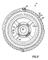
- the housing assembly 12 is constructed of two essentially mirror-image right and left hand housing members 14 and 16, one shown in Figure 2.
- the members are joined together by suitable means such as thru bolts at 48 to form the housing assembly in which the rotor member rotates.
- Outer radial openings 52 are provided circumferentially in each housing member for fluid communication between the exterior of the housing assembly and the rotor chamber.
- a first set of integrally formed nozzles 54 which axially extend from each housing member are positioned in the radial opening to divide the opening into individual nozzle openings 56.
- a circumferential spacing ring 58 having a thickness approximate to the thickness of the rotor tip 32 is positioned in the radial opening 52 between the housing members. The spacer ring 58 defines separate nozzle openings for each face of the rotor member.
- a pair of opposed axial passages 62 are also in fluid communication with the inner portion of the rotor chamber.
- the passages are annular and circumscribe the seals 34 and bearings 24.
- the inner annular surface 64 of the axial passage is supported by struts 65 from the outer annular surface 66.
- each housing member 14 and 16 has annular flanges 68 and 69 respectively which extend radially outward from the housing assembly.
- a cylindrical plenum member 70 extends circumferentially between the flanges. The plenum member is in circumferential sealing contact with both flanges and thus forms a plenum chamber 72 with the exterior of the housing members. The plenum chamber is in fluid communication with the radial openings 52. The plenum member also has appropriate openings to the exterior of the module.
- Axially extending from the opposed faces of the turbine disk portion 30 are a first circular row of turbine blades 74. These blades are arranged in a circular pattern on each face of the rotor member.
- the first row of blades 74 and the first set of nozzles 54 are arranged concentrically and are generally radially adjacent so as to be in radial fluid communication with each other.
- a second and successive sets of nozzles 76 may axially extend from each housing member into the rotor chamber.
- a second and successive circular rows of axially extending rotor blades 78 may be positioned on each face of the rotor member concentric with and radially inward from the first row of blades 74. All the blade rows and nozzle sets are concentric and are arranged alternatively with each other. Adjacent blade rows and nozzle sets have minimal radial clearances.
- the blade tips have minimal axial clearance with the sides of the rotor chamber 18 and the nozzle tips have minimal axial clearance with the faces of the rotor member.
- a plurality of radially directed flow paths are defined by the rotor blades and the nozzles of the housing members.
- a symmetric shaft and rotor assembly is provided as a subassembly.
- One suitable shaft and rotor assembly is that described in Serial No. 07/291,183 titled “Radial Flow Rotor Assembly” filed concurrently with this application and previously incorporated by reference in this application.
- the shaft and rotor assembly includes a shaft 22 having two threaded ends.
- a rotor member 26 is mounted or can be integrally formed on the center of the shaft.
- Bearing spacers 38 are also provided on the shaft and rotor assembly.
- the first step in assembling a module is to position an annular seal 34 in the integrally formed inside shoulder recess of each housing member.
- One housing member 14 and 16 is then positioned on each end of the rotor assembly shaft with the spacer ring 58 between them so that the rotor is enclosed in the rotor chamber.
- the ends of the shaft project through the seals 34 and protrude out the longitudinal opening 20 in each housing member.
- a resilient spacing member 42 and a bearing 24 is positioned on each protruding end of the shaft so as to fit within the integrally formed outer shoulder recess 25 of each housing member.
- the appropriately threaded retainers 44 and 45 are fixed on each end of the shaft so as to axially clamp the rotating components together.
- the adjusting nut 46 is then threaded into the housing member on an appropriate side so as to axially center the rotor assembly within the rotor chamber.
- the cylindrical plenum member 70 is sealingly positioned on the radially extending flanges 68 and 69 so as to form a plenum chamber 72.
- the fluid pressure module 10 will now be described in operation as a turbine motor.
- a pressurized motive fluid is introduced from a suitable source into the plenum chamber 72.
- the motive fluid flows generally radially through the first set of nozzles 54. These inlet nozzles turn the motive fluid to a more tangential direction to act on the first row of turbine blades 74.
- the motive fluid acts on the first stage of blades in an impulse manner.
- the motive fluid then enters the second set of nozzles 76 which also tangentially directs the fluid to the second row of blades 78.
- the motive fluid acts on the second stage of blades in an impulse manner. On exiting the second or final row of blades the motive fluid is smoothly turned to a more axial direction by the diverging power source.
- the fluid increases in pressure and/or velocity. As the working fluid continues to move radially outward through nozzles 76 and blades 74 of the flow paths, the fluid is further increased in pressure and/or velocity. When the fluid exits the nozzles 54 it is at a higher fluid pressure and/or fluid velocity than the ambient inlet air.
- the fluid pressure module 10 can be readily assembled without concern for the rotational direction of the shaft or the accessibility of the power take-off or drive connection. Since it is symmetric, the entire module can be turned 180 o for left hand or right hand shaft rotation. Additionally, a power take-off or drive connection can be connected to either the right or left side of the rotor shaft.
- outer shoulder recesses for the rotor shaft bearings and the inner shoulder recesses for the rotor shaft seals are integrally formed with the mateable housing members, precise radial centering of the rotor assembly within the rotor chamber is automatic. Precise axial centering is easily attained using the adjusting nut. This radically simplifies assembly of the module when compared to housings in which multicomponent housing shell halves are used.
Landscapes
- Engineering & Computer Science (AREA)
- Mechanical Engineering (AREA)
- General Engineering & Computer Science (AREA)
- Turbine Rotor Nozzle Sealing (AREA)
- Structures Of Non-Positive Displacement Pumps (AREA)
- Hydraulic Motors (AREA)
Applications Claiming Priority (2)
| Application Number | Priority Date | Filing Date | Title |
|---|---|---|---|
| US07/291,184 US4927323A (en) | 1988-12-28 | 1988-12-28 | Radial flow fluid pressure module |
| US291184 | 1988-12-28 |
Publications (2)
| Publication Number | Publication Date |
|---|---|
| EP0376644A1 true EP0376644A1 (de) | 1990-07-04 |
| EP0376644B1 EP0376644B1 (de) | 1993-09-15 |
Family
ID=23119244
Family Applications (1)
| Application Number | Title | Priority Date | Filing Date |
|---|---|---|---|
| EP89313507A Expired - Lifetime EP0376644B1 (de) | 1988-12-28 | 1989-12-22 | Radiale Strömungsmaschine |
Country Status (5)
| Country | Link |
|---|---|
| US (1) | US4927323A (de) |
| EP (1) | EP0376644B1 (de) |
| JP (1) | JPH02215902A (de) |
| CA (1) | CA2006667C (de) |
| DE (1) | DE68909199T2 (de) |
Cited By (2)
| Publication number | Priority date | Publication date | Assignee | Title |
|---|---|---|---|---|
| CN101324193B (zh) * | 2007-06-15 | 2011-01-19 | 程建平 | 径向双流式汽轮机 |
| CN102434218A (zh) * | 2011-11-27 | 2012-05-02 | 王政玉 | 一种流体涡轮发动机 |
Families Citing this family (7)
| Publication number | Priority date | Publication date | Assignee | Title |
|---|---|---|---|---|
| US6736610B2 (en) * | 1999-07-30 | 2004-05-18 | Cifarelli S.P.A. | Blower fan, in particular for blowing apparatuses, and blowing apparatus provided thereof |
| RU2177086C2 (ru) * | 1999-11-25 | 2001-12-20 | Лесковский Михаил Михайлович | Многоступенчатый насос |
| CN100374686C (zh) * | 2006-08-14 | 2008-03-12 | 吴法森 | 聚能脉冲式蒸汽轮机 |
| WO2017059495A1 (en) * | 2015-10-07 | 2017-04-13 | The University Of Queensland | A turbine |
| JP6648512B2 (ja) * | 2015-12-09 | 2020-02-14 | 日本精工株式会社 | スピンドル装置 |
| RU185496U1 (ru) * | 2018-01-18 | 2018-12-06 | Сергей Петрович Шипеленко | Двухступенчатое центробежное рабочее колесо с двухсторонним входом |
| RU209266U1 (ru) * | 2021-08-24 | 2022-02-10 | Акционерное общество "ГМС Ливгидромаш" | Многоступенчатый центробежный насос |
Citations (6)
| Publication number | Priority date | Publication date | Assignee | Title |
|---|---|---|---|---|
| DE207665C (de) * | ||||
| GB106751A (de) * | 1900-01-01 | |||
| FR355376A (fr) * | 1905-04-11 | 1905-10-30 | Francois Gouttes | Moteur spiral-rotatif à grande vitesse |
| FR522996A (fr) * | 1919-06-13 | 1921-08-09 | Leon Metais | Perfectionnements aux turbines radiales à vapeur ou à fluide sous pression |
| CH111193A (fr) * | 1924-07-23 | 1925-08-01 | Arthur Forman Alfred | Turbine à vapeur. |
| US2268929A (en) * | 1939-02-03 | 1942-01-06 | Dupont Emile | Compressor or the like |
Family Cites Families (12)
| Publication number | Priority date | Publication date | Assignee | Title |
|---|---|---|---|---|
| US715441A (en) * | 1901-05-31 | 1902-12-09 | William C Vandegrift | Fluid-pumping and fluid-actuated machine. |
| US773136A (en) * | 1903-03-10 | 1904-10-25 | Dudley Farrand | Elastic-fluid turbine. |
| US1158978A (en) * | 1909-03-01 | 1915-11-02 | Wilhelm Honegger | Turbine-pump, turbine-blower, and propeller. |
| US1017438A (en) * | 1911-02-28 | 1912-02-13 | Thomas Mcauley | Compound high-pressure turbine-wheel. |
| US2775208A (en) * | 1953-04-20 | 1956-12-25 | Pratt & Whitney Co Inc | Rotary pumps |
| FR1123261A (fr) * | 1955-03-05 | 1956-09-19 | Electricite De France | Perfectionnements aux turbines hydrauliques à injection partielle |
| US3334863A (en) * | 1964-11-06 | 1967-08-08 | Laval Turbine | Turbine |
| US3357361A (en) * | 1965-10-21 | 1967-12-12 | Bendix Corp | High velocity pump |
| US3457869A (en) * | 1967-02-13 | 1969-07-29 | Itt | Centrifugal pumps |
| US3892500A (en) * | 1974-07-10 | 1975-07-01 | Westinghouse Electric Corp | Adjustable axial positioning device |
| US4439096A (en) * | 1982-08-13 | 1984-03-27 | A. W. Chesterton Company | Impeller adjuster for centrifugal pump |
| US4563124A (en) * | 1984-02-24 | 1986-01-07 | Figgie International Inc. | Double suction, single stage volute pump |
-
1988
- 1988-12-28 US US07/291,184 patent/US4927323A/en not_active Expired - Lifetime
-
1989
- 1989-12-22 DE DE89313507T patent/DE68909199T2/de not_active Expired - Fee Related
- 1989-12-22 EP EP89313507A patent/EP0376644B1/de not_active Expired - Lifetime
- 1989-12-26 JP JP1335266A patent/JPH02215902A/ja active Pending
- 1989-12-27 CA CA002006667A patent/CA2006667C/en not_active Expired - Lifetime
Patent Citations (6)
| Publication number | Priority date | Publication date | Assignee | Title |
|---|---|---|---|---|
| DE207665C (de) * | ||||
| GB106751A (de) * | 1900-01-01 | |||
| FR355376A (fr) * | 1905-04-11 | 1905-10-30 | Francois Gouttes | Moteur spiral-rotatif à grande vitesse |
| FR522996A (fr) * | 1919-06-13 | 1921-08-09 | Leon Metais | Perfectionnements aux turbines radiales à vapeur ou à fluide sous pression |
| CH111193A (fr) * | 1924-07-23 | 1925-08-01 | Arthur Forman Alfred | Turbine à vapeur. |
| US2268929A (en) * | 1939-02-03 | 1942-01-06 | Dupont Emile | Compressor or the like |
Cited By (2)
| Publication number | Priority date | Publication date | Assignee | Title |
|---|---|---|---|---|
| CN101324193B (zh) * | 2007-06-15 | 2011-01-19 | 程建平 | 径向双流式汽轮机 |
| CN102434218A (zh) * | 2011-11-27 | 2012-05-02 | 王政玉 | 一种流体涡轮发动机 |
Also Published As
| Publication number | Publication date |
|---|---|
| US4927323A (en) | 1990-05-22 |
| DE68909199D1 (de) | 1993-10-21 |
| JPH02215902A (ja) | 1990-08-28 |
| DE68909199T2 (de) | 1994-04-21 |
| EP0376644B1 (de) | 1993-09-15 |
| CA2006667A1 (en) | 1990-06-28 |
| CA2006667C (en) | 1995-12-12 |
Similar Documents
| Publication | Publication Date | Title |
|---|---|---|
| US5224339A (en) | Counterflow single rotor turbojet and method | |
| US4882902A (en) | Turbine cooling air transferring apparatus | |
| US4455121A (en) | Rotating turbine stator | |
| US5281090A (en) | Thermally-tuned rotary labyrinth seal with active seal clearance control | |
| US4968216A (en) | Two-stage fluid driven turbine | |
| US5237817A (en) | Gas turbine engine having low cost speed reduction drive | |
| US5071312A (en) | Turbines | |
| GB2189845A (en) | Gas turbine cooling air transferring apparatus | |
| CA2489629A1 (en) | Methods and apparatus for machining components | |
| US4927323A (en) | Radial flow fluid pressure module | |
| US3964342A (en) | Turbine shaft balancing | |
| MXPA97003218A (en) | Subassemble of gas turbine that has a seal of escobi | |
| US4059972A (en) | Turbine shaft balancing | |
| EP1079067B1 (de) | Kühlluftzufuhrsystem für einen Rotor | |
| JP4667043B2 (ja) | 真空ポンプ排出装置 | |
| US2788951A (en) | Cooling of turbine rotors | |
| RU2377417C2 (ru) | Модуль турбины для газотурбинного двигателя с ротором, который включает в себя моноблок | |
| JPH10212901A (ja) | 軸流タービン機械 | |
| US5427499A (en) | Turbines having depressions in the working members thereof | |
| JPH01190995A (ja) | 閉じ込め組立体 | |
| EP1386060B1 (de) | Turbinen- oder kompressorvorrichtung und verfahren zur montage der vorrichtung | |
| US5176508A (en) | Turbopump system for driving a plurality of pumps | |
| EP0984136A1 (de) | Doppelseitige Zentrifugal- Zentripedalturbine | |
| GB2270543A (en) | Turbines. | |
| US12326089B2 (en) | Seal assembly for a gas turbine engine |
Legal Events
| Date | Code | Title | Description |
|---|---|---|---|
| PUAI | Public reference made under article 153(3) epc to a published international application that has entered the european phase |
Free format text: ORIGINAL CODE: 0009012 |
|
| AK | Designated contracting states |
Kind code of ref document: A1 Designated state(s): DE FR GB IT SE |
|
| 17P | Request for examination filed |
Effective date: 19901206 |
|
| 17Q | First examination report despatched |
Effective date: 19920304 |
|
| GRAA | (expected) grant |
Free format text: ORIGINAL CODE: 0009210 |
|
| AK | Designated contracting states |
Kind code of ref document: B1 Designated state(s): DE FR GB IT SE |
|
| REF | Corresponds to: |
Ref document number: 68909199 Country of ref document: DE Date of ref document: 19931021 |
|
| ITF | It: translation for a ep patent filed | ||
| ET | Fr: translation filed | ||
| PLBE | No opposition filed within time limit |
Free format text: ORIGINAL CODE: 0009261 |
|
| STAA | Information on the status of an ep patent application or granted ep patent |
Free format text: STATUS: NO OPPOSITION FILED WITHIN TIME LIMIT |
|
| 26N | No opposition filed | ||
| EAL | Se: european patent in force in sweden |
Ref document number: 89313507.9 |
|
| REG | Reference to a national code |
Ref country code: GB Ref legal event code: IF02 |
|
| PGFP | Annual fee paid to national office [announced via postgrant information from national office to epo] |
Ref country code: GB Payment date: 20071227 Year of fee payment: 19 |
|
| PGFP | Annual fee paid to national office [announced via postgrant information from national office to epo] |
Ref country code: SE Payment date: 20071227 Year of fee payment: 19 Ref country code: DE Payment date: 20080131 Year of fee payment: 19 Ref country code: IT Payment date: 20071229 Year of fee payment: 19 |
|
| PGFP | Annual fee paid to national office [announced via postgrant information from national office to epo] |
Ref country code: FR Payment date: 20071217 Year of fee payment: 19 |
|
| EUG | Se: european patent has lapsed | ||
| GBPC | Gb: european patent ceased through non-payment of renewal fee |
Effective date: 20081222 |
|
| REG | Reference to a national code |
Ref country code: FR Ref legal event code: ST Effective date: 20090831 |
|
| PG25 | Lapsed in a contracting state [announced via postgrant information from national office to epo] |
Ref country code: DE Free format text: LAPSE BECAUSE OF NON-PAYMENT OF DUE FEES Effective date: 20090701 |
|
| PG25 | Lapsed in a contracting state [announced via postgrant information from national office to epo] |
Ref country code: GB Free format text: LAPSE BECAUSE OF NON-PAYMENT OF DUE FEES Effective date: 20081222 |
|
| PG25 | Lapsed in a contracting state [announced via postgrant information from national office to epo] |
Ref country code: FR Free format text: LAPSE BECAUSE OF NON-PAYMENT OF DUE FEES Effective date: 20081231 |
|
| PG25 | Lapsed in a contracting state [announced via postgrant information from national office to epo] |
Ref country code: SE Free format text: LAPSE BECAUSE OF NON-PAYMENT OF DUE FEES Effective date: 20081223 |
|
| PG25 | Lapsed in a contracting state [announced via postgrant information from national office to epo] |
Ref country code: IT Free format text: LAPSE BECAUSE OF NON-PAYMENT OF DUE FEES Effective date: 20081222 |