EP0378627B1 - Procede et dispositif de controle des defauts de fonctionnement pour le reglage du ralenti - Google Patents
Procede et dispositif de controle des defauts de fonctionnement pour le reglage du ralenti Download PDFInfo
- Publication number
- EP0378627B1 EP0378627B1 EP89907085A EP89907085A EP0378627B1 EP 0378627 B1 EP0378627 B1 EP 0378627B1 EP 89907085 A EP89907085 A EP 89907085A EP 89907085 A EP89907085 A EP 89907085A EP 0378627 B1 EP0378627 B1 EP 0378627B1
- Authority
- EP
- European Patent Office
- Prior art keywords
- angle
- throttle valve
- servomotor
- test
- idling
- Prior art date
- Legal status (The legal status is an assumption and is not a legal conclusion. Google has not performed a legal analysis and makes no representation as to the accuracy of the status listed.)
- Expired - Lifetime
Links
- 238000000034 method Methods 0.000 title claims abstract description 36
- 238000012360 testing method Methods 0.000 claims abstract description 74
- 238000002485 combustion reaction Methods 0.000 claims abstract description 13
- 230000008859 change Effects 0.000 claims description 9
- 238000011156 evaluation Methods 0.000 claims description 6
- 239000000446 fuel Substances 0.000 claims description 5
- 230000007257 malfunction Effects 0.000 claims description 5
- 238000005259 measurement Methods 0.000 claims description 2
- 238000012937 correction Methods 0.000 claims 1
- 230000002950 deficient Effects 0.000 abstract 1
- 230000006870 function Effects 0.000 description 6
- 238000003745 diagnosis Methods 0.000 description 4
- 238000001514 detection method Methods 0.000 description 3
- 238000012544 monitoring process Methods 0.000 description 3
- 230000006399 behavior Effects 0.000 description 2
- 238000011161 development Methods 0.000 description 2
- 238000010586 diagram Methods 0.000 description 2
- 238000010998 test method Methods 0.000 description 2
- 230000007547 defect Effects 0.000 description 1
- 230000004069 differentiation Effects 0.000 description 1
- 238000002347 injection Methods 0.000 description 1
- 239000007924 injection Substances 0.000 description 1
- 238000011835 investigation Methods 0.000 description 1
- 230000008569 process Effects 0.000 description 1
- 230000000717 retained effect Effects 0.000 description 1
- 230000008961 swelling Effects 0.000 description 1
- 230000001960 triggered effect Effects 0.000 description 1
Images

Classifications
-
- F—MECHANICAL ENGINEERING; LIGHTING; HEATING; WEAPONS; BLASTING
- F02—COMBUSTION ENGINES; HOT-GAS OR COMBUSTION-PRODUCT ENGINE PLANTS
- F02D—CONTROLLING COMBUSTION ENGINES
- F02D41/00—Electrical control of supply of combustible mixture or its constituents
- F02D41/22—Safety or indicating devices for abnormal conditions
-
- F—MECHANICAL ENGINEERING; LIGHTING; HEATING; WEAPONS; BLASTING
- F02—COMBUSTION ENGINES; HOT-GAS OR COMBUSTION-PRODUCT ENGINE PLANTS
- F02D—CONTROLLING COMBUSTION ENGINES
- F02D11/00—Arrangements for, or adaptations to, non-automatic engine control initiation means, e.g. operator initiated
- F02D11/06—Arrangements for, or adaptations to, non-automatic engine control initiation means, e.g. operator initiated characterised by non-mechanical control linkages, e.g. fluid control linkages or by control linkages with power drive or assistance
- F02D11/10—Arrangements for, or adaptations to, non-automatic engine control initiation means, e.g. operator initiated characterised by non-mechanical control linkages, e.g. fluid control linkages or by control linkages with power drive or assistance of the electric type
- F02D11/107—Safety-related aspects
-
- F—MECHANICAL ENGINEERING; LIGHTING; HEATING; WEAPONS; BLASTING
- F02—COMBUSTION ENGINES; HOT-GAS OR COMBUSTION-PRODUCT ENGINE PLANTS
- F02D—CONTROLLING COMBUSTION ENGINES
- F02D31/00—Use of speed-sensing governors to control combustion engines, not otherwise provided for
- F02D31/001—Electric control of rotation speed
- F02D31/002—Electric control of rotation speed controlling air supply
- F02D31/003—Electric control of rotation speed controlling air supply for idle speed control
- F02D31/004—Electric control of rotation speed controlling air supply for idle speed control by controlling a throttle stop
-
- F—MECHANICAL ENGINEERING; LIGHTING; HEATING; WEAPONS; BLASTING
- F02—COMBUSTION ENGINES; HOT-GAS OR COMBUSTION-PRODUCT ENGINE PLANTS
- F02D—CONTROLLING COMBUSTION ENGINES
- F02D41/00—Electrical control of supply of combustible mixture or its constituents
- F02D41/22—Safety or indicating devices for abnormal conditions
- F02D41/221—Safety or indicating devices for abnormal conditions relating to the failure of actuators or electrically driven elements
-
- F—MECHANICAL ENGINEERING; LIGHTING; HEATING; WEAPONS; BLASTING
- F02—COMBUSTION ENGINES; HOT-GAS OR COMBUSTION-PRODUCT ENGINE PLANTS
- F02D—CONTROLLING COMBUSTION ENGINES
- F02D45/00—Electrical control not provided for in groups F02D41/00 - F02D43/00
-
- Y—GENERAL TAGGING OF NEW TECHNOLOGICAL DEVELOPMENTS; GENERAL TAGGING OF CROSS-SECTIONAL TECHNOLOGIES SPANNING OVER SEVERAL SECTIONS OF THE IPC; TECHNICAL SUBJECTS COVERED BY FORMER USPC CROSS-REFERENCE ART COLLECTIONS [XRACs] AND DIGESTS
- Y02—TECHNOLOGIES OR APPLICATIONS FOR MITIGATION OR ADAPTATION AGAINST CLIMATE CHANGE
- Y02T—CLIMATE CHANGE MITIGATION TECHNOLOGIES RELATED TO TRANSPORTATION
- Y02T10/00—Road transport of goods or passengers
- Y02T10/10—Internal combustion engine [ICE] based vehicles
- Y02T10/40—Engine management systems
Definitions
- the invention relates to a method and a device for checking the malfunction of an idle control arrangement for an internal combustion engine.
- the idle control arrangement in series according to the attached FIG. 1 has a throttle valve 10, which is adjustable with the aid of an adjustment cable 11 or a servomotor 12.
- the setting angle ALPHA of the throttle valve 10 is determined from the voltage which is tapped at potentiometer connections 13 by a potentiometer which is connected to the axis of rotation of the throttle valve 10.
- the servomotor 12 has an actuating housing 14 in which an actuating shaft 15 is arranged such that it can be pushed back and forth.
- an actuating shaft 15 In the actuating shaft 15 itself a reciprocating part is also arranged, namely an idle contact pin 16.
- the free end of this contact pin 16 presses in the position shown in Fig. 1 on an adjusting screw 17, which by one with the axis of the throttle valve 10 connected Adjusting flange 18 is screwed.
- the adjusting shaft 15 is adjusted via a schematically illustrated electrical drive 19 which, depending on the polarity of the voltage supplied to it, either retracts or extends the adjusting shaft 15. It is assumed for further explanation that, in deviation from the illustration according to FIG.
- the actuating shaft 15 is retracted so far that the idle contact pin 16 does not press on the adjusting screw 17.
- the idle contact pin 16 is pushed out of the adjusting shaft 15 by a spring 20 up to a stop (not shown). He then does not press an open contact 21, which is accordingly open.
- the drive 19 is now supplied with voltage so that it moves the actuating shaft 15 so far that the idle contact pin 16 comes to rest against the adjusting screw 17, there is initially no turning of the throttle valve 10 when the actuating shaft 15 is pushed out further, but initially the idle contact pin 16 is pushed into the adjusting shaft 15 until it closes the idle contact 21 and can no longer be included. Only then, when the control shaft 15 is extended further, does the throttle valve 10 rotate.
- the illustration according to FIG. 1 corresponds to a position with the closed idling contact 21.
- This method is relatively unreliable with regard to the detection of the aforementioned short-circuit fault, and it is not at all able to determine the reverse fault, namely the permanent opening of the open-circuit contact or faults which are related to the function of the servomotor.
- the invention is based on the object of specifying a more reliable method for checking the malfunction of an idle control arrangement.
- the invention is also based on the object of specifying a device for carrying out such a method.
- the inventive method according to claim 1 allows the detection and differentiation of interruption and servo motor errors.
- the closing function of the no-load contact is checked and, if the contact is not closed, although this should be the case with high probability, the servomotor is subjected to a test movement.
- the throttle valve angle is monitored during this test movement. If there is no change in this, this is a sign that there is a servomotor defect. If, on the other hand, the throttle valve angle changes with the actuation of the servomotor, but if the idle contact is continuously open, this is a sign that the idle contact has been interrupted.
- test condition which checks the closing function of the no-load contact, can be very complex in order to ensure that test movements are only carried out if the probability of an error has already been found to be very high. A small number of test movements should be aimed at, since each test movement results in the behavior of the internal combustion engine that the driver cannot predict.
- a test condition step according to which the respective position of the actuating shaft after the opening of the actuating contact is estimated, is particularly advantageous.
- the associated throttle valve angle ALPHA_VERMUTET is determined for the respective position, that is, the angle that the throttle cap assumes when the adjusting screw rests on the adjusting shaft and the adjusting shaft is actually in the assumed position.
- the actual throttle valve angle is continuously compared to the presumed angle and if the actual angle has fallen below the presumed angle but the idle contact is still not closed, an error is assumed.
- This condition is already quite reliable in itself, but the number of error messages can be reduced by checking further conditions. In particular, it is advantageous to only allow a test movement if the driver has accelerated once in the meantime after the last test movement.
- the determination of a servo motor fault is based on the fact that it is actuated but that no change in the throttle valve angle is ascertained. Now it may happen that the throttle valve is adjusted via the adjustment cable when the servomotor is also controlled. Then the throttle valve turns, although the actuating shaft may not move due to a fault.
- the test movement sequence contains at least one standstill test phase in which the servomotor is not activated. If the throttle valve moves in a standstill test phase, this is a sign that the movement determined during the movement test phase was triggered in whole or in part by the adjustment cable. The test movement sequence therefore does not allow a reliable diagnosis and must be repeated.
- Movement test phase does not lead to undesirable running behavior of the internal combustion engine, which is achieved in that the test movement sequence also includes a reset test phase, during which the throttle valve adjustment that was caused during the movement test phase is essentially reversed.
- an advantageous further development provides that the throttle valve is set to an emergency running angle. If, on the other hand, there is a servomotor fault, the procedure is to temporarily cut off the fuel supply whenever the throttle valve angle falls below the maximum adjustable angle and the speed increases above an emergency speed.
- the supplemented method according to the subordinate claim 8 relates to the detection of a short-circuit fault of the no-load contact. It differs from the known method in that the test angle is not one used in the full-load range, but in that the test angle is an angle which is as little as possible greater than the maximum setting angle as can be set by the servomotor. As soon as this test angle is exceeded, but there is still no opening signal from the open circuit contact, this is the sign of a short circuit fault.
- the fault can also be determined with the method according to the invention if a driver moves the throttle valve only slightly beyond the idling position. In the known method, however, the full load range had to be reached. If a driver did not operate the internal combustion engine at full load for a long time, the short-circuit fault remained undetected.
- the device contains a device which determines whether a closing function test condition is fulfilled. If the test condition is met, the device controls the servomotor so that it should perform a test movement. The device also has an evaluation device for determining whether the throttle valve angle indicates the desired test movement. If this is not the case, the evaluation device outputs an error signal to the display device.
- the device according to the invention is preferably implemented by a microcomputer.
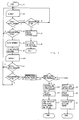
- the throttle valve angle ALPHA is measured in a step S2 after a start step S1.
- the angle ALPHA is compared with an angle ALPHA_ÜBER_MAX.
- This step S3 represents a partial step in the test for a short circuit in the open circuit contact. If the comparison in step S3 is answered in the affirmative and it is determined in the subsequent investigation in step S4 that the open circuit contact is not open, this is the sign for one Short circuit fault.
- This error is displayed in a step S5 and the servomotor is moved to such a position in a step S6 that the throttle valve angle ALPHA_NOT is set when the adjusting screw 17 explained with reference to FIG. 1 abuts the idle contact pin 16.
- the method according to the exemplary embodiment shown in FIG. 2 then ends.
- step S4 If it is determined in step S4 that the open-circuit contact is open, this corresponds to the proper function and the monitoring process starts again with step S2.
- the comparison angle ALPHA_ÜBER_MAX used in step S3 is an angle that is as close as possible to the throttle valve angle ALPHA_MAX that the throttle valve assumes when it is rotated with the aid of the maximum actuating stroke of the actuating shaft 15.
- the idling contact must open if it functions properly. If the actual angle is still below the comparison angle, the described check for a short-circuit fault cannot yet take place, and the method proceeds to a step S7, in which, as in step S4, it is checked whether the open circuit contact is open. Is this if not, the process returns to step S2.
- step S8 is reached in which the current angle ALPHA has registered as angle ALPHA_ ⁇ FFNEN, that is to say as the angle at which the idle contact opened. This angle does not exactly match the actual angle at which the opening took place, since the angle is not detected until step S8 is reached.
- Step S8 is in proper operation, e.g. B. reached every 5 ms. Within this short period of time, the throttle valve angle changes only slightly, even if the throttle valve is quickly adjusted via the adjustment cable 11. The delay in the angle measurement caused by the time grid of the program run therefore does not lead to a major error.
- Opening the idle contact even below the above-mentioned angle ALPHA_MAX is not unusual, since the idle shaft 15 can only be slightly extended, e.g. B. in a warm internal combustion engine, and from this position the throttle valve is adjusted via the adjustment cable 11. However, the opening can also have taken place in that there is an interruption in the idle contact circuit, for. B. in that a contact plug 22 (Fig. 1) has dropped. In order to determine whether the opening was due to an error, test steps S9-S12 follow.
- a throttle valve angle ALPHA_VERMUTET is calculated, which the throttle valve would have to assume if it rests on an actuating shaft that is in a suspected position.
- the angle ALPHA_VERMUTET is composed of the explained angle ALPHA_ ⁇ FFNEN and a correcting angle ALPHA_KORREKTUR.
- the correcting angle includes an angle ALPHA_ÜB, which characterizes a change in angle due to overshoot of the servomotor.
- the current throttle valve angle ALPHA is measured in step S10 and compared in step S11 with the presumed angle ALPHA_MUTEN in step S9. If it is determined that the actual angle has fallen below or is equal to the presumed one, it is checked in step S12 whether the open contact is closed, which should be the case. If the result expected for correct operation is actually determined, the method returns to step S2. There is also a return from step S11 when it is determined that the actual angle is even larger than that suspected. If step S8 is run through again after returning to step S2, the current angle may not again be measured there as the opening angle ALPHA_OPEN.
- step S8 when step S8 is left for the first time, an opening flag is set, which is reset whenever it is determined in step S7 that the no-load contact is not open. Step S8 is only carried out when the flag is reset. Otherwise the angle ALPHA_ ⁇ FFNEN saved the first time is retained.
- step S12 If it is determined in step S12 that the idling contact is still open, even though the actual throttle valve angle is already below the presumed one, a test movement subroutine is executed in a step S13, in which the servomotor is controlled so that it moves should. At the same time, the throttle valve angle ALPHA is measured. If the test movement sequence is evaluated in a step S14 and it is found that the throttle valve angle followed the test movement, this is a sign that the servomotor is working properly, but that the idling contact has an interruption, since it did not close even though the throttle valve on the Actuating shaft system. The stated determination takes place in a step S15 and is displayed in a step S16. In a step S17, an emergency operation setting is carried out, which is identical to that mentioned above under step S6.
- step S14 determines whether the throttle valve angle did follow the movement of the actuating shaft. If it is determined in step S18 that there is a servomotor error, which is indicated in step S19.
- step S20 an emergency running subroutine is executed, which consists in the fuel supply being interrupted whenever the actual throttle valve angle ALPHA falls below the above-mentioned angle ALPHA_ÜBERMAX and at the same time the engine speed rises above an emergency running speed N_NOT.
- the error display according to steps S5, S16 and S19 takes place via a warning lamp and, in addition, by the corresponding error being written into a diagnostic memory. If the warning lamp lights up, the vehicle operator goes to the diagnosis station and this evaluates the content of the diagnosis memory.
- the diagnostic memory In order for the diagnostic memory to receive information that is as reliable as possible, it makes sense not to abort the explained method after steps S6 or S17, as was assumed in the previous explanation, but to let the test procedure run again to determine whether the initially reported error is not due faked another mistake. So in particular a fault diagnosis with regard to the reliability of the throttle valve potentiometer can be carried out. If it turns out during a check of the throttle valve potentiometer that it works inaccurately, it is advantageous to delete a previously identified servomotor error. This prevents an actuator from being replaced unnecessarily. Only when the servo motor fault is determined again after the throttle valve potentiometer has been repaired is it certain that it is really a fault.
- the servomotor control for achieving the emergency running angle ALPHA_NOT according to steps S6 and S17 can take place, as explained above with reference to the prior art. However, it is more advantageous not only to extend the servomotor for a predetermined period of time, starting from its fully retracted position, but to perform such an extension only in a first step. If it is subsequently determined that the continuously monitored throttle valve angle can fall below the angle ALPHA_NOT, this determination is used to extend the adjusting shaft in small, predetermined steps until no further drop in the actual throttle valve angle below the emergency running angle is determined.
- the only condition for triggering the test movement is the determination that the actual throttle valve angle has fallen below the presumed one, but the idle contact is still open. This condition alone would trigger the test movement relatively frequently, since the presumed angle is associated with a relatively wide error range. This is because the structure currently known can only be used to estimate inexactly how far the actuating shaft 15 is actually extended or retracted within a predetermined period of time. Will an arrangement used, which allows a very precise prediction of the position of the actuating shaft on the basis of the actuation times of the servomotor 12, the condition explained with reference to FIG. 2 can be fully sufficient to trigger the test movement.
- the throttle valve angle ALPHA must be smaller than ALPHA_UTMUTET, which angle is calculated according to the above-mentioned type;
- the target angle ALPHA_SOLL for the idle control must be considerably smaller than the presumed angle ALPHA_VERMUTET;
- the throttle valve angle ALPHA must be greater than the above-mentioned emergency running angle ALPHA_NOT.
- the angles mentioned are recorded in FIG. 3 along the ordinate.
- the abscissa is the time axis.
- T_KONST Before the specified time period T_KONST there is a period in which the throttle valve angle ALPHA falls from values above the angle ALPHA_ÜBERMAX to below the presumed angle ALPHA_VERMUTET. The angle remains constant during the period T_KONST.
- the other conditions mentioned above are also met, as can be seen directly by comparing the actual angle with the mentioned swelling angles.
- a test movement sequence is therefore initiated after the period T_KONST has elapsed.
- the test movement sequence according to FIG. 3 is divided into three phases, namely a first of the period T_P1, a second of the period T_P2 and a third of the period T_P3.
- the servomotor is activated for the time T_P1.
- the servomotor is OK, so that the throttle valve angle ALPHA follows the movement of the actuating shaft.
- the second phase there is no actuation of the servomotor, so that the throttle valve angle remains unchanged.
- the servomotor is retracted in the third phase.
- the time period T_P3 corresponds to the time period T_P1 of the first phase.
- the incoming speed is the same as the outgoing speed. If the speeds are different, the running-in time must be measured so that the throttle valve returns to the starting position before the test movement sequence is initiated. The return can also be ensured by continuously comparing the current throttle valve angle with the starting angle at the beginning of the test movement and only adjusting the actuation of the servomotor when the actual angle again matches the starting angle.
- the test movement sequence is followed by an evaluation period T_AUSWERT, in which it is checked whether the throttle valve angle changed at least during phase 1. If this is determined, it is checked whether the throttle valve stopped during phase 2. If this is not the case, the movement must have been caused by the driver and it is also unclear whether the movement was not caused by the driver during phase 1. The test movement can therefore not be evaluated reliably and a further test movement sequence follows as soon as the conditions required for this are all met again. However, if the movement was detected in phase 1 and, if checked, also in phase 3, but no movement took place in phase 2, this is a Sign for correct operation of the servomotor, so that the only cause left for an error is an interruption of the idle contact.
- the servomotor is therefore operated to retract the actuating shaft.
- the specified time is such that the control shaft reaches a position that corresponds to the above-mentioned emergency running angle ALPHA_NOT. If, on the other hand, it is determined during the evaluation phase T_AUSWERT that there was no change in the throttle valve angle in any of the test movement phases, the emergency measure for fuel injection explained above is activated.
- the explained angle ALPHA_ÜBERMAX was used for three different purposes, namely to determine whether there was a short-circuit fault, to determine whether the accelerator has been accelerated since the last test movement sequence and to determine one of the conditions for emergency operation after a detected servomotor fault.
- the angles for the three purposes mentioned can, however, also be dimensioned from different points of view, so that they are then no longer all the same.
- the angle ALPHA_MAX is approximately 20 °.
- the overshoot angle ALPHA_ÜB is typically around 1 °.
- the adjustment movement during the test movement sequence corresponds to approximately 2 ° in a practical test.
- the angle difference in accordance with the above-mentioned condition (4) in the test example is also about 2 °.
- the time T_KONST can be a few 100 ms.
- the size of the emergency running angle ALPHA_NOT strongly depends on the type of internal combustion engine to be controlled. The size of this angle can still be varied depending on the engine temperature, so that it is guaranteed for each temperature that Internal combustion engine does not turn too high, but also does not run out.
- a device for checking the interruption and servomotor errors has a device for monitoring the test conditions and for executing the test movement sequence. There is also an evaluation device for evaluating the test movement sequence and for outputting an error signal.
- the open or servo error check is interrupted as soon as it is determined that the idle contact is now closed.
- the position of this contact is constantly checked.
- the method also returns to its starting point if the closing of the contact is determined during the test movement or during the emergency running phase, provided that the method does not end completely with the setting of the emergency running phase, but is continued, as mentioned above as a variant.
Landscapes
- Engineering & Computer Science (AREA)
- Chemical & Material Sciences (AREA)
- Combustion & Propulsion (AREA)
- Mechanical Engineering (AREA)
- General Engineering & Computer Science (AREA)
- Control Of Throttle Valves Provided In The Intake System Or In The Exhaust System (AREA)
- Electrical Control Of Air Or Fuel Supplied To Internal-Combustion Engine (AREA)
- Combined Controls Of Internal Combustion Engines (AREA)
Abstract
Claims (10)
Applications Claiming Priority (2)
| Application Number | Priority Date | Filing Date | Title |
|---|---|---|---|
| DE3824631A DE3824631A1 (de) | 1988-07-20 | 1988-07-20 | Fehlfunktions-pruefverfahren und -vorrichtung fuer leerlaufregelung |
| DE3824631 | 1988-07-20 |
Publications (2)
| Publication Number | Publication Date |
|---|---|
| EP0378627A1 EP0378627A1 (fr) | 1990-07-25 |
| EP0378627B1 true EP0378627B1 (fr) | 1992-08-26 |
Family
ID=6359141
Family Applications (1)
| Application Number | Title | Priority Date | Filing Date |
|---|---|---|---|
| EP89907085A Expired - Lifetime EP0378627B1 (fr) | 1988-07-20 | 1989-06-29 | Procede et dispositif de controle des defauts de fonctionnement pour le reglage du ralenti |
Country Status (7)
| Country | Link |
|---|---|
| US (1) | US5031595A (fr) |
| EP (1) | EP0378627B1 (fr) |
| JP (1) | JP2813221B2 (fr) |
| KR (1) | KR0141372B1 (fr) |
| DE (2) | DE3824631A1 (fr) |
| ES (1) | ES2017269A6 (fr) |
| WO (1) | WO1990001114A1 (fr) |
Families Citing this family (18)
| Publication number | Priority date | Publication date | Assignee | Title |
|---|---|---|---|---|
| JPH04101043A (ja) * | 1990-08-20 | 1992-04-02 | Mitsubishi Electric Corp | 自動車用電子制御装置 |
| AU3590793A (en) * | 1992-03-27 | 1993-11-08 | Richard W. Armstrong | Automotive diagnostic testing apparatus |
| DE4220286C2 (de) * | 1992-06-20 | 2001-08-09 | Bosch Gmbh Robert | Verfahren zur Funktionsüberprüfung eines Stellelements in einem Fahrzeug |
| DE4221768C2 (de) * | 1992-07-02 | 2002-11-07 | Bosch Gmbh Robert | Verfahren und Vorrichtung zur Steuerung einer Verstelleinrichtung in einem Fahrzeug |
| JPH0650197A (ja) * | 1992-07-28 | 1994-02-22 | Nippondenso Co Ltd | 車両のスロットル弁制御装置 |
| DE4339693A1 (de) * | 1993-11-22 | 1995-05-24 | Bosch Gmbh Robert | Verfahren und Vorrichtung zur Steuerung einer Brennkraftmaschine |
| US5445126A (en) * | 1994-06-24 | 1995-08-29 | Eaton Corporation | Accelerator pedal calibration and fault detection |
| DE19530317C1 (de) * | 1995-08-17 | 1997-03-06 | Siemens Ag | Verfahren zur Lasteinstellung einer Brennkraftmaschine |
| US20010045194A1 (en) * | 1998-04-02 | 2001-11-29 | Takuya Shiraishi | Internal combustion engine control system |
| WO1997013063A1 (fr) * | 1995-10-02 | 1997-04-10 | Hitachi, Ltd. | Dispositif de commande pour moteur a combustion interne |
| JPH09178615A (ja) * | 1995-12-22 | 1997-07-11 | Denso Corp | エンジン回転数制御装置の故障診断装置 |
| SE518099C2 (sv) | 1997-11-21 | 2002-08-27 | Claes Johansson Automotive Ab | Inställbart pedalställ för ett fordon |
| DE19801187B4 (de) * | 1998-01-15 | 2007-07-12 | Robert Bosch Gmbh | Verfahren und Vorrichtung zum Betreiben einer Brennkraftmaschine |
| DE19911214A1 (de) * | 1999-03-12 | 2000-09-21 | Daimler Chrysler Ag | Verfahren zum Betrieb einer Brennkraftmaschine |
| JP4241412B2 (ja) * | 2004-02-03 | 2009-03-18 | 株式会社日立製作所 | 運動機構の駆動制御装置 |
| JP4121091B2 (ja) * | 2005-11-15 | 2008-07-16 | 三菱電機株式会社 | 電子スロットル制御装置 |
| DE102018208037A1 (de) * | 2018-05-23 | 2019-11-28 | Robert Bosch Gmbh | Verfahren zur Diagnose von Ventilsteuerzeiten einer Brennkraftmaschine |
| CN113482773B (zh) * | 2021-07-05 | 2022-05-31 | 无锡威孚高科技集团股份有限公司 | 用于非道路柴油机电控系统的故障管理方法和装置 |
Family Cites Families (17)
| Publication number | Priority date | Publication date | Assignee | Title |
|---|---|---|---|---|
| US4067306A (en) * | 1976-06-24 | 1978-01-10 | Acf Industries, Incorporated | Solenoid operated device to control curb idle position of throttle valve |
| JPS57110736A (en) * | 1980-12-27 | 1982-07-09 | Fuji Heavy Ind Ltd | Apparatus for controlling rotational frequency of engine |
| US4395985A (en) * | 1981-09-08 | 1983-08-02 | Acf Industries, Inc. | Throttle valve closure sensing switch |
| JPS58217744A (ja) * | 1982-05-07 | 1983-12-17 | Honda Motor Co Ltd | 絞り弁開度計測系故障時のアイドル回転数制御方法 |
| JPS59158343A (ja) * | 1983-02-28 | 1984-09-07 | Mitsubishi Motors Corp | エンジンアイドル回転数制御装置 |
| JPS59190441A (ja) * | 1983-04-11 | 1984-10-29 | Nissan Motor Co Ltd | 車両用アクセル制御装置 |
| JPS59190445A (ja) * | 1983-04-11 | 1984-10-29 | Nissan Motor Co Ltd | 車両用アクセル制御装置 |
| JPS6049235U (ja) * | 1983-09-12 | 1985-04-06 | 愛三工業株式会社 | 内燃機関のスロットル制御装置 |
| JPS618441A (ja) * | 1984-06-22 | 1986-01-16 | Nissan Motor Co Ltd | 車両用内燃機関のアクセル制御装置 |
| DE3510176A1 (de) * | 1984-08-16 | 1986-02-27 | Robert Bosch Gmbh, 7000 Stuttgart | Elektronisches fahrpedal fuer ein kraftfahrzeug |
| DE3510173C2 (de) * | 1984-08-16 | 1994-02-24 | Bosch Gmbh Robert | Überwachungseinrichtung für eine elektronisch gesteuerte Drosselklappe in einem Kraftfahrzeug |
| DE3519324A1 (de) * | 1985-05-30 | 1986-12-04 | Robert Bosch Gmbh, 7000 Stuttgart | Stelleinrichtung zur verstellung eines mit einem steuerorgan einer brennkraftmaschine gekoppelten anschlages |
| KR900001627B1 (ko) * | 1986-05-12 | 1990-03-17 | 미쓰비시전기 주식회사 | 내연기관의 아이들회전수 제어장치 |
| US4854283A (en) * | 1986-11-28 | 1989-08-08 | Nippondenso Co., Ltd. | Throttle valve control apparatus |
| JPH0689698B2 (ja) * | 1987-01-23 | 1994-11-09 | 株式会社日立製作所 | 内燃機関制御装置 |
| DE3715557A1 (de) * | 1987-05-09 | 1988-11-24 | Vdo Schindling | Verfahren zur justierung eines stellgliedes und schaltungsanordnung zur durchfuehrung des verfahrens |
| DE3722633A1 (de) * | 1987-07-09 | 1989-01-19 | Vdo Schindling | Elektrisches gaspedal |
-
1988
- 1988-07-20 DE DE3824631A patent/DE3824631A1/de not_active Ceased
-
1989
- 1989-06-29 US US07/466,308 patent/US5031595A/en not_active Expired - Lifetime
- 1989-06-29 EP EP89907085A patent/EP0378627B1/fr not_active Expired - Lifetime
- 1989-06-29 JP JP1506652A patent/JP2813221B2/ja not_active Expired - Fee Related
- 1989-06-29 WO PCT/DE1989/000429 patent/WO1990001114A1/fr not_active Ceased
- 1989-06-29 DE DE8989907085T patent/DE58902154D1/de not_active Expired - Lifetime
- 1989-06-29 KR KR1019900700563A patent/KR0141372B1/ko not_active Expired - Fee Related
- 1989-07-19 ES ES8902550A patent/ES2017269A6/es not_active Expired - Lifetime
Also Published As
| Publication number | Publication date |
|---|---|
| KR0141372B1 (ko) | 1998-07-01 |
| US5031595A (en) | 1991-07-16 |
| JPH03500437A (ja) | 1991-01-31 |
| EP0378627A1 (fr) | 1990-07-25 |
| KR900702204A (ko) | 1990-12-06 |
| JP2813221B2 (ja) | 1998-10-22 |
| WO1990001114A1 (fr) | 1990-02-08 |
| ES2017269A6 (es) | 1991-01-16 |
| DE58902154D1 (de) | 1992-10-01 |
| DE3824631A1 (de) | 1990-01-25 |
Similar Documents
| Publication | Publication Date | Title |
|---|---|---|
| EP0378627B1 (fr) | Procede et dispositif de controle des defauts de fonctionnement pour le reglage du ralenti | |
| DE19647161C2 (de) | Steuerverfahren und Steuervorrichtung für eine Brennkraftmaschine | |
| DE3010975C2 (fr) | ||
| DE3032484A1 (de) | Pruef- und ueberwachungssystem fuer kraftfahrzeuge | |
| DE3249367C1 (en) | Method and device for checking microcomputer-controlled switching devices of control devices in motor vehicles | |
| EP0437559B1 (fr) | Procede et dispositif de commande et/ou de regulation de la puissance du moteur a combustion interne d'un vehicule | |
| DE3928709A1 (de) | Verfahren und vorrichtung zur ueberpruefung der funktionsfaehigkeit einer abgassondenheizung und deren zuleitungssystem | |
| DE19839073C2 (de) | Verfahren und Vorrichtung zur Diagnose einer Zündanlage für eine Brennkraftmaschine | |
| DE19626690A1 (de) | Verfahren und Vorrichtung zur Überwachung eines Kraftstoffzumeßsystems einer Brennkraftmaschine | |
| DE102010043989A1 (de) | Adaptionsverfahren eines Injektors einer Brennkraftmaschine | |
| DE4032451A1 (de) | Einrichtung zur ladedruckregelung | |
| DE19838334A1 (de) | Diagnoseeinrichtung für eine potentiometrische elektrisch beheizte Abgassonde zur Regelung von Verbrennungsprozessen | |
| DE3316660C2 (fr) | ||
| DE10310365B4 (de) | Steuervorrichtung für einen Verbrennungsmotor | |
| DE10345311B4 (de) | Verfahren zum Betreiben einer Brennkraftmaschine, sowie Computerprogramm, elektrisches Speichermedium, Steuer- und/oder Regeleinrichtung und Brennkraftmaschine | |
| DE102007057311B3 (de) | Verfahren und Vorrichtung zur Fehlererkennung bei emissionsrelevanten Steuereinrichtungen in einem Fahrzeug | |
| EP0596297B1 (fr) | Méthode et dispositif pour tester une unité de surveillance de système de commande de moteur | |
| EP0423494B1 (fr) | Procédé et dispositif pour vérifier le fonctionnement de capteurs dans un véhicule | |
| DE102006048227B4 (de) | Verfahren und Vorrichtung zur Ermittlung einer Betriebscharakteristik eines Einspritzsystems sowie ein entsprechend ausgerüsteter Verbrennungsmotor | |
| EP0326693A1 (fr) | Système de sécurité pour moteur à combustion interne | |
| DE3838267C2 (de) | Verfahren und Vorrichtung zur Überwachung eines Sicherheitsabstellers bei Brennkraftmaschinen, insbesondere Dieselmotoren | |
| DE19632339A1 (de) | Verfahren und Vorrichtung zur Überwachung eines Durchflußbegrenzers eines Kraftstoffzumeßsystems einer Brennkraftmaschine | |
| EP1698777B1 (fr) | Procédé pour faire fonctionner un injecteur pour moteur à combustion interne | |
| DE102013213919A1 (de) | Diagnosesystem und -verfahren zum Verarbeiten kontinuierlicher und intermittierender Fehler | |
| DE19956381A1 (de) | Vorrichtung und Verfahren zur Zündung einer Brennkraftmaschine |
Legal Events
| Date | Code | Title | Description |
|---|---|---|---|
| PUAI | Public reference made under article 153(3) epc to a published international application that has entered the european phase |
Free format text: ORIGINAL CODE: 0009012 |
|
| 17P | Request for examination filed |
Effective date: 19900216 |
|
| AK | Designated contracting states |
Kind code of ref document: A1 Designated state(s): DE FR GB IT |
|
| 17Q | First examination report despatched |
Effective date: 19910222 |
|
| RAP3 | Party data changed (applicant data changed or rights of an application transferred) |
Owner name: ROBERT BOSCH GMBH |
|
| GRAA | (expected) grant |
Free format text: ORIGINAL CODE: 0009210 |
|
| AK | Designated contracting states |
Kind code of ref document: B1 Designated state(s): DE FR GB IT |
|
| GBT | Gb: translation of ep patent filed (gb section 77(6)(a)/1977) | ||
| REF | Corresponds to: |
Ref document number: 58902154 Country of ref document: DE Date of ref document: 19921001 |
|
| ET | Fr: translation filed | ||
| ITF | It: translation for a ep patent filed | ||
| PLBE | No opposition filed within time limit |
Free format text: ORIGINAL CODE: 0009261 |
|
| STAA | Information on the status of an ep patent application or granted ep patent |
Free format text: STATUS: NO OPPOSITION FILED WITHIN TIME LIMIT |
|
| 26N | No opposition filed | ||
| REG | Reference to a national code |
Ref country code: GB Ref legal event code: IF02 |
|
| PGFP | Annual fee paid to national office [announced via postgrant information from national office to epo] |
Ref country code: GB Payment date: 20030528 Year of fee payment: 15 |
|
| PGFP | Annual fee paid to national office [announced via postgrant information from national office to epo] |
Ref country code: FR Payment date: 20030619 Year of fee payment: 15 |
|
| PGFP | Annual fee paid to national office [announced via postgrant information from national office to epo] |
Ref country code: DE Payment date: 20030725 Year of fee payment: 15 |
|
| PG25 | Lapsed in a contracting state [announced via postgrant information from national office to epo] |
Ref country code: GB Free format text: LAPSE BECAUSE OF NON-PAYMENT OF DUE FEES Effective date: 20040629 |
|
| PG25 | Lapsed in a contracting state [announced via postgrant information from national office to epo] |
Ref country code: DE Free format text: LAPSE BECAUSE OF NON-PAYMENT OF DUE FEES Effective date: 20050101 |
|
| GBPC | Gb: european patent ceased through non-payment of renewal fee |
Effective date: 20040629 |
|
| PG25 | Lapsed in a contracting state [announced via postgrant information from national office to epo] |
Ref country code: FR Free format text: LAPSE BECAUSE OF NON-PAYMENT OF DUE FEES Effective date: 20050228 |
|
| REG | Reference to a national code |
Ref country code: FR Ref legal event code: ST |
|
| PG25 | Lapsed in a contracting state [announced via postgrant information from national office to epo] |
Ref country code: IT Free format text: LAPSE BECAUSE OF NON-PAYMENT OF DUE FEES;WARNING: LAPSES OF ITALIAN PATENTS WITH EFFECTIVE DATE BEFORE 2007 MAY HAVE OCCURRED AT ANY TIME BEFORE 2007. THE CORRECT EFFECTIVE DATE MAY BE DIFFERENT FROM THE ONE RECORDED. Effective date: 20050629 |