EP0380182A1 - Distributeur - Google Patents
Distributeur Download PDFInfo
- Publication number
- EP0380182A1 EP0380182A1 EP90200168A EP90200168A EP0380182A1 EP 0380182 A1 EP0380182 A1 EP 0380182A1 EP 90200168 A EP90200168 A EP 90200168A EP 90200168 A EP90200168 A EP 90200168A EP 0380182 A1 EP0380182 A1 EP 0380182A1
- Authority
- EP
- European Patent Office
- Prior art keywords
- container
- wall
- applicator
- dispenser
- space
- Prior art date
- Legal status (The legal status is an assumption and is not a legal conclusion. Google has not performed a legal analysis and makes no representation as to the accuracy of the status listed.)
- Granted
Links
- 239000000463 material Substances 0.000 claims abstract description 10
- 238000007598 dipping method Methods 0.000 claims abstract description 7
- 239000011344 liquid material Substances 0.000 claims abstract description 5
- 230000007704 transition Effects 0.000 claims description 5
- XLYOFNOQVPJJNP-UHFFFAOYSA-N water Substances O XLYOFNOQVPJJNP-UHFFFAOYSA-N 0.000 claims description 4
- 238000010521 absorption reaction Methods 0.000 claims description 2
- 230000009471 action Effects 0.000 claims description 2
- 230000015572 biosynthetic process Effects 0.000 claims description 2
- 239000013536 elastomeric material Substances 0.000 claims description 2
- 239000007788 liquid Substances 0.000 abstract description 13
- 230000002706 hydrostatic effect Effects 0.000 description 5
- 238000001035 drying Methods 0.000 description 2
- 230000000694 effects Effects 0.000 description 2
- 230000008901 benefit Effects 0.000 description 1
- POIUWJQBRNEFGX-XAMSXPGMSA-N cathelicidin Chemical compound C([C@@H](C(=O)N[C@@H](CCCNC(N)=N)C(=O)N[C@@H](CCCCN)C(=O)N[C@@H](CO)C(=O)N[C@@H](CCCCN)C(=O)N[C@@H](CCC(O)=O)C(=O)N[C@@H](CCCCN)C(=O)N[C@@H]([C@@H](C)CC)C(=O)NCC(=O)N[C@@H](CCCCN)C(=O)N[C@@H](CCC(O)=O)C(=O)N[C@@H](CC=1C=CC=CC=1)C(=O)N[C@@H](CCCCN)C(=O)N[C@@H](CCCNC(N)=N)C(=O)N[C@@H]([C@@H](C)CC)C(=O)N[C@@H](C(C)C)C(=O)N[C@@H](CCC(N)=O)C(=O)N[C@@H](CCCNC(N)=N)C(=O)N[C@@H]([C@@H](C)CC)C(=O)N[C@@H](CCCCN)C(=O)N[C@@H](CC(O)=O)C(=O)N[C@@H](CC=1C=CC=CC=1)C(=O)N[C@@H](CC(C)C)C(=O)N[C@@H](CCCNC(N)=N)C(=O)N[C@@H](CC(N)=O)C(=O)N[C@@H](CC(C)C)C(=O)N[C@@H](C(C)C)C(=O)N1[C@@H](CCC1)C(=O)N[C@@H](CCCNC(N)=N)C(=O)N[C@@H]([C@@H](C)O)C(=O)N[C@@H](CCC(O)=O)C(=O)N[C@@H](CO)C(O)=O)NC(=O)[C@H](CC=1C=CC=CC=1)NC(=O)[C@H](CC(O)=O)NC(=O)CNC(=O)[C@H](CC(C)C)NC(=O)[C@@H](N)CC(C)C)C1=CC=CC=C1 POIUWJQBRNEFGX-XAMSXPGMSA-N 0.000 description 1
- 230000006835 compression Effects 0.000 description 1
- 238000007906 compression Methods 0.000 description 1
- 239000002537 cosmetic Substances 0.000 description 1
- 229920001971 elastomer Polymers 0.000 description 1
- 239000000806 elastomer Substances 0.000 description 1
- 238000001704 evaporation Methods 0.000 description 1
- 230000008020 evaporation Effects 0.000 description 1
- 238000001746 injection moulding Methods 0.000 description 1
- 230000007246 mechanism Effects 0.000 description 1
- 239000012858 resilient material Substances 0.000 description 1
- 230000007480 spreading Effects 0.000 description 1
Images


Classifications
-
- A—HUMAN NECESSITIES
- A47—FURNITURE; DOMESTIC ARTICLES OR APPLIANCES; COFFEE MILLS; SPICE MILLS; SUCTION CLEANERS IN GENERAL
- A47L—DOMESTIC WASHING OR CLEANING; SUCTION CLEANERS IN GENERAL
- A47L23/00—Cleaning footwear
- A47L23/04—Hand implements for shoe-cleaning, with or without applicators for shoe polish
- A47L23/05—Hand implements for shoe-cleaning, with or without applicators for shoe polish with applicators for shoe polish
-
- B—PERFORMING OPERATIONS; TRANSPORTING
- B65—CONVEYING; PACKING; STORING; HANDLING THIN OR FILAMENTARY MATERIAL
- B65D—CONTAINERS FOR STORAGE OR TRANSPORT OF ARTICLES OR MATERIALS, e.g. BAGS, BARRELS, BOTTLES, BOXES, CANS, CARTONS, CRATES, DRUMS, JARS, TANKS, HOPPERS, FORWARDING CONTAINERS; ACCESSORIES, CLOSURES, OR FITTINGS THEREFOR; PACKAGING ELEMENTS; PACKAGES
- B65D51/00—Closures not otherwise provided for
- B65D51/24—Closures not otherwise provided for combined or co-operating with auxiliary devices for non-closing purposes
- B65D51/32—Closures not otherwise provided for combined or co-operating with auxiliary devices for non-closing purposes with brushes or rods for applying or stirring contents
-
- A—HUMAN NECESSITIES
- A45—HAND OR TRAVELLING ARTICLES
- A45D—HAIRDRESSING OR SHAVING EQUIPMENT; EQUIPMENT FOR COSMETICS OR COSMETIC TREATMENTS, e.g. FOR MANICURING OR PEDICURING
- A45D2200/00—Details not otherwise provided for in A45D
- A45D2200/10—Details of applicators
- A45D2200/1009—Applicators comprising a pad, tissue, sponge, or the like
- A45D2200/1018—Applicators comprising a pad, tissue, sponge, or the like comprising a pad, i.e. a cushion-like mass of soft material, with or without gripping means
-
- A—HUMAN NECESSITIES
- A45—HAND OR TRAVELLING ARTICLES
- A45D—HAIRDRESSING OR SHAVING EQUIPMENT; EQUIPMENT FOR COSMETICS OR COSMETIC TREATMENTS, e.g. FOR MANICURING OR PEDICURING
- A45D34/00—Containers or accessories specially adapted for handling liquid toiletry or cosmetic substances, e.g. perfumes
- A45D34/04—Appliances specially adapted for applying liquid, e.g. using roller or ball
- A45D34/042—Appliances specially adapted for applying liquid, e.g. using roller or ball using a brush or the like
Definitions
- This invention relates to a dispenser for liquid material, such as shoe polish, comprising a container and an applicator by means of which a small quantity of the material can be removed from the container by dipping, and applied to a surface to be treated with the material.
- a drawback of shoe polish dispensers of the above described type is that after some time drying out of the applicator will occur due to evaporation. Another drawback is that it is difficult when dipping a material-receiving end of an applicator into a mass of liquid material, to always absorb a controlled small amount of the material, such as a small amount of shoe polish for spreading it on a shoe surface.
- the container is constructed as a space closed at the top, which communicates exclusively through a passage at its bottom with an adjoining space which is closable by the applicator.
- the container always dispenses so much liquid through the passage to the adjoining space that a hydrostatic equilibrium condition is reached with a low liquid level in the adjoining space and a much higher level in the container, wherein a subatmospheric pressure prevails above the liquid.
- a subatmospheric pressure prevails above the liquid.
- the container is constructed as an annular space bounded by an outer wall and an inner wall and closed at the top, which annular space communicates through a passage near a continuous bottom with a central cavity closable by an applicator having at its lower end an end portion receiving material through absorption, in particular a sponge having substantially the same diameter as the central cavity, in such a manner that when the container is closed the sponge is in contact with the container bottom.
- a dispenser of this type can be manufactured with a loose bottom plate at low cost, e.g. by injection molding. After combining the applicator and the container without the bottom, the dispenser can be filled in the upside down position after which the bottom plate is fitted.
- the applicator there is a screw closure between the applicator and the container, and in the screwed-in position of the applicator the sponge is compressed against the container bottom through a distance at least equal to the screw-in distance.
- the sponge In the closed condition of the dispenser, the sponge is always immersed in liquid and, consequently, cannot dry out.
- the passage from the container to the central cavity is annular and is bounded on the one hand by the bottom plate and on the other hand by a sharp scraper edge extending inwardly from the lower end of the inner wall of the container, by means of which drop formation at the sponge is prevented as the applicator is being taken out.
- the inner wall of the container is formed with a wider upper portion which is connected through an inclined transition to a narrower lower portion, and the applicator is provided above the sponge with a resilient annular edge projecting therefrom, which in unloaded condition has an outside dimension larger than the inside dimension of the narrower lower portion of the container inner wall, as the applicator is being screwed in, the resilient annular edge slides over the inclined transition between the broader and the narrower portion of the container inner wall and ensures an airtight closure of the liquid in the central cavity.
- the applicator is further provided with a grip cap having a free outer edge which, in the screwed-in position of the applicator, abuts sealingly against a corresponding shoulder formed in the outer wall of the container.
- Such a dispenser functions excellently as long as the container is kept upright when the dispenser is open. It is therefore recommendable for the container, when in use to be placed on a flat base, for if the container is canted over while the applicator is being removed from the container, air can penetrate the container and the hydrostatic equilibrium is discontinued temporarily and when the container is again placed in vertical position, equilibrium is established at too high a liquid level in the central cavity.
- the annular passage between the container and the central cavity can be shut off by a plate having a larger diameter than the central cavity and being an axially sliding fit in a cavity formed in the container bottom, and which plate is spring-biased towards the lower edge of the container inner wall, with the applicator being fitted with an extension extending through the sponge, by means of which, with the applicator being in the screwed-in position, the closure plate can be pressed downwards against spring action for clearing the passage.
- the passage between the container and the central cavity is shut off by the plate as soon as the applicator is removed from the central cavity. Even if the container is inclined, no polish can flow in.
- At least one of the coacting threaded portions can be made resilient, e.g. from elastomeric material.
- the sponge can be dipped into the liquid at the bottom of the central cavity by axial compression of the applicator.
- An alternative, constructively chearper embodiment preventing polish from flowing from the container to the central cavity when the open dispenser is canted over is that wherein a baffle is provided in the bottom zone underneath a cover plate, which baffle extends from a position at the container outer wall with a spiral portion to the diametrically opposite side of the container inner wall and which, with a following portion, follows the contour of the container inner wall and terminates within the corner zone comprised by the spiral portion.
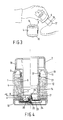
- the dispenser is composed of a container 1 and an applicator 2 connectable thereto by a screw thread 3 to close container 1. It is clear that other closing mechanisms, such as a bayonet fit, can in principle be used.
- the container has a cylindrical outer wall 4 merging via a closed upper wall 5 into a cylindrical inner wall 6, which is connected through an inclined transition 7 to a narrowed lower portion 8 having a sharp, inwardly extending, lower scraper edge 9.
- the container is closable at its lower end with a bottom wall 10.
- the cylindrical outer container wall 4 has a shoulder 11 at the transition to an upper wall 5.
- a reservoir 12 Disposed between the concentric container walls 4 and 6 is a reservoir 12 which communicates via a passage 13 between scraper edge 9 and bottom plate 10 with an adjoining space, in this case a central cavity 14.
- the applicator 2 consists of a shank 15 having a projecting resilient annular edge 16 above a material- receiving end, in this case a sponge 17 having substantially the same diameter as central cavity 14.
- applicator 2 For intermediate dipping of sponge 17, applicator 2 need not always be screwed in, because, as shown on the right in Fig. 1, in the non-compressed state sponge 17 is long enough to reach bottom 10.
- Figs. 2A and 2B show container 1 in opened condition, upright, and in an inclined position.
- air can flow into container space 12, so that the hydrostatic equilibrium is disturbed.
- a level will adjust itself in central cavity 14 that is higher than the level 20 shown in Fig. 1. The unwanted result is that when the sponge is dipped, too much polish is absorbed.
- FIG. 4 A variant embodiment which is insensitive to the tilting of an opened container is shown in Fig. 4, wherein corresponding parts are indicated by like reference numerals as in Figs. 1-3.
- This variant embodiment is distinct from the embodiment shown in Figs. 1-3 by the presence of a closing plate 23 having a larger diameter than central cavity 14 and being received in a cavity 24 formed in the bottom 10′, in which cavity 24 plate 23 is slidable and is loaded upwards by a spring 25. Furthermore, the applicator is provided with an extension 26 engaging with plate 23 and in the embodiment shown, the screw thread 3′ is made at least partly, of resilient material, e,g. an elastomer.
- FIG. 5-6D An alternative embodiment wherein tilting of the container does not disturb the hydrostatic equilibrium either, but in which this effect is achieved otherwise, i.e. without moving parts, is shown in Figs. 5-6D. Again, corresponding parts are designated by like reference numerals as in Fig. 1.
- baffle 27 extends between cover 28 and container bottom 10, with a spiral portion 30 from a position 29 at the container outer wall 4 to a position 31 at the diametrically opposite side of the container inner wall 6 and follows with an arcuate portion 32 the contour of the container inner wall 6 to a position 33 within the corner zone ( ⁇ ) enclosed by spiral portion 30.
- baffle 27 forms a kind of water seal which, on the convex side of spiral portion 30, at the end 34 of cover 28, communicates with container space 12 and on the concave side of the spiral portion 30, is in open communication with central cavity 14 through the - restricted - passage 13′.
- Figs. 7-10 show variants of the embodiment shown in Fig. 5, which have in common with this embodiment that baffle 27 underneath cover plate 28 has a curved portion, extending at least substantially concentrically with the container inner wall and which is connected to the container inner wall 6 and/or to the container outer wall 4 in such a manner that between the bottom 10 of container 1 and cover plate 28, there is formed near the or each baffle 27 a kind of water seal that communicates on the convex side of baffle 27 with container space 12 and on the concave side with container inner space 14.
Landscapes
- Engineering & Computer Science (AREA)
- Mechanical Engineering (AREA)
- Closures For Containers (AREA)
- Coating Apparatus (AREA)
- Treatment Of Fiber Materials (AREA)
- Physical Or Chemical Processes And Apparatus (AREA)
Applications Claiming Priority (2)
| Application Number | Priority Date | Filing Date | Title |
|---|---|---|---|
| NL8900169A NL8900169A (nl) | 1989-01-24 | 1989-01-24 | Doseerpot. |
| NL8900169 | 1989-01-24 |
Publications (2)
| Publication Number | Publication Date |
|---|---|
| EP0380182A1 true EP0380182A1 (fr) | 1990-08-01 |
| EP0380182B1 EP0380182B1 (fr) | 1993-11-18 |
Family
ID=19854011
Family Applications (1)
| Application Number | Title | Priority Date | Filing Date |
|---|---|---|---|
| EP19900200168 Expired - Lifetime EP0380182B1 (fr) | 1989-01-24 | 1990-01-23 | Distributeur |
Country Status (4)
| Country | Link |
|---|---|
| EP (1) | EP0380182B1 (fr) |
| DE (1) | DE69004583T2 (fr) |
| ES (1) | ES2048405T3 (fr) |
| NL (1) | NL8900169A (fr) |
Cited By (11)
| Publication number | Priority date | Publication date | Assignee | Title |
|---|---|---|---|---|
| EP0490449A1 (fr) * | 1990-12-10 | 1992-06-17 | Sara Lee/DE N.V. | Applicateur non-gouttant |
| EP0612488A1 (fr) * | 1993-02-22 | 1994-08-31 | L'oreal | Applicateur |
| FR2754458A1 (fr) * | 1996-10-15 | 1998-04-17 | Oreal | Ensemble d'application d'un produit apte a se solubiliser ou se gelifier en surface au contact d'une composition liquide |
| USRE38016E1 (en) | 1997-02-13 | 2003-03-04 | L'oreal | Application unit for a lipstick-type product |
| WO2005080217A1 (fr) * | 2004-02-17 | 2005-09-01 | Gustav Pfohl Gmbh | Dispositif de stockage et de distribution d'agents coulants |
| FR2890295A1 (fr) * | 2005-09-07 | 2007-03-09 | Bourjois Soc Par Actions Simpl | Dispositif de conditionnement de produit cosmetique fluide a applicateur integre |
| WO2007125141A1 (fr) * | 2006-04-28 | 2007-11-08 | La Superquímica, S.A. | Applicateur |
| JP2009502223A (ja) * | 2005-07-22 | 2009-01-29 | ゾベレ エスパーニャ ソシエダッド アノニマ | フットウェアを手入れするための装置 |
| CN101257829B (zh) * | 2005-07-22 | 2010-06-23 | 索韦莱西班牙股份有限公司 | 鞋护理设备 |
| US9332826B2 (en) | 2014-07-09 | 2016-05-10 | Ricky Spillman, JR. | Cleaning device |
| WO2016135272A1 (fr) | 2015-02-27 | 2016-09-01 | L'oreal | Dispositif cosmétique comportant des compartiments étanches |
Citations (3)
| Publication number | Priority date | Publication date | Assignee | Title |
|---|---|---|---|---|
| FR1131324A (fr) * | 1954-11-30 | 1957-02-20 | Bouchon de récipient pour prélèvement du contenu | |
| FR86430E (fr) * | 1962-07-25 | 1966-02-04 | Dispositif facilitant l'utilisation totale d'un produit liquide ou semi-liquide contenu dans un récipient et l'application de ce produit sur une surface quelconque | |
| DE8713273U1 (de) * | 1987-10-02 | 1988-01-28 | Maaßen, Egon, 2000 Hamburg | Verpackung für lösungsmittelhaltige Flüssigkeiten |
-
1989
- 1989-01-24 NL NL8900169A patent/NL8900169A/nl not_active Application Discontinuation
-
1990
- 1990-01-23 ES ES90200168T patent/ES2048405T3/es not_active Expired - Lifetime
- 1990-01-23 DE DE1990604583 patent/DE69004583T2/de not_active Expired - Fee Related
- 1990-01-23 EP EP19900200168 patent/EP0380182B1/fr not_active Expired - Lifetime
Patent Citations (3)
| Publication number | Priority date | Publication date | Assignee | Title |
|---|---|---|---|---|
| FR1131324A (fr) * | 1954-11-30 | 1957-02-20 | Bouchon de récipient pour prélèvement du contenu | |
| FR86430E (fr) * | 1962-07-25 | 1966-02-04 | Dispositif facilitant l'utilisation totale d'un produit liquide ou semi-liquide contenu dans un récipient et l'application de ce produit sur une surface quelconque | |
| DE8713273U1 (de) * | 1987-10-02 | 1988-01-28 | Maaßen, Egon, 2000 Hamburg | Verpackung für lösungsmittelhaltige Flüssigkeiten |
Cited By (22)
| Publication number | Priority date | Publication date | Assignee | Title |
|---|---|---|---|---|
| EP0490449A1 (fr) * | 1990-12-10 | 1992-06-17 | Sara Lee/DE N.V. | Applicateur non-gouttant |
| US5242232A (en) * | 1990-12-10 | 1993-09-07 | Sara Lee/De N.V. | Anti-drip applicator |
| EP0612488A1 (fr) * | 1993-02-22 | 1994-08-31 | L'oreal | Applicateur |
| FR2701818A1 (fr) * | 1993-02-22 | 1994-09-02 | Oreal | Applicateur. |
| US5492426A (en) * | 1993-02-22 | 1996-02-20 | L'oreal | Deformable applicator with capillary feed |
| USRE37931E1 (en) | 1993-02-22 | 2002-12-10 | L'oreal | Deformable applicator with capillary feed |
| FR2754458A1 (fr) * | 1996-10-15 | 1998-04-17 | Oreal | Ensemble d'application d'un produit apte a se solubiliser ou se gelifier en surface au contact d'une composition liquide |
| EP0836862A1 (fr) * | 1996-10-15 | 1998-04-22 | L'oreal | Ensemble de conditionnement et d'application |
| US5890828A (en) * | 1996-10-15 | 1999-04-06 | L'oreal | Packaging and application unit |
| USRE38016E1 (en) | 1997-02-13 | 2003-03-04 | L'oreal | Application unit for a lipstick-type product |
| WO2005080217A1 (fr) * | 2004-02-17 | 2005-09-01 | Gustav Pfohl Gmbh | Dispositif de stockage et de distribution d'agents coulants |
| EP1571101A1 (fr) * | 2004-02-17 | 2005-09-07 | Gustav Pfohl GmbH | Dispositif de stockage et de distribution de fluide |
| JP2009502223A (ja) * | 2005-07-22 | 2009-01-29 | ゾベレ エスパーニャ ソシエダッド アノニマ | フットウェアを手入れするための装置 |
| CN101257829B (zh) * | 2005-07-22 | 2010-06-23 | 索韦莱西班牙股份有限公司 | 鞋护理设备 |
| EP1917900B1 (fr) * | 2005-07-22 | 2014-05-21 | Zobele España, S.A. | Dispositif pour l'entretien des chaussures |
| FR2890295A1 (fr) * | 2005-09-07 | 2007-03-09 | Bourjois Soc Par Actions Simpl | Dispositif de conditionnement de produit cosmetique fluide a applicateur integre |
| WO2007028901A1 (fr) * | 2005-09-07 | 2007-03-15 | Bourjois | Dispositif de conditionnement de produit cosmetique fluide a applicateur integre |
| WO2007125141A1 (fr) * | 2006-04-28 | 2007-11-08 | La Superquímica, S.A. | Applicateur |
| ES2294925A1 (es) * | 2006-04-28 | 2008-04-01 | La Superquimica S.A. | Aplicador. |
| US9332826B2 (en) | 2014-07-09 | 2016-05-10 | Ricky Spillman, JR. | Cleaning device |
| WO2016135272A1 (fr) | 2015-02-27 | 2016-09-01 | L'oreal | Dispositif cosmétique comportant des compartiments étanches |
| US10758026B2 (en) | 2015-02-27 | 2020-09-01 | L'oreal | Cosmetic device having leaktight compartments |
Also Published As
| Publication number | Publication date |
|---|---|
| DE69004583T2 (de) | 1994-03-10 |
| EP0380182B1 (fr) | 1993-11-18 |
| ES2048405T3 (es) | 1994-03-16 |
| DE69004583D1 (de) | 1993-12-23 |
| NL8900169A (nl) | 1990-08-16 |
Similar Documents
| Publication | Publication Date | Title |
|---|---|---|
| EP0380182B1 (fr) | Distributeur | |
| US5988456A (en) | Closed loop dispensing system | |
| US5031802A (en) | Metering bottle | |
| US4362095A (en) | Storage container for ground coffee | |
| US4168788A (en) | Closure cap and dispenser body assembly | |
| US4875600A (en) | Device for dosing and dispensing a fluid product to be deposited freely in the mobile enclosure of a machine | |
| EP0056126A1 (fr) | Appareil pour alimenter un dispositif d'application en liquide | |
| US2593591A (en) | Adjustable automatic fluid dispenser | |
| US10893664B2 (en) | Animal drinker | |
| US4320859A (en) | Insulated bucket with air pump | |
| US5806240A (en) | System for supplying dripping water to plant growing media | |
| US5242232A (en) | Anti-drip applicator | |
| US2943767A (en) | Constant portion liquid dispenser | |
| CA2074785C (fr) | Contenant a deux compartiments pour le stockage et la distribution de materiel | |
| US5497916A (en) | Liquid dispenser featuring automatic pouring of measured doses | |
| US3023426A (en) | Toilet dispenser | |
| US2913748A (en) | Liquid or cream applicator tops for containers | |
| US2948008A (en) | Dispensing containers | |
| US5682932A (en) | Humidifier water bottle | |
| CA1114555A (fr) | Dispositif debiteur de liquides | |
| EP0135974A2 (fr) | Procédé pour le stockage étanche à l'air d'un produit non-gazeux dans un récipient, ce produit étant destiné à être enlevé par portions de ce récipient; dispositif pour la mise en oeuvre de ce procédé | |
| US3651995A (en) | Squeeze bottle with hydrostatic passage to restrain leakage | |
| US2920795A (en) | Container and dispenser | |
| CN2347953Y (zh) | 调容式精量灌注阀 | |
| US2657826A (en) | Container bottom structure |
Legal Events
| Date | Code | Title | Description |
|---|---|---|---|
| PUAI | Public reference made under article 153(3) epc to a published international application that has entered the european phase |
Free format text: ORIGINAL CODE: 0009012 |
|
| AK | Designated contracting states |
Kind code of ref document: A1 Designated state(s): BE DE ES FR GB NL |
|
| 17P | Request for examination filed |
Effective date: 19900725 |
|
| 17Q | First examination report despatched |
Effective date: 19920825 |
|
| GRAA | (expected) grant |
Free format text: ORIGINAL CODE: 0009210 |
|
| AK | Designated contracting states |
Kind code of ref document: B1 Designated state(s): BE DE ES FR GB NL |
|
| REF | Corresponds to: |
Ref document number: 69004583 Country of ref document: DE Date of ref document: 19931223 |
|
| REG | Reference to a national code |
Ref country code: ES Ref legal event code: FG2A Ref document number: 2048405 Country of ref document: ES Kind code of ref document: T3 |
|
| ET | Fr: translation filed | ||
| PLBE | No opposition filed within time limit |
Free format text: ORIGINAL CODE: 0009261 |
|
| STAA | Information on the status of an ep patent application or granted ep patent |
Free format text: STATUS: NO OPPOSITION FILED WITHIN TIME LIMIT |
|
| 26N | No opposition filed | ||
| PGFP | Annual fee paid to national office [announced via postgrant information from national office to epo] |
Ref country code: GB Payment date: 19950113 Year of fee payment: 6 |
|
| PGFP | Annual fee paid to national office [announced via postgrant information from national office to epo] |
Ref country code: FR Payment date: 19950119 Year of fee payment: 6 |
|
| PGFP | Annual fee paid to national office [announced via postgrant information from national office to epo] |
Ref country code: BE Payment date: 19950127 Year of fee payment: 6 |
|
| PGFP | Annual fee paid to national office [announced via postgrant information from national office to epo] |
Ref country code: NL Payment date: 19950131 Year of fee payment: 6 Ref country code: ES Payment date: 19950131 Year of fee payment: 6 |
|
| PGFP | Annual fee paid to national office [announced via postgrant information from national office to epo] |
Ref country code: DE Payment date: 19950304 Year of fee payment: 6 |
|
| PG25 | Lapsed in a contracting state [announced via postgrant information from national office to epo] |
Ref country code: GB Effective date: 19960123 |
|
| PG25 | Lapsed in a contracting state [announced via postgrant information from national office to epo] |
Ref country code: ES Free format text: LAPSE BECAUSE OF NON-PAYMENT OF DUE FEES Effective date: 19960124 |
|
| PG25 | Lapsed in a contracting state [announced via postgrant information from national office to epo] |
Ref country code: BE Effective date: 19960131 |
|
| BERE | Be: lapsed |
Owner name: SARA LEE/DE N.V. Effective date: 19960131 |
|
| PG25 | Lapsed in a contracting state [announced via postgrant information from national office to epo] |
Ref country code: NL Effective date: 19960801 |
|
| GBPC | Gb: european patent ceased through non-payment of renewal fee |
Effective date: 19960123 |
|
| PG25 | Lapsed in a contracting state [announced via postgrant information from national office to epo] |
Ref country code: FR Effective date: 19960930 |
|
| NLV4 | Nl: lapsed or anulled due to non-payment of the annual fee |
Effective date: 19960801 |
|
| PG25 | Lapsed in a contracting state [announced via postgrant information from national office to epo] |
Ref country code: DE Effective date: 19961001 |
|
| REG | Reference to a national code |
Ref country code: FR Ref legal event code: ST |
|
| REG | Reference to a national code |
Ref country code: ES Ref legal event code: FD2A Effective date: 19990503 |