EP0381437B1 - Magnetronzerstäubungsanlage - Google Patents
Magnetronzerstäubungsanlage Download PDFInfo
- Publication number
- EP0381437B1 EP0381437B1 EP19900300942 EP90300942A EP0381437B1 EP 0381437 B1 EP0381437 B1 EP 0381437B1 EP 19900300942 EP19900300942 EP 19900300942 EP 90300942 A EP90300942 A EP 90300942A EP 0381437 B1 EP0381437 B1 EP 0381437B1
- Authority
- EP
- European Patent Office
- Prior art keywords
- target
- magnetic
- magnetic poles
- magnetron sputtering
- magnetic field
- Prior art date
- Legal status (The legal status is an assumption and is not a legal conclusion. Google has not performed a legal analysis and makes no representation as to the accuracy of the status listed.)
- Expired - Lifetime
Links
Images


Classifications
-
- H—ELECTRICITY
- H01—ELECTRIC ELEMENTS
- H01J—ELECTRIC DISCHARGE TUBES OR DISCHARGE LAMPS
- H01J37/00—Discharge tubes with provision for introducing objects or material to be exposed to the discharge, e.g. for the purpose of examination or processing thereof
- H01J37/32—Gas-filled discharge tubes
- H01J37/34—Gas-filled discharge tubes operating with cathodic sputtering
- H01J37/3411—Constructional aspects of the reactor
- H01J37/3414—Targets
- H01J37/3426—Material
-
- H—ELECTRICITY
- H01—ELECTRIC ELEMENTS
- H01J—ELECTRIC DISCHARGE TUBES OR DISCHARGE LAMPS
- H01J37/00—Discharge tubes with provision for introducing objects or material to be exposed to the discharge, e.g. for the purpose of examination or processing thereof
- H01J37/32—Gas-filled discharge tubes
- H01J37/34—Gas-filled discharge tubes operating with cathodic sputtering
- H01J37/3402—Gas-filled discharge tubes operating with cathodic sputtering using supplementary magnetic fields
- H01J37/3405—Magnetron sputtering
- H01J37/3408—Planar magnetron sputtering
Definitions
- the present invention relates to a magnetron sputtering apparatus and, more particularly, to a magnetron sputtering apparatus capable of readily retaining plasma in a stable manner even in case of a large-scale magnetron or in case where target of a ferromagnetic material is sputtered.
- the present invention also relates to a magnetron sputtering apparatus in which local erosion of the target is blocked, thereby prolonging life of the target, and in which a variation in a sputtering rate can be made to an extremely small extent during operation.
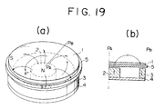
- FIG. 19(a) is a perspective view showing such a magnetron sputtering device
- FIG. 19(b) is a cross-sectional view showing the magnetron sputtering device taken along line P A - P B of FIG. 19(a).
- reference numeral 1 denotes target composed of a non-magnetic material or a ferromagnetic material.
- On the back side of the target 1 are disposed an inner magnetic pole 2 and an outer magnetic pole 3 disposed so as to enclose the inner magnet 2 and having polarity opposite to that of the inner magnetic pole 2.
- a magnetic yoke 4 composed usually of a magnetic material such as steel or the like.
- the sputtering device having the foregoing configuration is accommodated in a vacuum container.
- the container When the magnetron sputtering device is in use, the container is filled with argon gas at low pressures and voltage is applied between the target and a substrate (not shown), such as a disc, thereby ionizing the argon gas and generating electrons from the target surface.
- the argon ions bombard the target to cause the target substance to be generated and to form a thin film on a surface of the substrate.
- the magnetic field formed by the two magnetic poles 2 and 3 can effectively catch the electrons and promote ionization of the argon gas, thereby improving the effectiveness of sputtering.
- Fig. 21 is a cross-sectional view showing a typical erosion pattern of the target 1 in the region between P A - P B of Fig. 19(a) when a ferromagnetic material such as iron or cobalt, is used as the target. As is understood from this drawing, erosion develops locally and the life of the target 1 is shortened considerably.
- a site where erosion mainly develops corresponds well to the position where the polarity of the vertical component of the magnetic field varies rather than the distribution of intensity of the horizontal component thereof, namely, to the position where the value of the vertical component thereof is very small.
- This is considered to be based on the fact that, as shown in Fig. 19(a), the electrons are moving in a cycle along the dome-like magnetic field over the surface of the target 1 as well as, at the same time, making a periodical movement in the direction of gradient in the vertical magnetic field.
- the number of electrons available to ionize argon gas atoms increases where the vertical component of the magnetic field becomes small.
- the outer magnetic pole required for increasing the magnetic flux density comprises the total outer periphery of the magnetron in a semi-circular shape as shown in Fig. 19(a) or it is a portion of the outer magnetic pole 3 for a magnetron in a rectangular shape as shown in Fig. 20, where the magnetic flux spreads in a radial form from the inner magnetic pole 2 to the outer magnetic pole 3.
- magnets are disposed such that centralization of the magnetic flux around the inner magnetic pole is prevented in order to make the magnetic lines of force as parallel as possible to the target surface over the target and the vertical component of the magnetic field is not rendered large around the inner magnetic pole.
- magnetrons present the drawbacks that plasma is likely to become unstable and, when the target is of the ferromagnetic material, the leakage magnetic field over the target surface becomes so small that no plasma is caused at all to occur.
- US-A-4 265 729 discloses a magnetron sputtering apparatus comprising an inner magnetic pole, an outer magnetic pole having a polarity opposite to that of the inner magnetic pole and arranged to surround the inner magnetic pole, and a target disposed at least above the inner magnetic pole and extending therefrom towards the outer magnetic pole, each of the magnetic poles comprising a permanent magnet having magnetization in a direction perpendicular to the plane of the target of a soft magnetic material, and a first permanent magnet having magnetization in a direction parallel to the plane of the target is disposed between the inner and outer magnetic poles.
- the invention is characterised in that a second permanent magnet having magnetization predominantly in a direction opposite to the direction of the magnetization in the first permanent magnet is disposed on an outer side of the outer magnetic pole.
- the invention permits magnetron sputtering apparatus to be constructed which can retain plasma on the target in a stable manner, which prevents local erosion of the target, which can significantly prolong life of the target, and which can sputter the target at a stable sputtering rate during operation, particularly when ferromagnetic material is used as the target.
- Preferred embodiments of apparatus further comprise means disposed between the first permanent magnet and the target and adapted: (a) to decrease, at a central portion between the inner and outer magnetic poles, a vertical (as defined) component of a leakage magnetic field generated by the inner and outer magnetic poles and emerging from the source of the target; (b) to increase the said vertical component thereof at a portion around the magnetic poles; and (c) to cause the distribution of intensity of the horizontal (as defined) component of the magnetic field between the magnetic poles to adopt an M-shaped form, having peaks towards the magnetic poles and a trough therebetween.
- said means comprises a soft magnetic material divided into plural discrete sections by a substance having a narrow width and a low permeability, or by slits, the number of the sections of the soft magnetic material and the width of the low permeability substance or the slits being determined in accordance with the magnetic characteristics or the thickness of the target.
- the number of the sections of the soft magnetic material and the width of the less permeable substance or the slits are optimized in order to optimize the distribution of the magnetic field over the target so as to correspond to magnetic characteristics or the thickness of the target.
- the distributing means is composed of soft magnetic material having a cross-sectional area which is larger at its middle portion and gets gradually smaller towards its end portions, or alternatively is of curved shape, and is disposed such that its curved end portions are further from the target than its central portion.
- the means may be composed of a permanent magnet which has magnetization predominantly in the horizontal direction and which is lower in height at its middle portion and becomes gradually higher towards its end portions, in other words which is arranged such that its central portion comes closer to the target and its end portions are farther therefrom.
- the magnetron sputtering apparatus shown in Fig. 2(a) comprises an inner magnetic pole 12 composed of a soft magnetic material such as steel; and outer magnetic pole 13 disposed so as to enclose the inner magnetic pole 12; a permanent magnet 16 having magnetization predominantly in one horizontal direction with respect of the target 11 disposed between the inner and outer magnetic poles 12, 13; and a permanent magnet 17 having magnetization predominantly in the horizontal direction opposite to that of the permanent magnet 16, disposed on the outer side surface of the outer magnetic pole 13, wherein the magnetic flux density is high around the outer magnetic pole 13.
- the outer magnetic pole 13 may be a soft magnetic material disposed so as to be inclined towards the inside.
- a permanent magnet 17 having a high energy product which is disposed outside the outer magnetic pole 13, in order to allow the outer magnetic pole 13 to produce a sufficiently great magnetic flux density.
- this structure provides the advantage that the size of the magnetron can be smaller.
- the direction of magnetization of the permanent magnet 17 is perpendicular to that of the outer magnetic pole 13 disposed therewithin, the arrangement gives the effect of increasing the magnetic flux density of the outer magnetic pole 13.
- a permanent magnet 17 having this unusual shape can readily be assembled if a plastic magnet made e.g. of a rare earth metal which can be injection- or press-molded is used as the permanent magnet.
- the soft magnetic body 8 is magnetized in the direction toward the outer magnetic pole by means of the magnetic field formed by the inner magnetic pole 2 and the outer magnetic pole 3.
- the magnetization acts over the upper surface of the target 11 in such a manner that the absolute value of the horizontal magnetic field and the gradient of the vertical magnetic field in the middle portion of both magnetic poles 12 and 13 are decreased.
- the influence of the soft magnetic body 8 upon the magnetic field is so small that the gradient of the vertical magnetic field is increased around the upper portion of the two magnetic poles 12 and 13.
- the slits disposed on the soft magnetic body 8 serve to regulate the intensity of magnetization when the soft magnetic body 8 is magnetized by means of the magnetic field generated by the two magnetic poles. More specifically, it is considered that the disposition of the slits causes the magnetic flux to spring out in their positions, and the magnetic field to be generated in the opposite direction at the portions constituting the sections, thereby regulating the intensity of magnetization of the soft magnetic body.
- An accurate control of the distribution of the magnetic field over the upper surface of the target can be implemented by appropriately adjusting the width of the slits of the soft magnetic body 8 and controlling the intensity of magnetization at each section of the soft magnetic body 8.
- a ferromagnetic body when used as the target, adjustment of the slit widths is important.
- the magnetic flux is caused to spring out from the target itself as shown in Fig. 21 so that the magnetic field is increased at the site where erosion has developed, while this increased magnetic field decreases the magnetic field produced by the two magnetic poles on its both sides.
- the plasma is localized at the portion where erosion develops, and no plasma is caused to occur on its both sides.
- erosion proceeds with increasing velocity.
- the target consisting of the ferromagnetic material develops, the magnetic field is increased under the back surface of the target as well as on the upper surface thereof.
- the soft magnetic body 8 used in preferred embodiments of invention has the function of preventing the magnetic field over the target from increasing as a result of an increase in magnetization of the soft magnetic body by means of the increased magnetic field.
- it is necessary to optimize the magnetic characteristics of the soft magnetic body in other words, the number of the sections of the soft magnetic body or the width of the slits disposed thereon - in accordance with the magnetic characteristics of the target or the thickness of the target. As there are gaps between the sections of the soft magnetic body 8, the gaps have the effect of adjusting the magnetic characteristics of the soft magnetic body.
- the widths of the slits permit an accurate distribution of the magnetic field over the target. This adjustment is advantageous because its adjustment is simple. It is to be noted that the slits are not necessarily entirely separate, and they may partially be connected to each other. In both cases, there is no significant difference of the effect. The thickness, length and magnetic characteristics of each section of the soft magnetic body are not necessarily the same as each other and they may vary as needed.
- the soft magnetic body 8B is smaller in cross-sectional area at both end portions so that the amount of the magnetic flux is decreased at both end portions.
- the soft magnetic body 8C is disposed so as to allow both end portions to be farther from the target surface so that the magnetic field varies continuously from the portion where the gradient of the vertical magnetic field is small to the portion where the gradient of the vertical magnetic field is large, compared with the former case.
- This example has the characteristic that periodical changes in the sputtering rate can be small in particular when the target is of ferromagnetic material.
- magnetic bodies 8D and 8E are composed of steel or the like, which is in plate form. In the example of Fig.
- a permanent magnet 8F which has magnetization predominantly in the horizontal direction and is curved in such a concave shape as its thickness is thinner at its central portion and continuously thicker as the distance comes closer to its side portions.
- the permanent magnet 8F is disposed so as to allow its concave surface to face the back surface of the target.
- a permanent magnet 8G is disposed in substantially the same manner as the permanent magnet 8F as shown in Fig. 17, except for its concave face which is indented from its side end portions in a stepwise form. This example has substantially the same effect as the example as shown in FIG. 17.
- the action of compensating the magnetic field is small if the target is of ferromagnetic material as described hereinabove; however, they can be used in case of the target of non-magnetic material, thereby enabling the setting of the distribution of the magnetic field.
- the outer magnet 13 is arranged so as to allow its outer periphery to project over the outer circumference of the target 11. This arrangement, however, can be applied when a magnet 17 disposed outside the outer magnetic pole 13 has a sufficiently large energy product or when the magnet 17 has a sufficient thickness. In this case, the sputtering region can be spread over the outer periphery of the target.
- the magnetic body 8 composed of steel or the like is mounted on the back side of the target in a position between the two magnetic poles. Its section has substantially the same as that taken along line P A - P B in FIG. 20.
- reference numerals 12 and 13 denote inner and outer magnetic poles, respectively, each consisting of soft magnetic material.
- a permanent magnet 16 having horizontal magnetization J is mounted between the two magnetic poles and a permanent magnet 17 having magnetization J' opposite to the magnetization J is stuck to the outer surface of the outer magnetic pole.
- the magnetization may be deviated to some extent from its horizontal direction as long as its main component of the magnetization is substantially horizontal and opposite to that of the other magnetization as shown in FIG.
- the inner and outer magnetic poles 12 and 13 may be of a permanent magnet having magnetization in the vertical direction; however, the energy product of such a permanent magnet varies so that magnetic material such as steel is preferred in order to provide an accurate distribution of the magnetic field.
- the outer magnetic pole 13 requires a uniformity of the magnetic flux density around its outer periphery, use of soft magnetic material is required.
- FIG. 1 shows the soft magnetic body 8A that is disposed in the magnetic field and divided into four sections by slits with a narrow width ranging usually from approximately 0.01 mm to 3 mm, preferably from approximately 0.10 mm to 0.5 mm. Thicknesses of the soft magnetic body 8 range usually from about 1 mm to 10 mm, preferably from about 4 mm to 8 mm.
- the soft magnetic body is fixed with a support plate 9 of non-magnetic material.
- reference numeral 14 stands for a base plate consisting of non-magnetic material and reference numeral 15 for a backing plate to which the target is stuck.
- a target of ferromagnetic material such as FeCo, having diameter of 20,3 cm (8 inches) and thickness of 2.5 mm.
- FIGS. 3(a) and 3(b) show patterns of distributions of the respective horizontal and vertical magnetic fields at 2 mm above the target surface prior to start of the sputtering when the target of ferromagnetic material is applied to the apparatus according to the present invention.
- FIG. 4 shows an erosion pattern of the target after the sputtering.
- FIGS. 22(a) and 22(b) show the same distribution patterns and
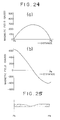
- FIG. 23 shows an erosion pattern in the same conditions, when the same target is applied to the conventional magnetron as shown in FIG. 19.
- erosion occurs locally for the conventional magnetron and it develops with accelerated velocity.
- the region where plasma is closed gets narrower as the erosion develops, thereby rapidly decreasing the sputtering rate as time passes.
- erosion occurs in a wide region and the soft magnetic body 8 compensates the distribution of the magnetic field over the target as the erosion develops, thereby making a periodical variation in the sputtering rate extremely small.
- the magnetic field is set to be the highest around the outside of the inner magnetic pole and to be smaller at a central portion of the inner magnetic pole.
- the distribution of the magnetic field at this portion is outside the present invention.
- the target life is prolonged by larger than five times to approximately 55 kWh from approximately 10 kWh in terms of input power, compared with a conventional magnetron as shown in FIG. 19.
- FIGS. 5(a), 5(b) and 6 represent the second example indicating the distributions of the magnetic field and an erosion pattern, respectively, wherein width of each slit of the soft magnetic body 8 is narrowed so as to make the gradient of the vertical magnetic field virtually null at a portion where the gradient of the vertical magnetic field between the magnetic poles is small.
- the erosion pattern is of a W-shaped form and the target life is approximately 30 kWh. This is because the erosion of the target develops with a slightly faster speed at a portion where a rise in the gradient of the vertical magnetic field is rapid and the action of compensating the magnetic field of the soft magnetic body 8 is not so large at that portion.
- FIGS. 7(a), 7(b) and 8 there is used the target of a Ta non-magnetic material having a 20.3 cm (8-inch) diameter and a 6-mm thickness.
- FIGS. 7(a), 7(b) and 8 represent the distributions of the horizontal and vertical magnetic fields at 2 mm above the target surface prior to the start of sputtering and an erosion pattern of the target subsequent to sputtering, respectively.
- FIGS. 24(a), 24(b) and 25 represent the respective distributions of the horizontal and vertical magnetic fields at 2 mm above the target surface prior to the start of sputtering and an erosion pattern of the target subsequent to sputtering, respectively, using the same target as in the third example for a conventional magnetron as shown in Figure 19.
- erosion occurs locally on the target of non-magnetic material when used with the conventional magnetron, although not so large as with the target of ferromagnetic material. In this case, a utilization efficiency of the target is approximately 25%.
- the soft magnetic body 8 consists of three sections and it accounts for approximately 50% of the distance between its two magnetic poles.
- the gradient of the vertical component of the magnetic field is set to zero at a central portion between the two magnetic poles while the gradient of the horizontal component of the magnetic field is set to a constant value.
- erosion occurs to a larger extent at the central portion between the magnetic poles although an erosion area spreads, as is apparent in FIG. 8.
- the erosion pattern is a loose U-shaped form and a utilization efficiency of the target is 41%.
- the soft magnetic body 8 consists of five sections and the length of the magnetic body 8 accounts for approximately 80% of the distance between the two magnetic poles.
- the distribution of the magnetic field is set so as to allow the gradient of the vertical magnetic field to gradually rise at that portion.
- the width of the slit between two outer sections of the soft magnetic body 8 as shown in the fourth example is somewhat extended from 0.2 mm to 0.3 mm.
- the distributions of the magnetic field and an erosion pattern in this case are shown in FIGS. 11(a) and 11(b) and FIG. 12, respectively. In this case, the utilization efficiency further rises to 66%.
- the minimum value for the horizontal component of the magnetic field at the central portion between the magnetic poles be 70 Gauss, preferably larger than 150 Gauss.
- a variation in curvature of the magnetic field also is a significant factor and it is preferred that changes in the gradient of the magnetic field from a small state to a great state are not sharp.
- the utilization efficiency of the target cannot rise to a very high extent merely by making the direction of the magnetic field over the target parallel to the target surface, and it is thus required that the distribution of the magnetic field be optimized by observing an erosion distribution of the target.
- the slits are disposed in somewhat larger width in advance and soft steel or the like in a ribbon form is inserted into the slits, because this technique does not require that a large number of sections of the soft magnetic body 8A be prepared. It is also preferred that an appropriate substance having a small non-permeability, such as Cu, Al or stainless steel, or a permanent magnet having no magnetization yet a high coercive force may be inserted into the slit without leaving the slit merely as a gap, in order to permit ready positioning of the sections of the soft magnetic body 8A.
- an appropriate substance having a small non-permeability such as Cu, Al or stainless steel, or a permanent magnet having no magnetization yet a high coercive force
- the magnetron sputtering apparatus is provided with the inner magnetic pole consisting of a permanent magnet having magnetization in the vertical direction or a soft magnetic material, an outer magnetic pole consisting of a similar material and disposed so as to enclose the inner magnetic pole, a permanent magnet having magnetization predominantly in the horizontal direction and disposed between the inner and outer magnetic poles, and a magnet having magnetization predominantly in a direction opposite to the horizontal direction of the permanent magnet.
- the apparatus according to the present invention has a sufficiently large degree of the magnetic flux around the outer magnetic pole, thereby permitting plasma to be readily retained in case of a large-scale magnetron or in case where the target is of a ferromagnetic material, and thereby increasing the sputtering rate to a considerable extent, as compared with a usual magnetron.
- the magnetron sputtering apparatus is provided on a back side of the target between the inner and outer magnetic poles with a means for decreasing a component of the leakage magnetic field, vertical to the target, from the inner and outer magnetic poles over a surface of the target disposed on the inner magnetic pole and a magnetic pole in the vicinity of the outer magnetic pole, at a central portion between the inner and outer magnetic poles, yet increasing the vertical component thereof at a portion around the magnetic poles, and for making the distribution of intensity of the horizontal component of the magnetic field in an M-shaped form between the magnetic poles.
- the provision of such a means on the back side of the target between the inner and outer magnetic poles serves as avoiding local erosion of the target and prolonging the target life to a considerable extent. In case of the target of ferromagetic material, a variation in the sputtering rate can be minimized.
- a magnetron sputtering apparatus which permits a ready retention of the plasma and has a wide sputtering area can be provided by combining it with a means using the soft magnetic material having effects on the magnetic field over the upper target surface or with a means using the permanent magnet.
Landscapes
- Physics & Mathematics (AREA)
- Engineering & Computer Science (AREA)
- Plasma & Fusion (AREA)
- Chemical & Material Sciences (AREA)
- Analytical Chemistry (AREA)
- Physical Vapour Deposition (AREA)
Claims (13)
- Magnetronzerstäubungsanlage, die einen inneren Magnetpol (12) umfasst, einen äußeren Magnetpol (13) mit einer Polarität, die derjenigen des inneren Magnetpols (12) entgegengesetzt ist, und der angeordnet ist, um den inneren Magnetpol (12) zu umgeben, ein Target (11), das wenigstens über dem inneren Magnetpol (12) angeordnet ist, und sich davon auf den äußeren Magnetpol (13) hinzu erstreckt, wobei jeder Magnetpol (12, 13) einen Permanentmagneten mit Magnetisierung in einer Richtung senkrecht zur Ebene des Targets (11) aus einem weichmagnetischen Material umfasst, und einen ersten Permanentmagneten (16) mit Magnetisierung in einer Richtung parallel zur Ebene des Targets (11), der zwischen den inneren und äußeren Magnetpolen (12, 13) angeordnet ist, dadurch gekennzeichnet, daß ein zweiter Permanentmagnet (17) mit Magnetisierung hauptsächlich in einer Richtung entgegengesetzt zur Richtung der Magnetisierung in dem ersten Permanentmagneten (16) auf einer äußeren Seite des äußeren Magnetpols (13) angeordnet ist.
- Magnetronzerstäubungsanlage nach Anspruch 1, die weiterhin ein Mittel (8;8B;8C;8D;8E;8F;8G) umfasst, das zwischen dem ersten Permanentmagneten (16) und dem Target (11) zwischen den inneren und äußeren Magnetpolen angeordnet ist, und das angepaßt ist, um: (a) an einem mittleren Teil zwischen den inneren (12) und den äußeren (13) Magnetpolen die Komponente in der Richtung senkrecht zur Ebene des Targets des Magnetfeldes an der Oberfläche des Targets, und das von den inneren (12) und äußeren (13) Magnetpolen erzeugt wird, und von der Oberfläche des Targets (11) austritt, zu verringern; (b) die besagte Komponente in der Richtung senkrecht zur Ebene des Targets an einem Teil um den Magnetpolen (12, 13) zu erhöhen; und (c) die Verteilung der Intensität der Komponente in der Richtung parallel zur Ebene des Targets des Magnetfeldes zwischen den Magnetpolen zu verursachen, um eine M-förmige Gestalt anzunehmen, die Spitzenwerte auf die Magnetpole (12, 13) hinzu hat, und einen Tiefpunkt dazwischen.
- Magnetronzerstäubungsanlage nach Anspruch 2, in der das Mittel (8) ein weichmagnetisches Material umfasst, das durch eine zwischengelagerte Substanz mit geringer Permeabilität, oder durch Schlitze in viele diskrete Abschnitte (8) aufgeteilt ist, wobei die Anzahl von Abschnitten des weichmagnetischen Materials und die Breite der Substanz geringer Permeabilität oder der Schlitze in Übereinstimmung mit der magnetischen Kennzeichnung und der Dicke des Targets (11) bestimmt ist.
- Magnetronzerstäubungsanlage nach Anspruch 2, in der das Mittel (8B) ein weichmagnetisches Material (8B) umfasst, das, wenn man seinen Querschnitt betrachtet, ein Schnittgebiet hat, das an seinem mittleren Teil relativ groß ist, und auf die Endteile in der Nähe der Magnetpole hinzu allmählich kleiner wird.
- Magnetronzerstäubungsanlage nach Anspruch 2, in der das Mittel (8C) ein weichmagnetisches Material (8C) umfasst, das, wenn man seinen Querschnitt betrachtet, gekrümmt ist, und so angeordnet ist, daß es an seinen Endteilen in der Nähe der Magnetpole (12, 13) von dem Target (11) weiter entfernt ist als an einem Teil dazwischen.
- Magnetronzerstäubungsanlage nach Anspruch 2, in der das Mittel (8D; 8E) ein weichmagnetisches Material (8D; 8E) umfasst, wenn man seinen Querschnitt betrachtet, in Gestalt einer Platte mit einer Breite, die 20% bis 80% der Entfernung zwischen den inneren und äußeren Magnetpolen (12, 13) ausmacht.
- Magnetronzerstäubungsanlage nach Anspruch 2, in der das Mittel (8F; 8G) einen Permanentmagneten (8F; 8G) umfasst, der Magnetisierung hauptsächlich in der Richtung parallel zur Ebene des Targets hat, und der, wenn man seinen Querschnitt betrachtet, so angeordnet ist, daß er an seinem mittleren Teil weiter von dem Target (11) entfernt ist, und auf seine Endteile in der Nähe der Magnetpole (12, 13) hinzu allmählich näher an das Target geht.
- Magnetronzerstäubungsanlage nach einem der Ansprüche 2 bis 7, in der die Verteilung der Intensität der Komponente in der Richtung parallel zur Ebene des Targets des Magnetfeldes in der M-förmigen Gestalt so angeordnet ist, daß sein Minimalwert an dem mittleren Teil zwischen den Magnetpolen (12, 13) zwischen 20% und 75% seines Maximalwerts ist.
- Magnetronzerstäubungsanlage nach einem der Ansprüche 2 bis 8, in der die Änderung der Polarität der Komponente in der Richtung senkrecht zur Ebene des Targets des Magnetfeldes zwischen den Magnetpolen (12, 13) an einer Stellung zwischen den Magnetpolen (12, 13) stattfindet, an der der Gradient der Komponente in der Richtung senkrecht zur Ebene des Targets klein ist.
- Magnetronzerstäubungsanlage nach einem der Ansprüche 2 bis 9, in der die Änderung der Polarität der Komponente in der Richtung senkrecht zur Ebene des Targets des Magnetfeldes an einer Stellung zwischen den Magnetpolen (12, 13) in der Nachbarschaft der Stellung des Minimalwerts der Komponente in der Richtung parallel zur Ebene des Targets in dem Tiefpunkt der M-förmigen Verteilungsgestalt stattfindet.
- Magnetronzerstäubungsanlage nach Anspruch 10, in der die Nachbarschaft als die tatsächliche Stellung des Minimalwerts der Komponente in der Richtung parallel zur Ebene des Targets plus oder minus 10% der Entfernung zwischen den Magnetpolen (12, 13) definiert ist.
- Magnetronzerstäubungsanlage nach Anspruch 3, in der ein weichmagnetisches Material in Gestalt eines Bandes in die Schlitze eingeschoben wird, um die Breite der Schlitze einzustellen.
- Magnetronzerstäubungsanlage nach einem der Ansprüche 1 bis 5 oder 8 bis 12, in der das Target (11) aus ferromagnetischem Material besteht.
Priority Applications (1)
| Application Number | Priority Date | Filing Date | Title |
|---|---|---|---|
| EP94117736A EP0645798B1 (de) | 1989-01-30 | 1990-01-30 | Magnetronsputteranlage |
Applications Claiming Priority (2)
| Application Number | Priority Date | Filing Date | Title |
|---|---|---|---|
| JP1770489 | 1989-01-30 | ||
| JP17704/89 | 1989-01-30 |
Related Child Applications (2)
| Application Number | Title | Priority Date | Filing Date |
|---|---|---|---|
| EP94117736A Division EP0645798B1 (de) | 1989-01-30 | 1990-01-30 | Magnetronsputteranlage |
| EP94117736.2 Division-Into | 1990-01-30 |
Publications (3)
| Publication Number | Publication Date |
|---|---|
| EP0381437A2 EP0381437A2 (de) | 1990-08-08 |
| EP0381437A3 EP0381437A3 (de) | 1991-03-27 |
| EP0381437B1 true EP0381437B1 (de) | 1996-06-12 |
Family
ID=11951168
Family Applications (2)
| Application Number | Title | Priority Date | Filing Date |
|---|---|---|---|
| EP19900300942 Expired - Lifetime EP0381437B1 (de) | 1989-01-30 | 1990-01-30 | Magnetronzerstäubungsanlage |
| EP94117736A Expired - Lifetime EP0645798B1 (de) | 1989-01-30 | 1990-01-30 | Magnetronsputteranlage |
Family Applications After (1)
| Application Number | Title | Priority Date | Filing Date |
|---|---|---|---|
| EP94117736A Expired - Lifetime EP0645798B1 (de) | 1989-01-30 | 1990-01-30 | Magnetronsputteranlage |
Country Status (5)
| Country | Link |
|---|---|
| EP (2) | EP0381437B1 (de) |
| JP (1) | JPH0774439B2 (de) |
| CA (2) | CA2008934C (de) |
| DE (2) | DE69027344T2 (de) |
| SG (1) | SG50498A1 (de) |
Families Citing this family (11)
| Publication number | Priority date | Publication date | Assignee | Title |
|---|---|---|---|---|
| JPH02118750U (de) * | 1989-03-08 | 1990-09-25 | ||
| DE69433208T2 (de) * | 1993-10-22 | 2004-08-05 | Manley, Barry, Boulder | Verfahren und vorrichtung zum sputtern von magnetischem targetmaterial |
| NL1000139C2 (nl) * | 1995-04-13 | 1996-10-15 | Od & Me Bv | Magnetronsputtersysteem. |
| DE19622606C2 (de) * | 1996-06-05 | 2002-02-28 | Applied Films Gmbh & Co Kg | Sputterkathode |
| DE19622605A1 (de) * | 1996-06-05 | 1997-12-11 | Leybold Systems Gmbh | Sputterkathode |
| DE19708344A1 (de) * | 1997-03-01 | 1998-09-03 | Leybold Systems Gmbh | Sputterkathode |
| RU2135634C1 (ru) * | 1998-06-15 | 1999-08-27 | Санкт-Петербургский государственный технический университет | Способ и устройство магнетронного распыления |
| DE19836125C2 (de) * | 1998-08-10 | 2001-12-06 | Leybold Systems Gmbh | Zerstäubungsvorrichtung mit einer Kathode mit Permanentmagnetanordnung |
| US7182843B2 (en) * | 2003-11-05 | 2007-02-27 | Dexter Magnetic Technologies, Inc. | Rotating sputtering magnetron |
| US20070246354A1 (en) * | 2006-04-19 | 2007-10-25 | Maxim Integrated Products, Inc. | Plasma systems with magnetic filter devices to alter film deposition/etching characteristics |
| WO2017221821A1 (ja) * | 2016-06-21 | 2017-12-28 | 株式会社アルバック | ターゲット装置、スパッタリング装置 |
Family Cites Families (4)
| Publication number | Priority date | Publication date | Assignee | Title |
|---|---|---|---|---|
| US4265729A (en) * | 1978-09-27 | 1981-05-05 | Vac-Tec Systems, Inc. | Magnetically enhanced sputtering device |
| CH648690A5 (de) * | 1980-10-14 | 1985-03-29 | Balzers Hochvakuum | Kathodenanordnung zur abstaeubung von material von einem target in einer kathodenzerstaeubungsanlage. |
| EP0144838B1 (de) * | 1983-12-05 | 1989-10-11 | Leybold Aktiengesellschaft | Magnetronkatode zum Zerstäuben ferromagnetischer Targets |
| JPH0633454B2 (ja) * | 1984-11-20 | 1994-05-02 | 松下電器産業株式会社 | スパツタリング装置 |
-
1990
- 1990-01-26 JP JP2014992A patent/JPH0774439B2/ja not_active Expired - Lifetime
- 1990-01-30 DE DE1990627344 patent/DE69027344T2/de not_active Expired - Lifetime
- 1990-01-30 DE DE1990631743 patent/DE69031743T2/de not_active Expired - Lifetime
- 1990-01-30 EP EP19900300942 patent/EP0381437B1/de not_active Expired - Lifetime
- 1990-01-30 CA CA 2008934 patent/CA2008934C/en not_active Expired - Fee Related
- 1990-01-30 CA CA 2202801 patent/CA2202801A1/en not_active Abandoned
- 1990-01-30 SG SG1996002853A patent/SG50498A1/en unknown
- 1990-01-30 EP EP94117736A patent/EP0645798B1/de not_active Expired - Lifetime
Also Published As
| Publication number | Publication date |
|---|---|
| DE69031743T2 (de) | 1998-03-12 |
| DE69027344D1 (de) | 1996-07-18 |
| EP0381437A2 (de) | 1990-08-08 |
| JPH02277772A (ja) | 1990-11-14 |
| EP0381437A3 (de) | 1991-03-27 |
| CA2008934A1 (en) | 1990-07-30 |
| EP0645798B1 (de) | 1997-11-19 |
| CA2008934C (en) | 1997-06-17 |
| DE69031743D1 (de) | 1998-01-02 |
| SG50498A1 (en) | 1998-07-20 |
| JPH0774439B2 (ja) | 1995-08-09 |
| CA2202801A1 (en) | 1990-07-30 |
| DE69027344T2 (de) | 1996-10-10 |
| EP0645798A1 (de) | 1995-03-29 |
Similar Documents
| Publication | Publication Date | Title |
|---|---|---|
| EP0442939B1 (de) | Kathode zum magnetronsputtern | |
| US4964968A (en) | Magnetron sputtering apparatus | |
| US5876576A (en) | Apparatus for sputtering magnetic target materials | |
| KR100396456B1 (ko) | 절단된 코니칼 스퍼터링 타겟용 고 타겟 이용 자기 장치 | |
| US4865708A (en) | Magnetron sputtering cathode | |
| US4872964A (en) | Planar magnetron sputtering apparatus and its magnetic source | |
| US4239611A (en) | Magnetron sputtering devices | |
| US4401539A (en) | Sputtering cathode structure for sputtering apparatuses, method of controlling magnetic flux generated by said sputtering cathode structure, and method of forming films by use of said sputtering cathode structure | |
| US5174880A (en) | Magnetron sputter gun target assembly with distributed magnetic field | |
| US4404077A (en) | Integrated sputtering apparatus and method | |
| EP0381437B1 (de) | Magnetronzerstäubungsanlage | |
| EP0093412A1 (de) | Magnetron-Sputtervorrichtungsowie Verfahren zur Herstellung einer magnetischen Dunnschicht auf der Oberfläche eines Substrats | |
| US5277779A (en) | Rectangular cavity magnetron sputtering vapor source | |
| US6432285B1 (en) | Planar magnetron sputtering apparatus | |
| CN110791742A (zh) | 一种磁控溅射阴极的磁源结构及其调节磁场的方法 | |
| GB2051877A (en) | Magnetically Enhanced Sputtering Device and Method | |
| GB2096177A (en) | Improved integrated sputtering apparatus and method | |
| Spencer et al. | The design and performance of planar magnetron sputtering cathodes | |
| RU2107971C1 (ru) | Магнетронная распылительная система | |
| EP0197770B1 (de) | Flache Magnetron-Penning-Entladungszerstäubungsvorrichtung | |
| Nakamura et al. | " GT target", A new high rate sputtering target of magnetic materials | |
| JPH0784659B2 (ja) | スパッタリングターゲット | |
| JP2769572B2 (ja) | マグネトロンスパッタリング用カソード | |
| JPS61204371A (ja) | 陰極スパツタリング用磁気回路装置 | |
| JP3023270B2 (ja) | マグネトロンスパッタ用磁気回路 |
Legal Events
| Date | Code | Title | Description |
|---|---|---|---|
| PUAI | Public reference made under article 153(3) epc to a published international application that has entered the european phase |
Free format text: ORIGINAL CODE: 0009012 |
|
| AK | Designated contracting states |
Kind code of ref document: A2 Designated state(s): DE FR GB IT NL |
|
| 17P | Request for examination filed |
Effective date: 19901212 |
|
| PUAL | Search report despatched |
Free format text: ORIGINAL CODE: 0009013 |
|
| AK | Designated contracting states |
Kind code of ref document: A3 Designated state(s): DE FR GB IT NL |
|
| 17Q | First examination report despatched |
Effective date: 19930729 |
|
| RAP1 | Party data changed (applicant data changed or rights of an application transferred) |
Owner name: MITSUBISHI CHEMICAL CORPORATION |
|
| GRAH | Despatch of communication of intention to grant a patent |
Free format text: ORIGINAL CODE: EPIDOS IGRA |
|
| GRAH | Despatch of communication of intention to grant a patent |
Free format text: ORIGINAL CODE: EPIDOS IGRA |
|
| GRAA | (expected) grant |
Free format text: ORIGINAL CODE: 0009210 |
|
| AK | Designated contracting states |
Kind code of ref document: B1 Designated state(s): DE FR GB IT NL |
|
| PG25 | Lapsed in a contracting state [announced via postgrant information from national office to epo] |
Ref country code: IT Free format text: LAPSE BECAUSE OF FAILURE TO SUBMIT A TRANSLATION OF THE DESCRIPTION OR TO PAY THE FEE WITHIN THE PRE;WARNING: LAPSES OF ITALIAN PATENTS WITH EFFECTIVE DATE BEFORE 2007 MAY HAVE OCCURRED AT ANY TIME BEFORE 2007. THE CORRECT EFFECTIVE DATE MAY BE DIFFERENT FROM THE ONE RECORDED.SCRIBED TIME-LIMIT Effective date: 19960612 Ref country code: FR Effective date: 19960612 |
|
| XX | Miscellaneous (additional remarks) |
Free format text: TEILANMELDUNG 94117736.2 EINGEREICHT AM 30/01/90. |
|
| REF | Corresponds to: |
Ref document number: 69027344 Country of ref document: DE Date of ref document: 19960718 |
|
| EN | Fr: translation not filed | ||
| PLBE | No opposition filed within time limit |
Free format text: ORIGINAL CODE: 0009261 |
|
| STAA | Information on the status of an ep patent application or granted ep patent |
Free format text: STATUS: NO OPPOSITION FILED WITHIN TIME LIMIT |
|
| 26N | No opposition filed | ||
| PGFP | Annual fee paid to national office [announced via postgrant information from national office to epo] |
Ref country code: NL Payment date: 19990131 Year of fee payment: 10 |
|
| PG25 | Lapsed in a contracting state [announced via postgrant information from national office to epo] |
Ref country code: NL Free format text: LAPSE BECAUSE OF NON-PAYMENT OF DUE FEES Effective date: 20000801 |
|
| NLV4 | Nl: lapsed or anulled due to non-payment of the annual fee |
Effective date: 20000801 |
|
| REG | Reference to a national code |
Ref country code: GB Ref legal event code: IF02 |
|
| PGFP | Annual fee paid to national office [announced via postgrant information from national office to epo] |
Ref country code: DE Payment date: 20090219 Year of fee payment: 20 |
|
| PGFP | Annual fee paid to national office [announced via postgrant information from national office to epo] |
Ref country code: GB Payment date: 20081229 Year of fee payment: 20 |
|
| REG | Reference to a national code |
Ref country code: GB Ref legal event code: PE20 Expiry date: 20100129 |
|
| PG25 | Lapsed in a contracting state [announced via postgrant information from national office to epo] |
Ref country code: GB Free format text: LAPSE BECAUSE OF EXPIRATION OF PROTECTION Effective date: 20100129 |
|
| PG25 | Lapsed in a contracting state [announced via postgrant information from national office to epo] |
Ref country code: DE Free format text: LAPSE BECAUSE OF EXPIRATION OF PROTECTION Effective date: 20100130 |