EP0384052B1 - Ein Gerät zur Kontrolle des Schwenkwinkels eines Ventilators - Google Patents
Ein Gerät zur Kontrolle des Schwenkwinkels eines Ventilators Download PDFInfo
- Publication number
- EP0384052B1 EP0384052B1 EP19890301753 EP89301753A EP0384052B1 EP 0384052 B1 EP0384052 B1 EP 0384052B1 EP 19890301753 EP19890301753 EP 19890301753 EP 89301753 A EP89301753 A EP 89301753A EP 0384052 B1 EP0384052 B1 EP 0384052B1
- Authority
- EP
- European Patent Office
- Prior art keywords
- gear
- spindle
- hollow shaft
- main gear
- carrier
- Prior art date
- Legal status (The legal status is an assumption and is not a legal conclusion. Google has not performed a legal analysis and makes no representation as to the accuracy of the status listed.)
- Expired - Lifetime
Links
- 238000010408 sweeping Methods 0.000 claims description 37
- 230000007246 mechanism Effects 0.000 description 19
- 230000008859 change Effects 0.000 description 8
- 238000006073 displacement reaction Methods 0.000 description 5
- 238000010276 construction Methods 0.000 description 3
- 230000010355 oscillation Effects 0.000 description 3
- 230000009471 action Effects 0.000 description 2
- 238000012886 linear function Methods 0.000 description 2
- 229910000831 Steel Inorganic materials 0.000 description 1
- 230000004075 alteration Effects 0.000 description 1
- 230000005540 biological transmission Effects 0.000 description 1
- 238000006243 chemical reaction Methods 0.000 description 1
- 230000003247 decreasing effect Effects 0.000 description 1
- 238000010586 diagram Methods 0.000 description 1
- 238000000034 method Methods 0.000 description 1
- 230000008569 process Effects 0.000 description 1
- 230000000630 rising effect Effects 0.000 description 1
- 239000010959 steel Substances 0.000 description 1
- 230000001360 synchronised effect Effects 0.000 description 1
Images


Classifications
-
- F—MECHANICAL ENGINEERING; LIGHTING; HEATING; WEAPONS; BLASTING
- F04—POSITIVE - DISPLACEMENT MACHINES FOR LIQUIDS; PUMPS FOR LIQUIDS OR ELASTIC FLUIDS
- F04D—NON-POSITIVE-DISPLACEMENT PUMPS
- F04D25/00—Pumping installations or systems
- F04D25/02—Units comprising pumps and their driving means
- F04D25/08—Units comprising pumps and their driving means the working fluid being air, e.g. for ventilation
- F04D25/10—Units comprising pumps and their driving means the working fluid being air, e.g. for ventilation the unit having provisions for automatically changing direction of output air
- F04D25/105—Units comprising pumps and their driving means the working fluid being air, e.g. for ventilation the unit having provisions for automatically changing direction of output air by changing rotor axis direction, e.g. oscillating fans
Definitions
- This invention relates to a device for controlling the sweeping-angle of a fan and more particularly to a device suitable for controlling the amplitude of the sweeping-angle when the fan sweeps according to the pre-characterizing part of Claim 1. and as known from US-A-2.791.122.
- the sweeping device in conventional electrical fan usually is a four-bar linkage.
- the length of one of the bars should be changed and usually that is the crank.
- the elastic force caused by spring or the friction force between the pin and slot should be as small as possible to make the motion of the pin or slidable bar easy.
- the above said forces should be large enough to withstand the reaction force caused by connecting bar during the rotation of the crank and therefore to ensure that the pin can be positioned and fixed securely after being adjusted.
- it is very difficult to make a compromise especially because of the limited space in the gear box of the sweeping device. So either such a sweeping device based on the above scheme will not be easy in adjusting or the sweeiping angle will shift from preset value during operation.
- a top-controlled oscillating mechanism for an electric fan has a vertically disposed hollow shaft driven by the electric motor to one end of which is connected a housing for rotation with the shaft.
- a control stem is located within the hollow shaft and is capable of relative rotation thereto.
- a pinion gear is secured to the control stem and is for engagement with a disc located within an eccentric cavity in the housing located on the hollow shaft.
- a crank pin and a link member are connected to the disc for controlling the oscillation of the fan.
- the object of the present invention is to solve above problem exsisting in the prior art.
- the sweeping device of the present invention is ont only easy in adjusting, but also capable of keeping the crank length constant and consequently making the fan always sweep with a predetermined angle.
- a planet gear system which comprises a sun gear, a planet gear and a planetary carrier.
- An eccentric pin is fixed on the planet gear, and the sun gear meshes with said planet gear during operation.
- the planet gear is pivotally mounted on the planetary carrier which is fixedly connected with a hollow shaft.
- the sun gear is fixedly connected with a spindle which is coaxially arranged in said hollow shaft.
- the distance between the axis of the eccentric pin fixed on the planet gear and the axis of the sun gear or the axis of the spindle can be continuously changed,and a length changeable crank is formed between the two axes.
- the distance between said two axes, i.e. the crank length will be kept constant when the rotation of the planetary carrier is synchronized with that of the sun gear. If said distance between the pin axis and the planet gear axis is equal to the distance between the planet gear axis and the sun gear axis, the crank length will be changeable from zero to maximum value.
- the maximum crank length will be twice the distance between the planet gear axis and the sun gear axis.
- the fan can sweep with a sweeping angle adjustable from zero to maximum value.
- a main gear is mounted on one of said spindle and said hollow shaft, the main gear is meshed with a worm gear shaft in conventional sweeping device , by which power is transmitted to sweep the fan and change the crank length.
- a clutch is arranged between the hollow shaft and spindle to permit relative rotation of the hollow shaft and spindle while adjusting the crank length and ensure a fixed crank length after obtaining desired crank length by engaging the clutch so that the hollow shaft and spindle are rotating synchronously.
- the clutch may be of ratchet type, or a friction disk type, or other suitable type. With the clutch being engaged, the spindle and the hollow shaft are locked with each other, thus said planetary gear system becomes a gear system with fixed axes, the sun gear, the planet gear, the planetary carrier and the eccentric pin all rotating about the axis of the sun gear, and the crank rotating with a fixed length previously set.
- the engaging and disengaging of the clutch is performed by an adjusting mechanism.
- the adjusting mechanism according to the present invention may be of manually operated type or automatically operated type.
- the principle of the manual adjusting mechanism is as follows: the clutch is first manually disengaged by an user and the crank length is changed. Then the length change is fed back by some electric or mechanical means and shown on some kind of indicator.When the crank length corresponding to a sweeping angle is shown as desired,the clutch is then manually engaged and the fan will sweep within the adjusted angle.
- the principle of operation of the automatic adjusting mechanism is as follows: an instruction for adjusting to a desired sweeping angle is input to the adjusting mechanism. The automatic adjusting mechanism then will automatically disengage the clutch and adjust the crank length.When the adjusted crank length corresponds to the desired sweeping angle, the clutch will automatically be engaged by the adjusting mechanism. Thus the fan will sweep within the desired sweeping angle.
- a sun gear and a planetary carrier are respectively fixed at the lower end of the spindle and the hollow shaft; a main gear meshed with a worm gear shaft is fixed at the upper end of the hollow shaft, a closed cam surface is integrated formed on the main gear, a carrier is securely mounted on the upper end of the spindle.
- the clutch is of a ratchet-pawl type, the ratchet is the above said main gear and the pawl mounted on the carrier is biased into engagement by a spring means; a supproter, which can rotate in a horizontal plane about a vertical pin, is mounted on the carrier.
- the supporter comprises a pushing plate and a swinging bar which can rotate about a horizontal pin on the supporter in a vertically plane and is biased downwardly by a spring means.
- a baffle is mounted n the casing of the device capable of moving only in one direction, for example, reciprocating in vertical direction, on the lateral of the baffle there is a notch only through which can the free end of the swinging bar rotate with the carrier.
- the front end of said pushing plate is abutted upon the pawl.
- the pushing plate is integrated with a stopper cooperated with a stopping surface formed on the carrier to delimit the motion of the supporter.
- a follower reciprocally movable is also mounted on the carrier.
- One end of the follower is abutted against the swinging bar and another end can slide along the above said cam surface.
- the rising and falling of the cam surface causes the follower to reciprocate in approximately vertical direction.
- the cam surface may also undulate llaterally so that the follower reciprocates in approximately horizontal direction.
- the swinging bar can be saved and the follower mavable in horizontal direction can directly cooperate with the notch of the baffle which moves reciprocally in approximately horizontal direction.
- crank length can be varied from zero to maximum value at your will. That is to say, the fan with the controlling device of the present invention can sweep with any sweeping angle ranging from zero to maximum value as desired.
- the crank length adjusting is very easy and convenient.
- the power for adjusting the crank length is provided by the fan motor, and the crank length after adjusting is fixed by the engaged clutch so that it will remain unchanged.
- the device according to the present invention therefore has the advantages of being easy and convenient in adjusting and being smooth and reliable in running.
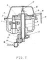
- a worm gear 1 is meshed with a worm 2 connected with a motor shaft. Motion can be transmitted to a main gear 5 by a worm gear shaft 3.
- a well known unloading means and a clutch (not shown) are arranged between the worm gear 1 and its shaft 3. When the loading of the worm gear is increased up to a certain value , the unloading means will automatically make the connection between the worm gear 1 and the worm gear shaft 3 released, the clutch means controls the fan to stay in a fixed direction.
- the teeth meshed with the main gear 5 are directly formed on the upper end of the worm gear shaft 3, by which the power can be transmitted to the main gear 5.
- the main gear 5 is mounted on the upper end of a hollow shaft 6 ( or a spindle 7), the spindle 7 being rotatable with respect to the hollow shaft 6 is coaxially arranged in the hollow shaft 6.
- the lower end of the hollow shaft 6 is securely connected with a planetary carrier 9 by a screw 8.
- a planet gear 11 with a eccentric pin 10 is pivoted on the planetary carrier 9 by a pin 13.
- a sun gear 12 is fixed on the spindle.
- the planet gear 11 can rotate about the pin 13 and is meshed with the sun gear 12.
- a planetary gear system is formed by the sun gear 12, the planet gear 11 and the planetary carrier 9.
- the s indle 7 may rotate with respect to the hollow shaft 6 which is connected with the planetary carrier 9.
- the planet gear 11 is eccentrically equipped with a crank pin 10 which may be int grated with the planet gear 11. Pivoted with the pin 10 is one end of a connecting bar 14.
- the planet gear 11 will rotate with respect to the sun gear 12 and this will continuously change the distance between the axis of the crank pin 10 and the axis of the spindle 7, forming a length changeable crank.
- the distance between the axes of the crank pin 10 and the planet gear 11 is selected to be equal to the centre-to-centre distance between the sun gear 12 and the planet gear 11.
- the crank length can be varied from zero to a maximum value which is twice the centre-to-centre distance between the sun gear 12 and the planet gear 11.
- the sweeping angle of the improved fan may be varied from zero to a maximum value, for instance 120°. Power is transmitted from the fan motor (not shown) to the main gear 5 through the worm 2, the worm gear 1 and the worm gear shaft 3. The four bars linkage will then swing accordingly, and the fan will sweep with the swinging of the one of said four bars.
- a clutch means is arranged between the hollow shaft 6 and the spindle 7.
- the clutch means may be of a ratchet type or a friction type or other suitable type.
- the 'engaging' and 'disengaging' positions of the clutch can be controlled either manually or automatically.
- the clutch means used in the first embodiment is of a manually operated friction type, wherein a friction disk 16 is biased to abut on the upper end surface of the main gear 5 by a spring 17 via a steel ball 18, as shown in Fig. 1. One end of the spring 17 is abutted on a cover 15.
- An operating lever 19 is used to raise the friction disk 16 so as to separate it from the main gear 5, a clamping slot 20 is formed on the free end of the lever 19 for braking the friction disk 16 after separating.
- the action of the lever 19 is controlled via a pulling cable 21 by a key (not shown) mounted on the controlling board of a fan.
- the friction disk 16 When the key is released, the friction disk 16 is connected with the main gear 5, integrating the hollow shaft 6, the spindle7, the planetary carrier 9, the planet gear 11, the sun gear 12 and the crank pin 10, thus abtaining a gear system with fixed axes operates with a constant crank length which determines the fan's sweeping angle.
- the solid line in Fig. 2 shows the position of the system with a maximum crank length. If the sweeping angle is to be changed to the position as shown in dotted line in Fig. 2, the key is pressed to cause the friction disk 16 to separated from the main gear 5 by the lever 19. The clamping slot 20 then brakes the friction disk 16.
- the planet gear 11 and the crank pin 10 will be forced to rotate about the pin 13 so that the crank length will be changed.
- the key is released to bring the friction clutch into engagement.
- the fan will sweep with a new sweeping angle which is determined by the changed crank length.
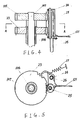
- a driven gear 23 which has the same teeth number and modulus as the main gear 105.
- Said gear 23 is mounted on the hollow shaft 106 and the gear 105 is mounted on the spindle 107.
- a clutch means comprises a pinion 25 and an escapement lever which may pivot about a pin 26.
- said pinion 25 is rotatably mounted on the escapement lever 24 which has a tip at one end thereof.
- the spring force caused by a spring 27 will make the pinion 25 meshed with both gear 105 and gear 23 and that is the 'engaging' position of the clutch means as shown in Fig. 5.
- Motor power can be directly transmitted either to the gear 105 or the gear 23. In this embodiment, the motor power is transmitted to the gear 105(not shown).
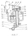
- Figs. 7 to 11 show another embodiment of the present invention, wherein the sweeping angle in this embodiment is automatically adjusted.
- the adjusting mechanism of the device By inputting a desired sweeping angle signal, the adjusting mechanism of the device will automatically control the engaging and disengaging positions of the clutch means and find the corresponding crank length.
- the planetary gear system in this embodiment is the same as above mentioned embodiments and description is omitted here.
- a worm 202 connected with a motor is meshed with a worm gear 201.
- Motion is transmitted by the worm gear shaft 203 to a main gear 205.
- the well known unloading means and a clutch (not shown) are arranged between the worm gear 201 and its shaft 203.
- the unloading means will automatically make the connection between the worm gear 201 and the shaft 203 released.
- Said clutch is used to control the fan to stay at an orientation position,
- the teeth meshed with the main gear 205 are directly formed on the upper end of the worm gear shaft 203, of which is rotatably mounted on a casing of the device.
- the main gear 205 may be fixed on either a hollow shaft 206 or on a spindle 207, i.e. power is introduced wither to the hollow shaft 206 or to the spindle 207.
- the motor power is introduced to the hollow shaft 206 and a carrier 28 is therefore mounted on the spindle 207.
- a carrier 28 is therefore mounted on the spindle 207.
- Such an arrangement is easier to construct the intruduction of the motor power.
- the carrier 28 should be correspondingly mounted on the hollow shaft 206.
- a pawl 29 used as a clutch part is mounted on the lateral of the carrier 28.
- Said pawl 29 is biased into engagement with the main gear 205 by a spring means during normal operation, so that the hollow shaft 206 will rotate with the spindle 20 which is coaxially arranged in the hollow shaft 206.
- Fig. 10 shows the position that the main gear disengaged with the pawl 29
- Fig. 11 shows the main gear 205 is engaged with the pawl 29.
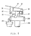
- a supporter 30 mounted on the carrier 28 is sweepable on the supporting surface about a pivot 31.
- Said supproter 30 comprises a swinging bar 32, a pushing plate 33, a stopper 34, the pushing plate 33 and the stopper 34 are integrally formed. When the supporter 30 is sweeping, it will push the pawl 29 out of the engagement with the main gear 205.
- the stopper 34 extends approximately vertically and is cooperated with a lateral surface of the carrier 28 with such a suitable distance between the stopper 34 and the carrier 28 that the stopper 34 may just abut the lateral surface of the carrier 28 when the pawl is pushed off the teeth of the main gear 205 by the pushing plate 33 so as to stop the rotation of the supporter 30.
- the upper end of the main gear 205 is formed with a closed cam surface 35.
- the cam surface facing up ard may be any smoothly curved.
- the supporter 30 is equiped with a swinging bar 32 which can sweep together with the supporter 30 with respect to the carrier 28, one end of the swinging bar 32 is pivoted mounted on the supporter 30.
- a pulling spring 36 is used to pull the swinging bar 32 which consequently pushes a cam follower 37 downwardly, so that one end of the cam follower 37 can always be kept in contact with the cam surface 35 of the main gear 205.
- the cam follower 37 is slidablly positioned in a guide hole of the carrier 28 and its two ends contact with the swinging bar 32 and the cam surface 35 of the main gear 205, respectively.
- the two ends of the cam follower 37 may be manufactured as ball-shaped or equiped with roller(s) to improve the moving ability.
- the swinging bar 32 has two functions: the first is to swing in accordance with the locus determined by the curve of the cam surface 35, so that the relative angular displacement between the spindle 207 and the hollow shaft 206 can be indicated out. The second is to produce a torque when the rotation of the swinging bar 32 is res sted, making the clutch be disengaged and the spindle stop rotating.
- an adjustable baffle 38 is arranged on the casing and is mounted on a guide post 40 of the casing.
- the baffle can not rotate and may be controlled by a knob on the control board of a fan via various transmission means, for instance, a pulling cable 221, to move along a line substantially parellel to the axis of the cam follower 37.
- a notch 39 with proper shape such as a wedge shape is formed at the suitable position on the lateral of the baffle 38. The opening of the notch only allows the free end of the swinging bar 32 to pass through, that is to say the opening of the notch should be only a little bit larger than the thickness of the swinging bar 32.
- Each sweeping angle of the fan corresponds to a crank length , and the relationship therebetween may approximately be considered as a linear function.
- the cam surface 35 should be formed with a nonlinear curve.
- a closed-loop isochronous control system has been established in this embodiment, the operation is as follows:
- the main gear 205 is driven by the motor via the worm 202, the worm gear 201, the worm gear shaft 203.
- the position of the notch 39 is set by a certain displacement of the baffle 38 which is controlled by the knob on the control board of a fan.
- a given signal is thus input to the control system.
- the value of the crank length, the adjusted object is sampled by the cam-swinging bar mechanism and is amplified by the swinging bar 32.
- the amplified value of the crank length is fedback to the baffle 38 via the free end position of the swinging bar 32.
- the baffle 38 itself is also a comparator which is capable of calculating the difference between the sampled value and the given value.
- the position of the swinging bar 32 will be so matched with the position of the notch 39 that every cycle of the swinging bar 32 will not be resisted by the notch 39.
- the free end of the swinging bar 32 will be stopped by the baffle 38 when it rotates to the baffle's position. This will make the clutch disengaged and the spindle 207 stopped.
- the planetary gear system will responds to operate, changing the crank length and the fan sweeping angle as well.
- the cam surface will drive the swinging bar 32 to swing and the free end of the swinging bar 32 to slide on the lateral edge of the baffle 38, giving new sample of the crank length to the baffle 38 to compare with the given value. Because of the continuity of the curved cam surface, the above device will finally find a sampled value which is in accordance with the given value no matter the given value is a increased one or decreased one. When this is done, the free end of the swinging bar 32 will find and pass the notch 39. Therefore the stopped spindle 207 will be released and the clutch will be engaged so that the crank length adjusting process is finished and the fan will operate with a new sweeping angle.
- the smoothly curved cam surface may be formed on the lateral of the cam.
- the cam follower 37 and the swinging bar 32 can be integrally formed and arranged horizontally.
- the baffle 38 is also arranged horizontally and with the notch 39 facing downwardly.
- One end of the cam follower, which does not contact with the cam surface, is bent upwardly. This bent part of the cam follower is of the same functions as the free end of the swinging bar 32 in above embodiment.
- the cam follower is mounted in a sleeve formed on the supporter 30, allowing the motion of the cam follower along the axis of the sleeve.
- the supporter 30 will sweep with respect to the carrier so that the pawl will be pushed away from the main gear 205.
Landscapes
- Engineering & Computer Science (AREA)
- Mechanical Engineering (AREA)
- General Engineering & Computer Science (AREA)
- Structures Of Non-Positive Displacement Pumps (AREA)
Claims (15)
- Eine Vorrichtung zur Steuerung des Schwenkwinkels eines Ventilators bestehend aus einem Gehäuse; einem Hauptantrieb bzw. zahnrad (5, 105, 205), der mit der Achswelle (3, 203), einer Getriebeschnecke (1, 201) in Eingriff steht; einer Achse (7, 107, 207) und einer hohlen Welle (6, 106, 206); wobei der Hauptantrieb (5, 105, 205), entweder auf der Achse (7, 107, 207) oder der hohlen Welle (6, 106, 206) befestigt ist; die Achse (7, 107, 207) drehbar konzentrisch innerhalb der hohlen Welle (6, 106, 206) angeordnet ist; einem umlaufenden bzw. planetär Träger (9, 209), der starr ein Planetenrad (11, 211) trägt, das um seine eigene Achse drehbar ist; einem Kurbelgriff (10, 210), der an dem Planetenrad (11, 211) befestigt ist; einer Verbindungsstange (14, 214), die mit ihrem einem Ende an dem Kurbelgriff (10, 210) angelenkt ist; einem Sonnenrad (12, 212), das in ein Ende der Achse (7, 107, 207) integriert ist und in das Planetenrad (11, 211) eingreift, dadurch gekennzeichnet, daß die Vorrichtung des weiteren Kupplungsmittel (16, 17, 23, 24, 25, 29), die zwischen der Achse (7, 107, 207) und der hohlen Welle (6, 106, 206) angeordnet sind und Stellmittel (19, 21, 121) zur Steuerung der Kupplungsmittel aufweist.
- Eine Vorrichtung nach Anspruch 1, wobei der Abstand zwischen den Achsen des Sonnenrads (12, 212) und des Planetenrads (11, 211) gleich ist mit dem Abstand zwischen den Achsen des Planetenrads (11, 211) und des Kurbelgriffs (10, 210).
- Eine Vorrichtung nach einem der Ansprüche 1 oder 2, wobei der Kurbelgriff (10, 210) mit dem Planetenrad (11, 211) integral ausgebildet ist.
- Eine Vorrichtung nach einem der vorstehenden Ansprüche, wobei die Kupplungsmittel aufweisen: eine Bremsscheibe (16), die entweder auf der Achse (7) oder der hohlen Welle (6) starr befestigt ist, wobei die Achse (7), relativ zur hohlen Welle (6) axial beweglich ist, die Bremsscheibe (16) durch ein Federmittel (17) in Reibungseingriff mit dem Hauptantrieb (5) vorgespannt ist und die Stellmittel einen steuerbaren Hebel (19) umfassen um die Bremsscheibe aus dem Eingriff mit dem Hauptantrieb (5) zu bewegen und gleichzeitig die Bremsscheibe (16) abzubremsen.
- Eine Vorrichtung nach Anspruch 4, wobei das Ende des Hebels (19) für die Zusammenarbeit mit der Bremsscheibe (16) mit einer Klemmnut (20) ausgestattet ist.
- Eine Vorrichtung entsprechend einem der Ansprüche 1 bis 3, wobei die Kupplungsmittel aufweisen: ein getriebenes Rad (23), das entweder an der Achse (107) oder der hohlen Welle (106) starr montiert ist, wobei das angetriebene Rad (23), mit dem Hauptantrieb (105) identisch ist, einem Auslösehebel (24), der schwenkbar an dem Gehäuse befestigt ist, mit einem Treibrad (25), das drehbar darauf angeordnet ist, und eine Spitze; wobei der Auslösehebel (24) durch ein Federmittel (27) vorgespannt ist, um das Treibrad (25) in Verzahnung mit beiden Rädern (23, 105) zu bringen, ein Kabel (121), das mit dem Auslösehebel (24) verbunden ist, um das Treibrad (25) zu steuern, wenn es nicht mit beiden Rädern (23, 105) in Eingriff steht und gleichzeitig das angetriebene Rad (23) durch Einlenken der Spitze des Auslösehebels (24) in die Zähne des angetriebenen Rades (23) abzubremsen.
- Eine Vorrichtung nach Anspruch 1, wobei die Kupplungsmittel eine Klinke (24, 29) und eine Ratsche (23, 205) bzw. ein Zahngesperre aufweisen.
- Eine Vorrichtung nach Anspruch 1 oder 7, wobei der Hauptantrieb (205) als eine Ratsche funktioniert.
- Eine Vorrichtung nach Anspruch 1, 7 oder 8, wobei die Stellmittel aufweisen: einen Träger (28), der entweder auf der Achse (207) oder der hohlen Welle (206) starr befestigt ist; einen Träger (30), der auf dem Träger (28) angeordnet ist und um einen vertikalen Stift im wesentlichen in einer horizontalen Ebene geschwenkt werden kann, wobei der Träger (30), eine Schiebeplatte (33) und eine Schwenkstange (32) umfasst, die Schwenkstange (32) auf dem Träger (30) befestigt ist, um einen im wesentlichen horizontalen Stift im wesentlichen in einer vertikalen Ebene drehbar ist und durch Federmittel (36) vorgespannt ist; ein Ablenkblech (38), das auf dem Gehäuse befestigt ist und zur wechselseitigen Bewegung in nur einer Richtung gesteuert wird, wobei das Ablenkblech (38), eine seitliche Kante mit einer daran ausgebildeten Aussparung bzw. Nut (39) aufweist, wobei das freie Ende der Schwenkstange (32), die Ablenkplatte (38) nur durch die Aussparung (39) passieren lassen kann, um zusammen mit dem Träger (28) zu rotieren; eine Klinke (29), die auf dem Träger (28) befestigt ist, mit der daran angrenzenden Schiebeplatte (33); eine geschlossene Nockenfläche (35), die auf dem Hauptantrieb (205) ausgebildet ist; einen Nockenstößel (37), der auf dem Träger (28) beweglich befestigt ist wobei sein eines Ende gleitfähig an der Nockenfläche (35) angrenzt und ein anderes Ende an der Schwingstange (32) angrenzt.
- Vorrichtung nach Anspruch 9, wobei der Träger (30) weiterhin umfasst: einen Stopper (34), der integral mit der Schiebeplatte (33) ausgebildet ist, wobei der Stopper (34) sich im wesentlichen vertikal erstreckt und mit einer Absperroberfläche zusammenwirkt, die auf dem Träger (28) ausgebildet ist, um die Bewegung des Trägers (30) einzugrenzen.
- Eine Vorrichtung nach Anspruch 9, wobei die Klinke (29) mit dem Hauptantrieb, der die Form einer Ratsche (205) hat, durch ein Federmittel in Eingriff vorgespannt ist.
- Eine Vorrichtung nach Anspruch 9, wobei die auf der Ablenkplatte (38) ausgebildete Aussparung (39) keilförmig ist, und die Breite der Öffnung der Aussparung geringfügig größer ist als die Dicke des freien Endes der Schwingstange (32).
- Eine Vorrichtung nach Anspruch 10, wobei der Abstand zwischen dem Stopper (34) und der abstoppenden Oberfläche groß genug ist, um der Schiebeplatte (33) zu ermöglichen die Klinke (39) aus außer Eingriff mit dem Hauptantrieb, der die Form einer Ratsche (205) hat, zu schieben.
- Eine Vorrichtung nach Anspruch 7, 8 oder 9, wobei die Eingriffsstellung der Klinke (29) mit der Ratsche (205) und die Eingriffsstellung des Hauptantriebes (205) mit der Schneckenradwelle (203) in Richtung der Dicke bzw. Stärke des Hauptantriebes (205) versetzt ist.
- Eine Vorrichtung nach Anspruch 9, wobei ein Ende des Nockenstößels (37), der gleitfähig an die Nockenfläche (35) angrenzt, mit einer Rolle ausgestattet ist, wobei die Rolle auf der Nockenoberfläche (35) rotierbar ist.
Priority Applications (2)
| Application Number | Priority Date | Filing Date | Title |
|---|---|---|---|
| EP19890301753 EP0384052B1 (de) | 1989-02-23 | 1989-02-23 | Ein Gerät zur Kontrolle des Schwenkwinkels eines Ventilators |
| DE89301753T DE68910960D1 (de) | 1989-02-23 | 1989-02-23 | Ein Gerät zur Kontrolle des Schwenkwinkels eines Ventilators. |
Applications Claiming Priority (1)
| Application Number | Priority Date | Filing Date | Title |
|---|---|---|---|
| EP19890301753 EP0384052B1 (de) | 1989-02-23 | 1989-02-23 | Ein Gerät zur Kontrolle des Schwenkwinkels eines Ventilators |
Publications (2)
| Publication Number | Publication Date |
|---|---|
| EP0384052A1 EP0384052A1 (de) | 1990-08-29 |
| EP0384052B1 true EP0384052B1 (de) | 1993-11-24 |
Family
ID=8202599
Family Applications (1)
| Application Number | Title | Priority Date | Filing Date |
|---|---|---|---|
| EP19890301753 Expired - Lifetime EP0384052B1 (de) | 1989-02-23 | 1989-02-23 | Ein Gerät zur Kontrolle des Schwenkwinkels eines Ventilators |
Country Status (2)
| Country | Link |
|---|---|
| EP (1) | EP0384052B1 (de) |
| DE (1) | DE68910960D1 (de) |
Families Citing this family (5)
| Publication number | Priority date | Publication date | Assignee | Title |
|---|---|---|---|---|
| JP6647602B1 (ja) * | 2018-10-10 | 2020-02-14 | アイリスオーヤマ株式会社 | 送風機 |
| CN110985422A (zh) * | 2019-12-15 | 2020-04-10 | 张一茗 | 风扇摇头角度控制装置 |
| CN112476487B (zh) * | 2020-11-21 | 2021-12-07 | 苏州卓罗智能科技有限公司 | 一种具有散热结构的智能机器人 |
| CN112923018A (zh) * | 2021-03-04 | 2021-06-08 | 珠海格力电器股份有限公司 | 风机装置及空调机组 |
| CN113153797B (zh) * | 2021-05-06 | 2022-10-25 | 蒋亮健 | 电风扇手调式标识摆角调节装置 |
Family Cites Families (4)
| Publication number | Priority date | Publication date | Assignee | Title |
|---|---|---|---|---|
| US1403151A (en) * | 1919-02-06 | 1922-01-10 | Diehl Mfg Co | Oscillating fan |
| US1908287A (en) * | 1930-10-06 | 1933-05-09 | Diehl Mfg Co | Electric fan |
| US2791122A (en) * | 1954-01-20 | 1957-05-07 | Singer Mfg Co | Top-controlled oscillating mechanisms for electric fans |
| GB983671A (en) * | 1962-02-26 | 1965-02-17 | Braskamp W H Nv | Table ventilator |
-
1989
- 1989-02-23 DE DE89301753T patent/DE68910960D1/de not_active Expired - Lifetime
- 1989-02-23 EP EP19890301753 patent/EP0384052B1/de not_active Expired - Lifetime
Also Published As
| Publication number | Publication date |
|---|---|
| EP0384052A1 (de) | 1990-08-29 |
| DE68910960D1 (de) | 1994-01-05 |
Similar Documents
| Publication | Publication Date | Title |
|---|---|---|
| US4290634A (en) | Electrically and manually operable locking mechanism and drive arrangement for the same | |
| US5620230A (en) | Adjustable hairdresser's chair | |
| EP0384052B1 (de) | Ein Gerät zur Kontrolle des Schwenkwinkels eines Ventilators | |
| EP0352236B1 (de) | Wahlweise hand- oder motorgesteuerte tragbare Rohrbiegemaschine mit Kupplungs- und selbsttätiger Entkupplungsvorrichtung | |
| US5217417A (en) | Device for controlling the sweeping-angle of a fan | |
| CN112738362B (zh) | 摄像装置、电子设备及电子设备的使用方法 | |
| CN112549321A (zh) | 一种钻孔用斜孔精确角度定位辅助器 | |
| JPH0788913B2 (ja) | バルブのスピンドル駆動機構 | |
| CN211209495U (zh) | 一种扭矩可调电缸 | |
| JPS5833077B2 (ja) | イドウスル ヒセツダンブツオイツテイナガサニセツダンスル ソウチ | |
| US4285453A (en) | Wire insertion apparatus, particularly for forming presses | |
| CN213594059U (zh) | 一种汽车空调电动出风口手动拨钮结构 | |
| CA1253139A (en) | Electric mixer with beater eject mechanism | |
| CN113080733A (zh) | 搅拌机 | |
| US4221136A (en) | Sewing machine and speed adjustment mechanism thereof | |
| JPH02233897A (ja) | 扇風機の首振り制御装置 | |
| CN115030910B (zh) | 摇头结构及风扇 | |
| CN222443026U (zh) | 一种冰淇淋机结构 | |
| JP2846487B2 (ja) | ミシンの上送り機構 | |
| CN116181162B (zh) | 一种电动锁体 | |
| CN220347702U (zh) | 一种单向器装配机 | |
| CN221098950U (zh) | 一种空调器室内机 | |
| JP3021590B2 (ja) | サンルーフ用駆動装置 | |
| CN216107513U (zh) | 一种针距调节机构 | |
| EP1591205A1 (de) | Einstellbarer schraubenschlüssel zur raschen anpassung der backenweite |
Legal Events
| Date | Code | Title | Description |
|---|---|---|---|
| PUAI | Public reference made under article 153(3) epc to a published international application that has entered the european phase |
Free format text: ORIGINAL CODE: 0009012 |
|
| AK | Designated contracting states |
Kind code of ref document: A1 Designated state(s): DE GB IT |
|
| 17P | Request for examination filed |
Effective date: 19901112 |
|
| 17Q | First examination report despatched |
Effective date: 19911209 |
|
| GRAA | (expected) grant |
Free format text: ORIGINAL CODE: 0009210 |
|
| AK | Designated contracting states |
Kind code of ref document: B1 Designated state(s): DE GB IT |
|
| PG25 | Lapsed in a contracting state [announced via postgrant information from national office to epo] |
Ref country code: DE Effective date: 19931124 Ref country code: IT Free format text: LAPSE BECAUSE OF FAILURE TO SUBMIT A TRANSLATION OF THE DESCRIPTION OR TO PAY THE FEE WITHIN THE PRESCRIBED TIME-LIMIT;WARNING: LAPSES OF ITALIAN PATENTS WITH EFFECTIVE DATE BEFORE 2007 MAY HAVE OCCURRED AT ANY TIME BEFORE 2007. THE CORRECT EFFECTIVE DATE MAY BE DIFFERENT FROM THE ONE RECORDED. Effective date: 19931124 |
|
| REF | Corresponds to: |
Ref document number: 68910960 Country of ref document: DE Date of ref document: 19940105 |
|
| PLBE | No opposition filed within time limit |
Free format text: ORIGINAL CODE: 0009261 |
|
| STAA | Information on the status of an ep patent application or granted ep patent |
Free format text: STATUS: NO OPPOSITION FILED WITHIN TIME LIMIT |
|
| 26N | No opposition filed | ||
| PGFP | Annual fee paid to national office [announced via postgrant information from national office to epo] |
Ref country code: GB Payment date: 20000218 Year of fee payment: 12 |
|
| PG25 | Lapsed in a contracting state [announced via postgrant information from national office to epo] |
Ref country code: GB Free format text: LAPSE BECAUSE OF NON-PAYMENT OF DUE FEES Effective date: 20010223 |
|
| GBPC | Gb: european patent ceased through non-payment of renewal fee |
Effective date: 20010223 |