EP0384885A2 - Verteiler von Einzelstücken - Google Patents
Verteiler von Einzelstücken Download PDFInfo
- Publication number
- EP0384885A2 EP0384885A2 EP90810044A EP90810044A EP0384885A2 EP 0384885 A2 EP0384885 A2 EP 0384885A2 EP 90810044 A EP90810044 A EP 90810044A EP 90810044 A EP90810044 A EP 90810044A EP 0384885 A2 EP0384885 A2 EP 0384885A2
- Authority
- EP
- European Patent Office
- Prior art keywords
- conveyor track
- conveyor
- transfer device
- distributor according
- distributor
- Prior art date
- Legal status (The legal status is an assumption and is not a legal conclusion. Google has not performed a legal analysis and makes no representation as to the accuracy of the status listed.)
- Granted
Links
- 230000001681 protective effect Effects 0.000 claims 1
- 230000033001 locomotion Effects 0.000 description 2
- 230000004888 barrier function Effects 0.000 description 1
- 230000005540 biological transmission Effects 0.000 description 1
- 235000019219 chocolate Nutrition 0.000 description 1
- 230000002441 reversible effect Effects 0.000 description 1
- 230000001360 synchronised effect Effects 0.000 description 1
Images


Classifications
-
- B—PERFORMING OPERATIONS; TRANSPORTING
- B65—CONVEYING; PACKING; STORING; HANDLING THIN OR FILAMENTARY MATERIAL
- B65G—TRANSPORT OR STORAGE DEVICES, e.g. CONVEYORS FOR LOADING OR TIPPING, SHOP CONVEYOR SYSTEMS OR PNEUMATIC TUBE CONVEYORS
- B65G47/00—Article or material-handling devices associated with conveyors; Methods employing such devices
- B65G47/74—Feeding, transfer, or discharging devices of particular kinds or types
- B65G47/84—Star-shaped wheels or devices having endless travelling belts or chains, the wheels or devices being equipped with article-engaging elements
- B65G47/846—Star-shaped wheels or wheels equipped with article-engaging elements
Definitions
- the present invention relates to a distributor of individual pieces according to the preamble of patent claim 1.
- a transfer device is provided with a plurality of suction trolleys, which are arranged around a central axis by means of arms.
- Each suction trolley is provided with a suction device and a valve tappet for controlling the vacuum, which is actuated by the single piece to be picked up, so that the suction air is released and the single piece is held in the suction device.
- the suction cups are designed to be rotatable by 90 degrees so that the individual pieces located on the conveyor belt of the feed section maintain their position when they are delivered to the conveyor belt of the receiving section.
- the known transfer device does indeed cause the individual pieces to be transferred correctly from one encoder machine to a cartoning machine, but is very complex with regard to the suction cups, which are rotatable by 90 degrees and work with vacuum.
- the present invention is therefore based on the object of creating a distributor of individual pieces with a less complex transfer device.
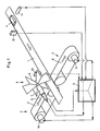
- the distributor shown in Fig. 1 has a conveyor track 1, which can be set in motion between two conveyors 2 and 3, the conveyor tracks 2 'and 3' of the conveyor 2 and 3 and the conveyor track 1 at least approximately in one plane are located.
- a single piece 4, for example a packaged chocolate bar, lies on the conveyor track 1.
- a transfer device 5 is arranged, which has an impeller 6, a servo motor 7 and one Encoder 8 comprises, which is connected to a processor or computer 9, which also supplies signals for a servo motor 10 of the conveyor 2 and for a servo motor 11 of the conveyor 3.
- a sensor 12 is arranged directly in front of the transfer device 5 in the direction of movement of the conveyor track 1; and preferably about 2 piece lengths in front of it is a second sensor 13, the processor 9 being connected to these sensors 12 and 13 as well as to a further encoder 14 synchronized with the conveyor track 1.
- the conveyors 2 and 3 and the transfer device 5 are shown with some details to show that the conveyors each have an auxiliary conveyor 15, 15 '.
- the conveyor 2 and the auxiliary conveyor 15 have a common roller 16 with four grooves or grooves, namely two with the inner diameter D and two with the inner diameter d, D being greater than d.
- Conveyors 2 and / or 3 preferably have no conveyor belts, but two round belts each, of which only one round belt 18 or 19 is visible in FIG. 2, which are inserted into the grooves with diameter D.
- auxiliary conveyor 15, 15 'each comprise two chain belts, which are inserted into the grooves with the diameter d, and of which only one chain belt 20 or 21 is visible in FIG. 2.
- These Chain belts are provided with holding links 22 and 23, which are preferably distributed at regular intervals.
- the transfer device 5 shown in FIG. 2 has an impeller with six blades, the edge of the blade 24 being in the vicinity of a single piece 4 lying on the conveyor track 1.
- the holding members 22 are outside the area defined by the round belts 18, 18 '.
- the holding links 22 according to FIG. 2 are located within the area mentioned, to indicate that both types of embodiment are possible, with instead of round and chain belts e.g. V-belts or flat belts could also be used.
- Fig. 3 several individual pieces 4 are shown both on the conveyor track or the conveyor belt 1 and on the pairs of belts 18, 18 'and 19, 19'. From the transfer device, only two wings 25, 25 'are visible in Fig. 3.
- the distance between the axis 26 of the impeller and the outer edge of a Wing 24 is slightly smaller than the distance between this axis 26 and the area determined by the round belts 18, 18 ', on which the individual pieces 4 lie.
- the wings each have a central slot 27, 27 'to create a free space for a guide rail 28 which is arranged perpendicular to the axis 26 and slightly above the individual pieces 4.
- the optional guide bar 28 is not shown in FIGS. 1 to 3. This guide bar can be straight or partially curved.
- the distributor according to FIGS. 1 to 4 now works as follows: First of all, it should be noted that the distributor can also work with only one of the conveyors 2 or 3, that the sensor 12 is omitted for some applications, and that the impeller must have at least two blades or a blade and a counterweight.
- the processor 9 can determine the position of a reference point of the conveyor track 1 at any moment by means of the signals supplied by the encoder 14.
- the processor 9 can use the signals supplied by the sensor 13 (FIG. 1) to determine when the front edge of a single piece 4 is just at the sensor 13 passes by. With this information, the processor 9 can supply the encoder 8 with signals which control the servo motor 7 in such a way that a wing 24 (FIG. 2) of the transfer device 5 pushes a single piece 4 just when it is in a centered position with respect to it on the conveyor track 2 ', so that the single piece lands on the conveyor track 2' and is held by the holding members 22.
- the processor 9 can also control the servo motor 10 in such a way that the individual pieces 4 arrive at the conveyor track 2 'at a certain cycle or at predetermined intervals.
- the sensor 12 serves to detect the position of the pieces on the feed belt or the conveyor track 1. If after switching on the distributor there are pieces between the two sensors 12 and 13 whose position is not known, they are detected by the sensor 12 and then, for example encountered on the conveyor track 3 'by rotating the impeller 6 in the other direction.
- the processor 9 can perform a so-called software shift register function as follows: As soon as the sensor 13 detects a beginning of a piece, a one is written into the register, which is currently displayed. Its address is recorded in a so-called address flag and the counter is deleted. With each cycle from the encoder 14, the counter is increased by one and the reader and writer are shifted up by one address. Registered the Sensor 13 again a piece beginning, the counter content is stored under the address that is in the address flag, the new recorder address is recorded in the address flag and the counter is deleted. After a shift register length, the reader now reads the values that the writer has written into it.
- the transfer device runs at a speed at which one revolution corresponds to the average distance between the pieces. The corresponding value is subtracted from the counter and added to the address in the address flag. The one in the shift register is now stored in this new address in the shift register. It should be noted that the impeller should rotate continuously and should not be reduced to zero speed.
- the distributor can have, for example, three proximity switches, which are used when the motors are positioned when switched on or during a reset.
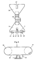
- the transfer device has an open belt drive with two rollers 30, 31, at least one pin 33 being attached to the belt 32.
- the belt drive according to FIG. 5 is arranged transversely over the conveyor track 1, preferably in such a way that the axes of the rollers 30, 31 run parallel to the conveyor track 1.
- the belt drive works in such a way that at a predetermined time the pin 33 moves the piece 4 from the center of the conveyor track 1 to the conveyor track 2 'or 3'.
- the distributor according to the invention can not only work with one of the conveyors 2 or 3, but also when the power is divided between the two conveyors.
- a storage function is also possible in that pieces that are on one of the conveyor tracks 2 'or 3' are moved via the stationary conveyor track 1 to the other conveyor track 3 'or 2'.
- the distributor is reversible, which means that the conveyor track 1 can serve not only as a feed track but also as a receiving track.
- Light barriers can serve as sensors, for example.
Landscapes
- Engineering & Computer Science (AREA)
- Mechanical Engineering (AREA)
- Attitude Control For Articles On Conveyors (AREA)
- Control Of Conveyors (AREA)
- Branching, Merging, And Special Transfer Between Conveyors (AREA)
- Feeding Of Articles To Conveyors (AREA)
- Specific Conveyance Elements (AREA)
- Intermediate Stations On Conveyors (AREA)
- Special Conveying (AREA)
Abstract
Description
- Die vorliegende Erfindung betrifft einen Verteiler von Einzelstücken gemäss dem Oberbegriff des Patentanspruchs 1.
- Aus der DE-OS 25 51 538 ist eine Vorrichtung zum Zuführen und Einlegen von Einzelstücken in die Aufnahmetaschen der Förderkette einer Kartoniermaschine bekannt. Zu diesem Zweck ist eine Uebergabevorrichtung mit einer Vielzahl von Saugerwagen vorgesehen, welche mittels Armen um eine zentrale Achse angeordnet sind. Jeder Saugerwagen ist zur Aufnahme eines Einzelstücks mit einem Sauger sowie mit einem dem Steuern des Vakuums dienenden Ventilstössel versehen, wobei dieser durch das aufzunehmende Einzelstück betätigt wird, so dass die Saugluft freigegeben und das Einzelstück im Sauger festgehalten wird. Damit die auf dem Förderband der Zufuhrstrecke befindlichen Einzelstücke bei der Abgabe auf das Förderband der Aufnahmestrecke ihre Lage beibehalten, sind die Sauger um 90 Grad drehbar ausgebildet.
- Die bekannte Uebergabevorrichtung, deren zentrale Achse senkrecht zu beiden Förderbändern angeordnet ist, bewirkt zwar eine einwandfreie Uebergabe der Einzelstücke von einer Geber maschine zu einer Kartoniermaschine, ist jedoch sehr aufwendig im Hinblick auf die Sauger, die um 90 Grad drehbar ausgebildet sind und mit Vakuum arbeiten.
- Der vorliegenden Erfindung liegt daher die Aufgabe zugrunde, einen Verteiler von Einzelstücken mit einer weniger aufwendigen Uebergabevorrichtung zu schaffen.
- Diese Aufgabe wird erfindungsgemäss durch einen Verteiler mit den im kennzeichnenden Teil des Patentanspruchs 1 angegebenen Merkmalen gelöst.
- Durch die spezielle Gestaltung des Verteilers und insbesondere der Uebergabevorrichtung, deren zentrale Achse nicht mehr senkrecht zu den beiden Förderbahnen verlaufen muss, sondern vorzugsweise parallel zur Förderbahn der Zufuhrstrecke verlaufen kann, ergibt sich eine wesentliche Vereinfachung der Uebergabevorrichtung.
- Andere vorteilhafte Ausgestaltungen der Erfindung sind in weiteren Ansprüchen angegeben.
- Die Erfindung wird nachfolgend durch Beschreibung von Ausführungsbeispielen anhand einer Zeichnung näher beschrieben. Es zeigt:
- Fig. 1 eine schematische Darstellung eines erfindungsgemässen Verteilers,
- Fig. 2 eine Seitenansicht einer Uebergabevorrichtung zwischen zwei Förderern nach der Erfindung,
- Fig. 3 eine Draufsicht einer solchen Uebergabevorrichtung,
- Fig. 4 eine Querschnittdarstellung des Flügelrades einer Uebergabevorrichtung nach einer ersten Ausführung der Erfindung,
- Fig. 5 eine schematische Seitenansicht einer weiteren Ausführung einer Uebergabevorrichtung nach der Erfindung.
- Der in Fig. 1 dargestellte Verteiler weist eine Förderbahn 1 auf, die zwischen zwei Förderern 2 und 3 in Bewegung gesetzt werden kann, wobei die Förderbahnen 2′ und 3′ der Förderer 2 bzw. 3 und die Förderbahn 1 sich zumindest angenähert in einer Ebene befinden. Auf der Förderbahn 1 liegt ein Einzelstück 4, beispielsweise ein verpackter Schokoladeriegel. Im Bereich zwischen den zwei Förderern 2 und 3, jedoch oberhalb derselben ist eine Uebergabevorrichtung 5 angeordnet, die ein Flügelrad 6, einen Servomotor 7 und einen Encoder 8 umfasst, der an einen Prozessor oder Rechner 9 angeschlossen ist, der auch Signale für einen Servomotor 10 des Förderers 2 und für einen Servomotor 11 des Förderers 3 liefert. Unmittelbar vor der Uebergabevorrichtung 5 in der Bewegungsrichtung der Förderbahn 1 ist ein Sensor 12 angeordnet; und vorzugsweise etwa 2 Stücklängen vor ihm befindet sich ein zweiter Sensor 13, wobei der Prozessor 9 sowohl an diesen Sensoren 12 und 13 als auch an einen weiteren, mit der Förderbahn 1 synchronisierten Encoder 14 angeschlossen ist.
- In Fig. 2 sind die Förderer 2 und 3 und die Uebergabevorrichtung 5 mit einigen Details dargestellt, um zu zeigen, dass die Förderer je einen Hilfsförderer 15, 15′ aufweisen. Der Förderer 2 und der Hilfsförderer 15 haben eine gemeinsame Rolle 16 mit vier Rillen oder Nuten, und zwar zwei mit dem Innendurchmesser D und zwei mit dem Innendurchmesser d, wobei D grösser als d ist. Entsprechendes gilt für eine Rolle 17 bezüglich der Förderer 3 und 15′. Die Förderer 2 und/oder 3 weisen vorzugsweise keine Förderbänder, sondern je zwei Rundriemen auf, von denen in der Fig. 2 nur je ein Rundriemen 18 bzw. 19 sichtbar ist, die in die Rillen mit dem Durchmesser D eingesetzt sind. Demgegenüber können die Hilfsförderer 15, 15′ je zwei Kettenriemen umfassen, die in die Rillen mit dem Durchmesser d eingesetzt sind, und von denen in der Fig. 2 nur je ein Kettenriemen 20 bzw. 21 sichtbar ist. Diese Kettenriemen sind mit Haltegliedern 22 bzw. 23 versehen, die vorzugsweise in regelmässigen Abständen verteilt sind. Die in Fig. 2 dargestellte Uebergabevorrichtung 5 weist ein Flügelrad mit sechs Flügeln auf, wobei die Kante des Flügels 24 sich in der Nähe eines auf der Förderbahn 1 liegenden Einzelstücks 4 befindet.
- In Fig. 3 sind die zwei Rundriemenpaare 18, 18′ und 19, 19′ des Förderers 2 bzw. 3 und zur Vereinfachung der Zeichnung nur einige Halteglieder 22, 23 ohne die Kettenriemen dargestellt.
- In der Ausführung nach Fig. 3 befinden sich die Halteglieder 22 ausserhalb der von den Rundriemen 18, 18′ bestimmten Fläche. Im Gegensatz dazu befinden sich die Halteglieder 22 nach Fig. 2 innerhalb der erwähnten Fläche, um anzudeuten, dass beide Ausführungsarten möglich sind, wobei anstelle von Rund- und Kettenriemen z.B. auch Keil- oder Flachriemen eingesetzt werden könnten. In Fig. 3 sind mehrere Einzelstücke 4 sowohl auf der Förderbahn oder dem Förderband 1 als auch auf den Riemenpaaren 18, 18′ und 19, 19′ dargestellt. Von der Uebergabevorrichtung sind in Fig. 3 nur zwei Flügel 25, 25′ sichtbar.
- Ferner ist aus Fig. 4 ersichtlich, dass der Abstand zwischen der Achse 26 des Flügelrades und der äusseren Kante eines Flügels 24 etwas kleiner als der Abstand zwischen dieser Achse 26 und der von den Rundriemen 18, 18′ bestimmten Fläche ist, auf der die Einzelstücke 4 liegen. In Fig. 4 liegen die Halteglieder 22, 22′ aussenseitig in bezug auf die Rundriemen 18, 18′. Die Flügel weisen je einen mittig verlaufenden Schlitz 27, 27′ auf, um einen freien Raum für eine Führungsleiste 28 zu schaffen, die senkrecht zur Achse 26 und etwas oberhalb der Einzelstücke 4 angeordnet ist. Zur Vereinfachung der Zeichnung ist die fakultative Führungsleiste 28 in den Figuren 1 bis 3 nicht dargestellt. Diese Führungsleiste kann geradlinig oder zum Teil gebogen sein.
- Der Verteiler nach den Figuren 1 bis 4 funktioniert nun folgendermassen:
Zunächst ist festzuhalten, dass der Verteiler auch mit nur einem der Förderer 2 oder 3 arbeiten kann, dass für einige Anwendungen der Sensor 12 entfällt, und dass das Flügelrad mindestens zwei Flügel oder einen Flügel und ein Gegengewicht aufweisen muss. - Durch die vom Encoder 14 gelieferten Signale kann der Prozessor 9 die Lage eines Referenzpunktes der Förderbahn 1 in jedem Moment bestimmen. Durch die vom Sensor 13 (Fig. 1) gelieferten Signale kann der Prozessor 9 bestimmen, wann die vordere Kante eines Einzelstücks 4 gerade beim Sensor 13 vorbeigeht. Mit diesen Angaben kann der Prozessor 9 dem Encoder 8 Signale liefern, die den Servomotor 7 derart steuert, dass ein Flügel 24 (Fig. 2) der Uebergabevorrichtung 5 gerade dann einem Einzelstück 4 einen Stoss gibt, wenn es sich in einer zentrierten Lage in bezug auf die Förderbahn 2′ befindet, so dass das Einzelstück auf der Förderbahn 2′ landet und von den Haltegliedern 22 gehalten wird. Dabei kann der Prozessor 9 auch den Servomotor 10 derart steuern, dass die Einzelstücke 4 in einem bestimmten Takt oder in vorbestimmten Abständen auf die Förderbahn 2′ gelangen. Der Sensor 12 dient zur Erfassung der Position der Stücke auf dem Zufuhrband oder der Förderbahn 1. Wenn nach Einschalten des Verteilers Stücke zwischen den zwei Sensoren 12 und 13 liegen, deren Position man nicht kennt, so werden sie durch den Sensor 12 erfasst und dann beispielsweise auf die Förderbahn 3′ gestossen, indem das Flügelrad 6 in die andere Richtung gedreht wird.
- Der Prozessor 9 kann eine sogenannte Software-Schieberegister-Funktion wie folgt ausüben:
Sobald der Sensor 13 einen Stückanfang detektiert, wird eine Eins in das Register eingeschrieben, das momentan angezeigt wird. Seine Adresse wird in einem sogenannten Adress-Merker festgehalten und der Zähler gelöscht. Bei jedem Takt vom Encoder 14 wird der Zähler um eins erhöht und Leser und Schreiber um eine Adresse hinaufgeschoben. Registriert der Sensor 13 erneut einen Stückanfang, so wird der Zählerinhalt unter diejenige Adresse gespeichert, die im Adress-Merker steht, die neue Schreiberadresse wird im Adress-Merker festgehalten und der Zähler gelöscht. Der Leser liest nun nach einer Schieberegisterlänge die Werte, die der Schreiber hineingeschrieben hat. Liest der Leser eine Null, so wird nichts unternommen, liest er eine Zahl grösser als eins, so wird dies als ein Abstand zwischen zwei Stücken aufgefasst, woraus eine Uebersetzung für das elektronische Getriebe gerechnet werden muss. Liest der Leser eine Eins, so bedeutet das, dass immer noch kein neues Stück beim Sensor 13 angekommen ist. In diesem Fall läuft die Uebergabevorrichtung mit einer Geschwindigkeit, bei der eine Umdrehung dem mittleren Abstand zwischen den Stücken entspricht. Der entsprechende Wert wird vom Zähler subtrahiert und zur Adresse im Adress-Merker addiert. Die Eins im Schieberegister wird nun unter dieser neuen Adresse im Schieberegister gespeichert. Dabei muss bemerkt werden, dass das Flügelrad kontinuierlich drehen und nicht auf Geschwindigkeit null reduziert werden soll. - Der Verteiler kann beispielsweise drei Annäherungsschalter aufweisen, die bei der Positionierung der Motoren beim Einschalten oder bei einem Reset gebraucht werden.
- Die Uebergabevorrichtung nach Fig. 5 weist einen offenen Riementrieb mit zwei Rollen 30, 31 auf, wobei am Riemen 32 mindestens ein Stift 33 befestigt ist. Der Riementrieb nach Fig. 5 wird quer über die Förderbahn 1 angeordnet, vorzugsweise derart, dass die Achsen der Rollen 30, 31 parallel zur Förderbahn 1 verlaufen. Der Riementrieb funktioniert in der Weise, dass in einem vorbestimmten Zeitpunkt der Stift 33 das Stück 4 von der Mitte der Förderbahn 1 auf die Förderbahn 2′ oder 3′ verschiebt.
- Der erfindungsgemässe Verteiler kann nicht nur mit einem der Förderer 2 oder 3, sondern auch bei einer Leistungsaufteilung auf beide Förderer arbeiten.
- Dabei ist auch eine Speicherfunktion möglich, indem Stücke, die sich auf einer der Förderbahnen 2′ oder 3′ befinden, über die stillstehende Förderbahn 1 auf die andere Förderbahn 3′ bzw. 2′ versetzt werden.
- Der Verteiler ist reversibel, das heisst, die Förderbahn 1 kann nicht nur als Zufuhrbahn, sondern auch als Aufnahmebahn dienen.
- Als Sensoren können beispielsweise Lichtschranken dienen.
Claims (10)
Applications Claiming Priority (2)
| Application Number | Priority Date | Filing Date | Title |
|---|---|---|---|
| CH606/89 | 1989-02-20 | ||
| CH60689 | 1989-02-20 |
Publications (3)
| Publication Number | Publication Date |
|---|---|
| EP0384885A2 true EP0384885A2 (de) | 1990-08-29 |
| EP0384885A3 EP0384885A3 (de) | 1991-01-09 |
| EP0384885B1 EP0384885B1 (de) | 1994-07-06 |
Family
ID=4190891
Family Applications (1)
| Application Number | Title | Priority Date | Filing Date |
|---|---|---|---|
| EP90810044A Expired - Lifetime EP0384885B1 (de) | 1989-02-20 | 1990-01-19 | Verteiler von Einzelstücken |
Country Status (5)
| Country | Link |
|---|---|
| US (1) | US5052542A (de) |
| EP (1) | EP0384885B1 (de) |
| JP (1) | JPH02233416A (de) |
| DE (1) | DE59006330D1 (de) |
| ES (1) | ES2055393T3 (de) |
Cited By (16)
| Publication number | Priority date | Publication date | Assignee | Title |
|---|---|---|---|---|
| WO1992018259A1 (en) * | 1991-04-15 | 1992-10-29 | Lorillard Tobacco Company | Sortation system for cigarette packs |
| EP0619252A3 (de) * | 1993-04-06 | 1995-01-11 | Santrade Ltd | Fördersystem mit einer Waren-Abgabevorrichtung. |
| WO1996032207A1 (en) * | 1995-04-13 | 1996-10-17 | 3M Australia Pty. Limited | Sorting device and method |
| WO1999010113A1 (de) * | 1997-08-22 | 1999-03-04 | select Ingenieurgesellschaft für Optoelektronik, Bilderkennung und Qualitätsprüfung mbH | Einrichtung zu einer merkmalsbezogenen sortierung von produkten und verfahren zu deren betrieb |
| DE19851780A1 (de) * | 1998-11-10 | 2000-05-11 | Will E C H Gmbh & Co | Vorrichtung zum Ausschleusen von Blattlagen aus einer Förderlinie |
| WO2001072614A1 (en) * | 2000-03-31 | 2001-10-04 | Tomra Systems Asa | Apparatuses for the conveying, lifting and sorting of articles |
| WO2006043834A3 (en) * | 2004-10-18 | 2006-05-26 | Foodcap Int Ltd | Apparatus and methods for processing and distribution of perishable food products |
| EP1947617A1 (de) | 2005-01-25 | 2008-07-23 | Tomra Systems ASA | Markensystem zur Installation in einem umgekehrten Verkaufsautomaten |
| RU2377173C2 (ru) * | 2004-11-30 | 2009-12-27 | Тетра Лаваль Холдингз Энд Файнэнс С.А. | Устройство для удаления предметов, перемещаемых на транспортере |
| US8317052B2 (en) | 2004-10-15 | 2012-11-27 | Foodcap International Limited | Container, lid and clip therefor |
| CN102897520A (zh) * | 2012-10-15 | 2013-01-30 | 江苏圆通农机科技有限公司 | 一种刮板拨料器 |
| CN103552836A (zh) * | 2013-10-21 | 2014-02-05 | 江苏永钢集团有限公司 | 一种窑粉灰生产装置 |
| US9097452B2 (en) | 2004-10-15 | 2015-08-04 | Foodcap International Limited | Methods and apparatus for thermal regulation of perishable products |
| US9950835B2 (en) | 2004-07-20 | 2018-04-24 | Foodcap International Limited | Product distribution methods and apparatus |
| FR3082127A1 (fr) * | 2018-06-12 | 2019-12-13 | Protection-Decoration-Conditionnement - P.D.C. Europe | Installation de selection d'objets defilant sur une ligne de transfert |
| CN113213061A (zh) * | 2021-05-13 | 2021-08-06 | 湖北瑞佳不锈钢有限公司 | 不锈钢壶体传输装置 |
Families Citing this family (25)
| Publication number | Priority date | Publication date | Assignee | Title |
|---|---|---|---|---|
| DE19542846A1 (de) * | 1995-11-17 | 1997-05-22 | Spuehl Ag | Federtransporteinrichtung mit Servo-Antrieb |
| EP0904854B1 (de) * | 1997-09-15 | 2002-11-13 | Siemens Aktiengesellschaft | Einrichtung zum Sortieren von Stückgütern |
| DE19827235C1 (de) | 1998-06-18 | 2000-02-10 | Bell & Howell Co | Postbearbeitungsmaschine |
| US6264042B1 (en) * | 1999-11-15 | 2001-07-24 | United Parcel Service Of America, Inc. | Bilateral sorter |
| CA2302095C (en) * | 2000-03-24 | 2005-06-14 | Gemofor Inc. | A lumber transfer system |
| DE50206687D1 (de) * | 2002-11-29 | 2006-06-08 | Mueller Martini Holding Ag | Einrichtung zur Herstellung eines gebundenen Druckerzeugnisses |
| DE502004005643D1 (de) * | 2004-01-28 | 2008-01-17 | Will E C H Gmbh & Co | Verfahren und Anordnung sowie Vorrichtung zum Quertransport von Riesen |
| SE527834C2 (sv) * | 2004-11-10 | 2006-06-13 | Norden Pac Dev Ab | Anordning och förfarande för kartoneringsmaskin |
| MXPA05009225A (es) * | 2005-08-30 | 2007-02-27 | Grupo Bimbo Sa De Cv | Alimentador automatico de platos y/o moldes de productos de pasteleria al tren de formado. |
| NL1030192C2 (nl) * | 2005-10-14 | 2007-04-17 | Stork Townsend Bv | Inrichting en werkwijze voor het overzetten van langgerekte voedselproducten. |
| DE102012003604B4 (de) * | 2012-02-21 | 2025-04-30 | Müller Martini Holding AG | Vorrichtung zum Zuführen von Buchblocks in den Einfuhrkanal einer Weiterverarbeitungseinrichtung |
| US9327914B1 (en) * | 2013-08-22 | 2016-05-03 | Millard Manufacturing Corp. | Rotary sweep arm system |
| JP6309305B2 (ja) * | 2014-02-26 | 2018-04-11 | 大和製衡株式会社 | 選別装置 |
| CN105415871A (zh) * | 2015-11-27 | 2016-03-23 | 荣昌精密机械(苏州)有限公司 | 一种印刷流水线机构 |
| GB201703134D0 (en) * | 2017-02-27 | 2017-04-12 | Beers Uk Ltd | Dispensing apparatus |
| JP6930720B2 (ja) * | 2017-04-21 | 2021-09-01 | 一壽 大月 | 新型フリートレイ式選果設備 |
| CN108177962A (zh) * | 2017-12-08 | 2018-06-19 | 桐乡胜辉精密机械有限公司 | 一种工件送料机构 |
| AU2019368359B2 (en) * | 2018-10-25 | 2025-10-02 | And Y Knot Innovation And Sales Inc. | Stacking and packaging device |
| CN109592308A (zh) * | 2018-11-30 | 2019-04-09 | 河南易成新能源股份有限公司 | 机加自动送料装置及方法 |
| FR3098208B1 (fr) * | 2019-07-01 | 2023-10-27 | Semso | Dispositif de convoyage de produits filiformes a grande vitesse et procede de mise en oeuvre |
| JP7473387B2 (ja) * | 2020-05-12 | 2024-04-23 | 株式会社前川製作所 | ワーク移送装置 |
| CN112811148B (zh) * | 2020-12-29 | 2022-06-21 | 江苏华工激光科技有限公司 | 一种分料装置 |
| WO2023015385A1 (en) | 2021-08-11 | 2023-02-16 | And Y Knot Innovation And Sales Inc. | Device and conveyance system for packaging elongated items |
| DE102021123023A1 (de) | 2021-09-06 | 2023-03-09 | Wipotec Gmbh | Sortiervorrichtung |
| CN116119301B (zh) * | 2022-12-30 | 2023-09-19 | 徐州华睿炭材料科技有限公司 | 一种活性炭包的加工设备 |
Family Cites Families (20)
| Publication number | Priority date | Publication date | Assignee | Title |
|---|---|---|---|---|
| US2049112A (en) * | 1930-07-07 | 1936-07-28 | Newton Steel Company | Sheet feeding apparatus |
| AT123451B (de) * | 1930-07-19 | 1931-06-25 | Friedrich Ing Lerner | Vorrichtung zum Sondern und geordneten Ablegen von Zigaretten an Zigarettenstrangmaschinen. |
| FR914140A (fr) * | 1944-10-31 | 1946-09-30 | Dispositif pour le chargement d'une trémie ou d'un autre organe comprenant une cavité à remplir | |
| US2981410A (en) * | 1957-02-05 | 1961-04-25 | Filper Corp | Apparatus for sorting pit carrying drupe halves from pit free drupe halves |
| US2957572A (en) * | 1957-05-02 | 1960-10-25 | Ferro Corp | Multiple strand conveyor |
| US3071239A (en) * | 1958-10-28 | 1963-01-01 | Stewart Warner Corp | Conveyor unloading mechanism |
| US3246733A (en) * | 1962-08-22 | 1966-04-19 | Fmc Corp | Article handling mechanism |
| US3363741A (en) * | 1966-09-21 | 1968-01-16 | Owens Illinois Inc | Article conveying apparatus |
| US3515254A (en) * | 1968-08-27 | 1970-06-02 | Leo A Gary | Conveyor system having computer for finding the centers of objects being conveyed |
| US3701407A (en) * | 1971-02-02 | 1972-10-31 | Emhart Corp | Glassware transfer mechanism |
| DE2551538A1 (de) * | 1975-11-17 | 1977-05-26 | Karlsruhe Augsburg Iweka | Uebergabevorrichtung fuer leicht deformierbare verpackungsgueter |
| US4057138A (en) * | 1976-02-05 | 1977-11-08 | Wisconsin Bridge & Iron Co. | Apparatus for routing logs |
| US4216854A (en) * | 1978-07-13 | 1980-08-12 | Avon Products, Inc. | Feeding apparatus with engaged/disengaged transport mechanism |
| US4356908A (en) * | 1979-05-25 | 1982-11-02 | The Mead Corporation | Method and apparatus for aligning and separating containers of diverse shapes |
| SE8100247L (sv) * | 1981-01-19 | 1982-07-20 | Tetra Pak Int | Sett och anordning for matning av foremal |
| US4765940A (en) * | 1984-09-21 | 1988-08-23 | American Technical Industries, Inc. | Method of transporting and forming tapered ends on piquets |
| US4635786A (en) * | 1985-01-11 | 1987-01-13 | Hershey Foods Corporation | Orientation section of packing apparatus |
| US4771877A (en) * | 1987-05-05 | 1988-09-20 | H. J. Langen & Sons Limited | Load spacing conveyor system |
| JPS6456226A (en) * | 1987-08-25 | 1989-03-03 | Mazda Motor | Vehicle ventilation device |
| US4832178A (en) * | 1988-05-12 | 1989-05-23 | Apv Douglas Machine Corporation | Container metering device |
-
1989
- 1989-12-29 JP JP1345031A patent/JPH02233416A/ja active Pending
-
1990
- 1990-01-19 ES ES90810044T patent/ES2055393T3/es not_active Expired - Lifetime
- 1990-01-19 DE DE59006330T patent/DE59006330D1/de not_active Expired - Fee Related
- 1990-01-19 EP EP90810044A patent/EP0384885B1/de not_active Expired - Lifetime
- 1990-02-20 US US07/481,593 patent/US5052542A/en not_active Expired - Fee Related
Cited By (24)
| Publication number | Priority date | Publication date | Assignee | Title |
|---|---|---|---|---|
| WO1992018259A1 (en) * | 1991-04-15 | 1992-10-29 | Lorillard Tobacco Company | Sortation system for cigarette packs |
| EP0619252A3 (de) * | 1993-04-06 | 1995-01-11 | Santrade Ltd | Fördersystem mit einer Waren-Abgabevorrichtung. |
| WO1996032207A1 (en) * | 1995-04-13 | 1996-10-17 | 3M Australia Pty. Limited | Sorting device and method |
| US6444936B1 (en) | 1997-08-22 | 2002-09-03 | Select Ingenieurgesellschaft Fuer Optoelektronik Bilderkennung Und Qualitaetspruefung Mbh | Device for sorting products depending on measured parameter, and method for operating same |
| WO1999010113A1 (de) * | 1997-08-22 | 1999-03-04 | select Ingenieurgesellschaft für Optoelektronik, Bilderkennung und Qualitätsprüfung mbH | Einrichtung zu einer merkmalsbezogenen sortierung von produkten und verfahren zu deren betrieb |
| DE19851780A1 (de) * | 1998-11-10 | 2000-05-11 | Will E C H Gmbh & Co | Vorrichtung zum Ausschleusen von Blattlagen aus einer Förderlinie |
| WO2001072614A1 (en) * | 2000-03-31 | 2001-10-04 | Tomra Systems Asa | Apparatuses for the conveying, lifting and sorting of articles |
| US6736253B2 (en) | 2000-03-31 | 2004-05-18 | Tomra Systems Asa | Apparatuses for the conveying, lifting and sorting of articles |
| US9950835B2 (en) | 2004-07-20 | 2018-04-24 | Foodcap International Limited | Product distribution methods and apparatus |
| US9097452B2 (en) | 2004-10-15 | 2015-08-04 | Foodcap International Limited | Methods and apparatus for thermal regulation of perishable products |
| US8317052B2 (en) | 2004-10-15 | 2012-11-27 | Foodcap International Limited | Container, lid and clip therefor |
| WO2006043834A3 (en) * | 2004-10-18 | 2006-05-26 | Foodcap Int Ltd | Apparatus and methods for processing and distribution of perishable food products |
| RU2377173C2 (ru) * | 2004-11-30 | 2009-12-27 | Тетра Лаваль Холдингз Энд Файнэнс С.А. | Устройство для удаления предметов, перемещаемых на транспортере |
| EP1947618A1 (de) | 2005-01-25 | 2008-07-23 | Tomra Systems ASA | Treibervorrichtung in einem Rücknahmeautomat |
| EP1947616A1 (de) | 2005-01-25 | 2008-07-23 | Tomra Systems ASA | Sicherheitsvorrichtung zum Steuern des Betriebs der Funktionsausrüstung mit beweglichen Teilen |
| EP1947613A1 (de) | 2005-01-25 | 2008-07-23 | Tomra Systems ASA | Drehförderband für Pfandgegenstände |
| EP1947615A1 (de) | 2005-01-25 | 2008-07-23 | Tomra Systems ASA | Vorrichtung für Kameraansicht eines Objekts |
| EP1947614A1 (de) | 2005-01-25 | 2008-07-23 | Tomra Systems ASA | Förderbandmittel für zurücksendbare Elemente |
| EP1947617A1 (de) | 2005-01-25 | 2008-07-23 | Tomra Systems ASA | Markensystem zur Installation in einem umgekehrten Verkaufsautomaten |
| EP3499471A1 (de) | 2005-01-25 | 2019-06-19 | Tomra Systems ASA | Mittel in rücknahmeautomaten zum aufnehmen, handhaben, sortieren und aufbewahren von rückgabeartikeln oder -objekten |
| CN102897520A (zh) * | 2012-10-15 | 2013-01-30 | 江苏圆通农机科技有限公司 | 一种刮板拨料器 |
| CN103552836A (zh) * | 2013-10-21 | 2014-02-05 | 江苏永钢集团有限公司 | 一种窑粉灰生产装置 |
| FR3082127A1 (fr) * | 2018-06-12 | 2019-12-13 | Protection-Decoration-Conditionnement - P.D.C. Europe | Installation de selection d'objets defilant sur une ligne de transfert |
| CN113213061A (zh) * | 2021-05-13 | 2021-08-06 | 湖北瑞佳不锈钢有限公司 | 不锈钢壶体传输装置 |
Also Published As
| Publication number | Publication date |
|---|---|
| JPH02233416A (ja) | 1990-09-17 |
| ES2055393T3 (es) | 1994-08-16 |
| EP0384885B1 (de) | 1994-07-06 |
| US5052542A (en) | 1991-10-01 |
| EP0384885A3 (de) | 1991-01-09 |
| DE59006330D1 (de) | 1994-08-11 |
Similar Documents
| Publication | Publication Date | Title |
|---|---|---|
| EP0384885B1 (de) | Verteiler von Einzelstücken | |
| DE69806144T2 (de) | Intelligente hochgeschwindigkeits-ablenkvorrichtung für sortierförderer | |
| DE2358185C2 (de) | Sortiergerät mit Vereinzelungsbahn und Sortierbahn | |
| DE69804641T2 (de) | Hochgeschwindigkeits-automatische-sortiervorrichtung | |
| DE3883681T2 (de) | Verfahren und Anordnung zum Vereinzeln von Gegenständen auf einem Fördersystem. | |
| DE3248788C2 (de) | Vorrichtung zum Drehen eines Gegenstandes um einen gegebenen Winkel um eine vertikale Achse | |
| DE69200669T2 (de) | Vorrichtung zum setzen von gegenständen, insbesondere von gefüllten beuteln, in einer schrägrückwärts überlappenden reihe. | |
| EP1846309B1 (de) | Vorrichtung und verfahren zum sortieren von ungeordneten behätern in einem kommissioniersystem | |
| DE602004011057T2 (de) | Sortiervorrichtung | |
| DE69001317T2 (de) | Automatischer hoch- und niedergeschwindigkeits-sortierfoerderer. | |
| DE68910786T2 (de) | System zum Anordnen in gleichen Abständen und zum Überführen von Gegenständen von einem ersten auf einen zweiten Förderer. | |
| DE2262556A1 (de) | Vorrichtung zur pruefung von ampullen | |
| DE3915217A1 (de) | Verfahren und vorrichtung zum sortieren von gegenstaenden | |
| EP3225571B1 (de) | Fördervorrichtung zur beförderung von hängenden gegenständen | |
| DE2803884A1 (de) | Einrichtung zur abgabe und verteilung von gegenstaenden | |
| EP0885821A1 (de) | Vorrichtung zum Ausrichten von im Grundriss annähernd rechteckigen Produkten | |
| DE2752193C2 (de) | Transportvorrichtung für Serienerzeugnisse innerhalb einer Wägevorrichtung | |
| DE2261463A1 (de) | Maschine zum schrittweisen zufuehren einer serie von behaeltern zwischen eine anzahl von stationen | |
| DD141901A5 (de) | Vorrichtung zum quertransport laengsbewegter zylindrischer,staebchenfoermiger objekte | |
| EP4313810B1 (de) | Vorrichtung und verfahren zur erzeugung von abständen zwischen einzelnen förderguteinheiten bei gleichzeitigem transport der förderguteinheiten | |
| EP1739036B1 (de) | Vorrichtung zum Fördern und Drehen von Gegenständen | |
| EP3802382B1 (de) | Fördereinrichtung und verfahren zum fördern von tampon-applikatoren | |
| DE1288016B (de) | ||
| DE3137676C2 (de) | ||
| DE69120871T2 (de) | Einrichtung zum Sortieren von Produkten für Verpackungs- oder Kartoniermaschinen |
Legal Events
| Date | Code | Title | Description |
|---|---|---|---|
| PUAI | Public reference made under article 153(3) epc to a published international application that has entered the european phase |
Free format text: ORIGINAL CODE: 0009012 |
|
| AK | Designated contracting states |
Kind code of ref document: A2 Designated state(s): CH DE ES FR GB IT LI NL |
|
| PUAL | Search report despatched |
Free format text: ORIGINAL CODE: 0009013 |
|
| AK | Designated contracting states |
Kind code of ref document: A3 Designated state(s): CH DE ES FR GB IT LI NL |
|
| 17P | Request for examination filed |
Effective date: 19910412 |
|
| 17Q | First examination report despatched |
Effective date: 19920430 |
|
| GRAA | (expected) grant |
Free format text: ORIGINAL CODE: 0009210 |
|
| AK | Designated contracting states |
Kind code of ref document: B1 Designated state(s): CH DE ES FR GB IT LI NL |
|
| GBT | Gb: translation of ep patent filed (gb section 77(6)(a)/1977) |
Effective date: 19940704 |
|
| REF | Corresponds to: |
Ref document number: 59006330 Country of ref document: DE Date of ref document: 19940811 |
|
| REG | Reference to a national code |
Ref country code: ES Ref legal event code: FG2A Ref document number: 2055393 Country of ref document: ES Kind code of ref document: T3 |
|
| ITF | It: translation for a ep patent filed | ||
| ET | Fr: translation filed | ||
| PLBE | No opposition filed within time limit |
Free format text: ORIGINAL CODE: 0009261 |
|
| STAA | Information on the status of an ep patent application or granted ep patent |
Free format text: STATUS: NO OPPOSITION FILED WITHIN TIME LIMIT |
|
| 26N | No opposition filed | ||
| PGFP | Annual fee paid to national office [announced via postgrant information from national office to epo] |
Ref country code: CH Payment date: 19960105 Year of fee payment: 7 |
|
| PGFP | Annual fee paid to national office [announced via postgrant information from national office to epo] |
Ref country code: FR Payment date: 19961209 Year of fee payment: 8 |
|
| PGFP | Annual fee paid to national office [announced via postgrant information from national office to epo] |
Ref country code: ES Payment date: 19970116 Year of fee payment: 8 |
|
| PG25 | Lapsed in a contracting state [announced via postgrant information from national office to epo] |
Ref country code: LI Effective date: 19970131 Ref country code: CH Effective date: 19970131 |
|
| REG | Reference to a national code |
Ref country code: CH Ref legal event code: PL |
|
| PGFP | Annual fee paid to national office [announced via postgrant information from national office to epo] |
Ref country code: GB Payment date: 19971218 Year of fee payment: 9 |
|
| PGFP | Annual fee paid to national office [announced via postgrant information from national office to epo] |
Ref country code: DE Payment date: 19971222 Year of fee payment: 9 |
|
| PG25 | Lapsed in a contracting state [announced via postgrant information from national office to epo] |
Ref country code: ES Free format text: LAPSE BECAUSE OF NON-PAYMENT OF DUE FEES Effective date: 19980120 |
|
| PGFP | Annual fee paid to national office [announced via postgrant information from national office to epo] |
Ref country code: NL Payment date: 19980130 Year of fee payment: 9 |
|
| PG25 | Lapsed in a contracting state [announced via postgrant information from national office to epo] |
Ref country code: FR Free format text: THE PATENT HAS BEEN ANNULLED BY A DECISION OF A NATIONAL AUTHORITY Effective date: 19980131 |
|
| REG | Reference to a national code |
Ref country code: FR Ref legal event code: ST |
|
| PG25 | Lapsed in a contracting state [announced via postgrant information from national office to epo] |
Ref country code: GB Free format text: LAPSE BECAUSE OF NON-PAYMENT OF DUE FEES Effective date: 19990119 |
|
| PG25 | Lapsed in a contracting state [announced via postgrant information from national office to epo] |
Ref country code: NL Free format text: LAPSE BECAUSE OF NON-PAYMENT OF DUE FEES Effective date: 19990801 |
|
| GBPC | Gb: european patent ceased through non-payment of renewal fee |
Effective date: 19990119 |
|
| PG25 | Lapsed in a contracting state [announced via postgrant information from national office to epo] |
Ref country code: DE Free format text: LAPSE BECAUSE OF NON-PAYMENT OF DUE FEES Effective date: 19991103 |
|
| REG | Reference to a national code |
Ref country code: ES Ref legal event code: FD2A Effective date: 20010503 |
|
| PG25 | Lapsed in a contracting state [announced via postgrant information from national office to epo] |
Ref country code: IT Free format text: LAPSE BECAUSE OF NON-PAYMENT OF DUE FEES;WARNING: LAPSES OF ITALIAN PATENTS WITH EFFECTIVE DATE BEFORE 2007 MAY HAVE OCCURRED AT ANY TIME BEFORE 2007. THE CORRECT EFFECTIVE DATE MAY BE DIFFERENT FROM THE ONE RECORDED. Effective date: 20050119 |