EP0384944A1 - Power generation system with use of fuel cell - Google Patents
Power generation system with use of fuel cell Download PDFInfo
- Publication number
- EP0384944A1 EP0384944A1 EP89109529A EP89109529A EP0384944A1 EP 0384944 A1 EP0384944 A1 EP 0384944A1 EP 89109529 A EP89109529 A EP 89109529A EP 89109529 A EP89109529 A EP 89109529A EP 0384944 A1 EP0384944 A1 EP 0384944A1
- Authority
- EP
- European Patent Office
- Prior art keywords
- reforming
- gas
- plate
- passages
- power generation
- Prior art date
- Legal status (The legal status is an assumption and is not a legal conclusion. Google has not performed a legal analysis and makes no representation as to the accuracy of the status listed.)
- Granted
Links
Images



Classifications
-
- B—PERFORMING OPERATIONS; TRANSPORTING
- B01—PHYSICAL OR CHEMICAL PROCESSES OR APPARATUS IN GENERAL
- B01J—CHEMICAL OR PHYSICAL PROCESSES, e.g. CATALYSIS OR COLLOID CHEMISTRY; THEIR RELEVANT APPARATUS
- B01J19/00—Chemical, physical or physico-chemical processes in general; Their relevant apparatus
- B01J19/24—Stationary reactors without moving elements inside
- B01J19/248—Reactors comprising multiple separated flow channels
- B01J19/249—Plate-type reactors
-
- C—CHEMISTRY; METALLURGY
- C01—INORGANIC CHEMISTRY
- C01B—NON-METALLIC ELEMENTS; COMPOUNDS THEREOF; METALLOIDS OR COMPOUNDS THEREOF NOT COVERED BY SUBCLASS C01C
- C01B3/00—Hydrogen; Gaseous mixtures containing hydrogen; Separation of hydrogen from mixtures containing it; Purification of hydrogen; Reversible storage of hydrogen
- C01B3/02—Production of hydrogen; Production of gaseous mixtures containing hydrogen
- C01B3/32—Production of hydrogen; Production of gaseous mixtures containing hydrogen by reaction of gaseous or liquid organic compounds with gasifying agents, e.g. water, carbon dioxide or air
- C01B3/34—Production of hydrogen; Production of gaseous mixtures containing hydrogen by reaction of gaseous or liquid organic compounds with gasifying agents, e.g. water, carbon dioxide or air by reaction of hydrocarbons with gasifying agents
- C01B3/38—Production of hydrogen; Production of gaseous mixtures containing hydrogen by reaction of gaseous or liquid organic compounds with gasifying agents, e.g. water, carbon dioxide or air by reaction of hydrocarbons with gasifying agents using catalysts
-
- H—ELECTRICITY
- H01—ELECTRIC ELEMENTS
- H01M—PROCESSES OR MEANS, e.g. BATTERIES, FOR THE DIRECT CONVERSION OF CHEMICAL ENERGY INTO ELECTRICAL ENERGY
- H01M8/00—Fuel cells; Manufacture thereof
- H01M8/02—Details
- H01M8/0202—Collectors; Separators, e.g. bipolar separators; Interconnectors
- H01M8/0258—Collectors; Separators, e.g. bipolar separators; Interconnectors characterised by the configuration of channels, e.g. by the flow field of the reactant or coolant
-
- H—ELECTRICITY
- H01—ELECTRIC ELEMENTS
- H01M—PROCESSES OR MEANS, e.g. BATTERIES, FOR THE DIRECT CONVERSION OF CHEMICAL ENERGY INTO ELECTRICAL ENERGY
- H01M8/00—Fuel cells; Manufacture thereof
- H01M8/02—Details
- H01M8/0202—Collectors; Separators, e.g. bipolar separators; Interconnectors
- H01M8/0267—Collectors; Separators, e.g. bipolar separators; Interconnectors having heating or cooling means, e.g. heaters or coolant flow channels
-
- H—ELECTRICITY
- H01—ELECTRIC ELEMENTS
- H01M—PROCESSES OR MEANS, e.g. BATTERIES, FOR THE DIRECT CONVERSION OF CHEMICAL ENERGY INTO ELECTRICAL ENERGY
- H01M8/00—Fuel cells; Manufacture thereof
- H01M8/06—Combination of fuel cells with means for production of reactants or for treatment of residues
- H01M8/0606—Combination of fuel cells with means for production of reactants or for treatment of residues with means for production of gaseous reactants
- H01M8/0612—Combination of fuel cells with means for production of reactants or for treatment of residues with means for production of gaseous reactants from carbon-containing material
- H01M8/0625—Combination of fuel cells with means for production of reactants or for treatment of residues with means for production of gaseous reactants from carbon-containing material in a modular combined reactor/fuel cell structure
-
- H—ELECTRICITY
- H01—ELECTRIC ELEMENTS
- H01M—PROCESSES OR MEANS, e.g. BATTERIES, FOR THE DIRECT CONVERSION OF CHEMICAL ENERGY INTO ELECTRICAL ENERGY
- H01M8/00—Fuel cells; Manufacture thereof
- H01M8/24—Grouping of fuel cells, e.g. stacking of fuel cells
- H01M8/241—Grouping of fuel cells, e.g. stacking of fuel cells with solid or matrix-supported electrolytes
- H01M8/244—Grouping of fuel cells, e.g. stacking of fuel cells with solid or matrix-supported electrolytes with matrix-supported molten electrolyte
-
- H—ELECTRICITY
- H01—ELECTRIC ELEMENTS
- H01M—PROCESSES OR MEANS, e.g. BATTERIES, FOR THE DIRECT CONVERSION OF CHEMICAL ENERGY INTO ELECTRICAL ENERGY
- H01M8/00—Fuel cells; Manufacture thereof
- H01M8/24—Grouping of fuel cells, e.g. stacking of fuel cells
- H01M8/2457—Grouping of fuel cells, e.g. stacking of fuel cells with both reactants being gaseous or vaporised
-
- H—ELECTRICITY
- H01—ELECTRIC ELEMENTS
- H01M—PROCESSES OR MEANS, e.g. BATTERIES, FOR THE DIRECT CONVERSION OF CHEMICAL ENERGY INTO ELECTRICAL ENERGY
- H01M8/00—Fuel cells; Manufacture thereof
- H01M8/24—Grouping of fuel cells, e.g. stacking of fuel cells
- H01M8/2465—Details of groupings of fuel cells
- H01M8/2483—Details of groupings of fuel cells characterised by internal manifolds
-
- B—PERFORMING OPERATIONS; TRANSPORTING
- B01—PHYSICAL OR CHEMICAL PROCESSES OR APPARATUS IN GENERAL
- B01J—CHEMICAL OR PHYSICAL PROCESSES, e.g. CATALYSIS OR COLLOID CHEMISTRY; THEIR RELEVANT APPARATUS
- B01J2219/00—Chemical, physical or physico-chemical processes in general; Their relevant apparatus
- B01J2219/24—Stationary reactors without moving elements inside
- B01J2219/2401—Reactors comprising multiple separate flow channels
- B01J2219/245—Plate-type reactors
- B01J2219/2451—Geometry of the reactor
- B01J2219/2453—Plates arranged in parallel
-
- B—PERFORMING OPERATIONS; TRANSPORTING
- B01—PHYSICAL OR CHEMICAL PROCESSES OR APPARATUS IN GENERAL
- B01J—CHEMICAL OR PHYSICAL PROCESSES, e.g. CATALYSIS OR COLLOID CHEMISTRY; THEIR RELEVANT APPARATUS
- B01J2219/00—Chemical, physical or physico-chemical processes in general; Their relevant apparatus
- B01J2219/24—Stationary reactors without moving elements inside
- B01J2219/2401—Reactors comprising multiple separate flow channels
- B01J2219/245—Plate-type reactors
- B01J2219/2451—Geometry of the reactor
- B01J2219/2456—Geometry of the plates
- B01J2219/2458—Flat plates, i.e. plates which are not corrugated or otherwise structured, e.g. plates with cylindrical shape
-
- B—PERFORMING OPERATIONS; TRANSPORTING
- B01—PHYSICAL OR CHEMICAL PROCESSES OR APPARATUS IN GENERAL
- B01J—CHEMICAL OR PHYSICAL PROCESSES, e.g. CATALYSIS OR COLLOID CHEMISTRY; THEIR RELEVANT APPARATUS
- B01J2219/00—Chemical, physical or physico-chemical processes in general; Their relevant apparatus
- B01J2219/24—Stationary reactors without moving elements inside
- B01J2219/2401—Reactors comprising multiple separate flow channels
- B01J2219/245—Plate-type reactors
- B01J2219/2451—Geometry of the reactor
- B01J2219/2456—Geometry of the plates
- B01J2219/2459—Corrugated plates
-
- B—PERFORMING OPERATIONS; TRANSPORTING
- B01—PHYSICAL OR CHEMICAL PROCESSES OR APPARATUS IN GENERAL
- B01J—CHEMICAL OR PHYSICAL PROCESSES, e.g. CATALYSIS OR COLLOID CHEMISTRY; THEIR RELEVANT APPARATUS
- B01J2219/00—Chemical, physical or physico-chemical processes in general; Their relevant apparatus
- B01J2219/24—Stationary reactors without moving elements inside
- B01J2219/2401—Reactors comprising multiple separate flow channels
- B01J2219/245—Plate-type reactors
- B01J2219/2461—Heat exchange aspects
- B01J2219/2465—Two reactions in indirect heat exchange with each other
-
- B—PERFORMING OPERATIONS; TRANSPORTING
- B01—PHYSICAL OR CHEMICAL PROCESSES OR APPARATUS IN GENERAL
- B01J—CHEMICAL OR PHYSICAL PROCESSES, e.g. CATALYSIS OR COLLOID CHEMISTRY; THEIR RELEVANT APPARATUS
- B01J2219/00—Chemical, physical or physico-chemical processes in general; Their relevant apparatus
- B01J2219/24—Stationary reactors without moving elements inside
- B01J2219/2401—Reactors comprising multiple separate flow channels
- B01J2219/245—Plate-type reactors
- B01J2219/2461—Heat exchange aspects
- B01J2219/2466—The same reactant stream undergoing different reactions, endothermic or exothermic
-
- B—PERFORMING OPERATIONS; TRANSPORTING
- B01—PHYSICAL OR CHEMICAL PROCESSES OR APPARATUS IN GENERAL
- B01J—CHEMICAL OR PHYSICAL PROCESSES, e.g. CATALYSIS OR COLLOID CHEMISTRY; THEIR RELEVANT APPARATUS
- B01J2219/00—Chemical, physical or physico-chemical processes in general; Their relevant apparatus
- B01J2219/24—Stationary reactors without moving elements inside
- B01J2219/2401—Reactors comprising multiple separate flow channels
- B01J2219/245—Plate-type reactors
- B01J2219/2475—Separation means, e.g. membranes inside the reactor
-
- B—PERFORMING OPERATIONS; TRANSPORTING
- B01—PHYSICAL OR CHEMICAL PROCESSES OR APPARATUS IN GENERAL
- B01J—CHEMICAL OR PHYSICAL PROCESSES, e.g. CATALYSIS OR COLLOID CHEMISTRY; THEIR RELEVANT APPARATUS
- B01J2219/00—Chemical, physical or physico-chemical processes in general; Their relevant apparatus
- B01J2219/24—Stationary reactors without moving elements inside
- B01J2219/2401—Reactors comprising multiple separate flow channels
- B01J2219/245—Plate-type reactors
- B01J2219/2476—Construction materials
- B01J2219/2477—Construction materials of the catalysts
- B01J2219/2481—Catalysts in granular from between plates
-
- C—CHEMISTRY; METALLURGY
- C01—INORGANIC CHEMISTRY
- C01B—NON-METALLIC ELEMENTS; COMPOUNDS THEREOF; METALLOIDS OR COMPOUNDS THEREOF NOT COVERED BY SUBCLASS C01C
- C01B2203/00—Integrated processes for the production of hydrogen or synthesis gas
- C01B2203/02—Processes for making hydrogen or synthesis gas
- C01B2203/0205—Processes for making hydrogen or synthesis gas containing a reforming step
- C01B2203/0227—Processes for making hydrogen or synthesis gas containing a reforming step containing a catalytic reforming step
- C01B2203/0233—Processes for making hydrogen or synthesis gas containing a reforming step containing a catalytic reforming step the reforming step being a steam reforming step
-
- C—CHEMISTRY; METALLURGY
- C01—INORGANIC CHEMISTRY
- C01B—NON-METALLIC ELEMENTS; COMPOUNDS THEREOF; METALLOIDS OR COMPOUNDS THEREOF NOT COVERED BY SUBCLASS C01C
- C01B2203/00—Integrated processes for the production of hydrogen or synthesis gas
- C01B2203/06—Integration with other chemical processes
- C01B2203/066—Integration with other chemical processes with fuel cells
-
- C—CHEMISTRY; METALLURGY
- C01—INORGANIC CHEMISTRY
- C01B—NON-METALLIC ELEMENTS; COMPOUNDS THEREOF; METALLOIDS OR COMPOUNDS THEREOF NOT COVERED BY SUBCLASS C01C
- C01B2203/00—Integrated processes for the production of hydrogen or synthesis gas
- C01B2203/08—Methods of heating or cooling
- C01B2203/0805—Methods of heating the process for making hydrogen or synthesis gas
- C01B2203/0811—Methods of heating the process for making hydrogen or synthesis gas by combustion of fuel
-
- C—CHEMISTRY; METALLURGY
- C01—INORGANIC CHEMISTRY
- C01B—NON-METALLIC ELEMENTS; COMPOUNDS THEREOF; METALLOIDS OR COMPOUNDS THEREOF NOT COVERED BY SUBCLASS C01C
- C01B2203/00—Integrated processes for the production of hydrogen or synthesis gas
- C01B2203/08—Methods of heating or cooling
- C01B2203/0805—Methods of heating the process for making hydrogen or synthesis gas
- C01B2203/0811—Methods of heating the process for making hydrogen or synthesis gas by combustion of fuel
- C01B2203/0822—Methods of heating the process for making hydrogen or synthesis gas by combustion of fuel the fuel containing hydrogen
-
- C—CHEMISTRY; METALLURGY
- C01—INORGANIC CHEMISTRY
- C01B—NON-METALLIC ELEMENTS; COMPOUNDS THEREOF; METALLOIDS OR COMPOUNDS THEREOF NOT COVERED BY SUBCLASS C01C
- C01B2203/00—Integrated processes for the production of hydrogen or synthesis gas
- C01B2203/08—Methods of heating or cooling
- C01B2203/0805—Methods of heating the process for making hydrogen or synthesis gas
- C01B2203/0811—Methods of heating the process for making hydrogen or synthesis gas by combustion of fuel
- C01B2203/0827—Methods of heating the process for making hydrogen or synthesis gas by combustion of fuel at least part of the fuel being a recycle stream
-
- C—CHEMISTRY; METALLURGY
- C01—INORGANIC CHEMISTRY
- C01B—NON-METALLIC ELEMENTS; COMPOUNDS THEREOF; METALLOIDS OR COMPOUNDS THEREOF NOT COVERED BY SUBCLASS C01C
- C01B2203/00—Integrated processes for the production of hydrogen or synthesis gas
- C01B2203/08—Methods of heating or cooling
- C01B2203/0805—Methods of heating the process for making hydrogen or synthesis gas
- C01B2203/0833—Heating by indirect heat exchange with hot fluids, other than combustion gases, product gases or non-combustive exothermic reaction product gases
-
- C—CHEMISTRY; METALLURGY
- C01—INORGANIC CHEMISTRY
- C01B—NON-METALLIC ELEMENTS; COMPOUNDS THEREOF; METALLOIDS OR COMPOUNDS THEREOF NOT COVERED BY SUBCLASS C01C
- C01B2203/00—Integrated processes for the production of hydrogen or synthesis gas
- C01B2203/12—Feeding the process for making hydrogen or synthesis gas
- C01B2203/1205—Composition of the feed
- C01B2203/1211—Organic compounds or organic mixtures used in the process for making hydrogen or synthesis gas
- C01B2203/1235—Hydrocarbons
- C01B2203/1241—Natural gas or methane
-
- C—CHEMISTRY; METALLURGY
- C01—INORGANIC CHEMISTRY
- C01B—NON-METALLIC ELEMENTS; COMPOUNDS THEREOF; METALLOIDS OR COMPOUNDS THEREOF NOT COVERED BY SUBCLASS C01C
- C01B2203/00—Integrated processes for the production of hydrogen or synthesis gas
- C01B2203/12—Feeding the process for making hydrogen or synthesis gas
- C01B2203/1258—Pre-treatment of the feed
- C01B2203/1264—Catalytic pre-treatment of the feed
- C01B2203/127—Catalytic desulfurisation
-
- C—CHEMISTRY; METALLURGY
- C01—INORGANIC CHEMISTRY
- C01B—NON-METALLIC ELEMENTS; COMPOUNDS THEREOF; METALLOIDS OR COMPOUNDS THEREOF NOT COVERED BY SUBCLASS C01C
- C01B2203/00—Integrated processes for the production of hydrogen or synthesis gas
- C01B2203/14—Details of the flowsheet
- C01B2203/142—At least two reforming, decomposition or partial oxidation steps in series
-
- H—ELECTRICITY
- H01—ELECTRIC ELEMENTS
- H01M—PROCESSES OR MEANS, e.g. BATTERIES, FOR THE DIRECT CONVERSION OF CHEMICAL ENERGY INTO ELECTRICAL ENERGY
- H01M8/00—Fuel cells; Manufacture thereof
- H01M8/14—Fuel cells with fused electrolytes
- H01M2008/147—Fuel cells with molten carbonates
-
- H—ELECTRICITY
- H01—ELECTRIC ELEMENTS
- H01M—PROCESSES OR MEANS, e.g. BATTERIES, FOR THE DIRECT CONVERSION OF CHEMICAL ENERGY INTO ELECTRICAL ENERGY
- H01M2300/00—Electrolytes
- H01M2300/0017—Non-aqueous electrolytes
- H01M2300/0048—Molten electrolytes used at high temperature
- H01M2300/0051—Carbonates
-
- Y—GENERAL TAGGING OF NEW TECHNOLOGICAL DEVELOPMENTS; GENERAL TAGGING OF CROSS-SECTIONAL TECHNOLOGIES SPANNING OVER SEVERAL SECTIONS OF THE IPC; TECHNICAL SUBJECTS COVERED BY FORMER USPC CROSS-REFERENCE ART COLLECTIONS [XRACs] AND DIGESTS
- Y02—TECHNOLOGIES OR APPLICATIONS FOR MITIGATION OR ADAPTATION AGAINST CLIMATE CHANGE
- Y02E—REDUCTION OF GREENHOUSE GAS [GHG] EMISSIONS, RELATED TO ENERGY GENERATION, TRANSMISSION OR DISTRIBUTION
- Y02E60/00—Enabling technologies; Technologies with a potential or indirect contribution to GHG emissions mitigation
- Y02E60/30—Hydrogen technology
- Y02E60/50—Fuel cells
-
- Y—GENERAL TAGGING OF NEW TECHNOLOGICAL DEVELOPMENTS; GENERAL TAGGING OF CROSS-SECTIONAL TECHNOLOGIES SPANNING OVER SEVERAL SECTIONS OF THE IPC; TECHNICAL SUBJECTS COVERED BY FORMER USPC CROSS-REFERENCE ART COLLECTIONS [XRACs] AND DIGESTS
- Y02—TECHNOLOGIES OR APPLICATIONS FOR MITIGATION OR ADAPTATION AGAINST CLIMATE CHANGE
- Y02P—CLIMATE CHANGE MITIGATION TECHNOLOGIES IN THE PRODUCTION OR PROCESSING OF GOODS
- Y02P20/00—Technologies relating to chemical industry
- Y02P20/10—Process efficiency
Definitions
- the present invention relates to a power generation system which employs fuel cells having electrolytes of molten carbonate, and more particularly it relates to a power generation system which includes stacks of fuel cells and reforming devices for reforming fuel gas to anode gas.
- a power generation system with use of fuel cells generally consists of a stack of fuel cell elements, a reformer for reforming the natural gas to the anode gas with steam, and a heat exchanger.
- Each cell element includes a porous anode electrode, a porous cathode electrode, and an electrolyte plate sandwiched by the anode and the cathode electrodes.
- the anode gas passages and the cathode gas passages are respectively defined on both faces of the separator plates.
- the fuel gas such as natural gas is supplied with steam to a reforming chamber of the fuel gas reforming device so as to reform the fuel gas to hydrogen-rich anode gas.
- the anode gas so obtained is then supplied to the anode gas passage formed on one face of the separator plate.
- an exhaust gas from the anode gas passage and fresh air heat the reforming chamber so as to maintain the reforming temperature.
- the exhaust gas is mixed with air and then supplied to the cathode gas passage as the cathode gas.
- electrolyte plates various types are available; for example, one made of phosphoric acid and another made of molten carbonate are well known.
- the fuel cell stack and the reformer have been designed as small as possible, namely they have plate-type configuration.
- external conduits and piping for supplying/discharging the anode and cathode gases to/from the fuel cell stack and the reformer have been intricate, the entire system can not be designed compact.
- One object of the present invention is to provide a fuel cell type power generation system which possesses less complicated external passages and can be designed compact.
- Another object of the present invention is to provide a fuel cell type power generation system which comprises plate type separator plates and plate type reforming devices with gas passages being formed as a part of themselves, the separator plates and the reforming devices.
- a power generation system with use of fuel cells which comprises: a stack of cell elements and separator plates piled up one after the other; a first reformer including a first reforming plate disposed between arbitray adjacent separator plates instead of the cell element; a second reformer assembly, each second reformer including second reforming plates, combustion plates and a dispersion plate; and holders for sandwiching the stack of cell elements and the separtor plates, the first reformer, and the second reformer assembly so as to make them one united member, all the gas passages for the united member being formed within the united member and the holders.
- Reference numeral 10 designates a fuel cell stack which includes a plurality of cell elements 11 and separator plates 12. The cell elements 11 and the separator plates 12 are piled up one after the other. An anode gas passage 13 and a cathode gas passage 14 are respectively formed on the upper and the lower faces of the separator plate 12. A first reforming plate 15, which is the first reformer, is provided between arbitrary adjacent separator plates 12 instead of the cell element 11.
- Reference numeral 16 denotes a second reformer assembly.
- Each second reformer includes second reforming chambers 17 and 17, combustion chambers 18 and 18, and a dispersion chamber 19, which chambers are respectively defined within plates 20, 20, 21, 21 and 22.
- Numeral 23 denotes a plate type heat exchanger which includes a heating chamber 40 and a preheating chamber 34. The heat exchanger 23, the second reformer assembly 16 and the cell stack 10 are piled as one unit, and all the gas passages are formed through the unit.
- Numeral 24 designates another heat exchanger, 25 a desulfurizer, 26 a compressor, 27 a boiler, 28 a water softner, 29 a header, 30 and 31 ejectors, and 32 an inverter.
- Raw material gas such as town gas or natural gas is desulfurized by the desulfurizer 25, and then fed into the preheating chamber 34 of the plate type heat exchanger 23 by the ejector 30 through an external line 33.
- Water (H2O) on the other hand, is softened by the water softener 28 and heated to steam, and then fed also to the preheating chamber 34 of the plate type heat exchanger 23 by the ejector 30 through the external line 36.
- the raw material gas so preheated proceeds via an external line 37 to the first reforming chamber of the first reforming plate 15 in the cell stack 10, where it is reformed to the anode gas approximately 80%.
- the gas proceeds to the second reforming chamber 17 of the second reforming plate 20 of the second reformer 16 via an external line 38, in which reforming chamber the residual hydrocarbon is reformed to the anode gas.
- the anode gas so produced flows to the heating chamber 40 of the plate type heat exchanger 23 via an exteranl line 39, thereby preheating the raw material gas passing through the preheating chamber 34, and the same further flows into the anode gas passages 13 of the cell stack 10 via an external line 41.
- Air after compressed by the compressor 26, is sent via an external line 42 to the preheating chamber 43 of the heat exchanger 24 where it is preheated. Then, the air is supplied to the combustion chamber 18 of the combustion plates 21 of the second reformer assembly 16 via an exteranl line 56. Meantime, the gases flowing through the anode gas passage 13 which include the unreacted hydrogen proceed to the dispersion chamber 19 of the dispersion plate 22 and in turn the combustion chambers 18 and 18 of each second reformer. Inside the combustion chamber 18, the gases including the unreacted hydrogen are burned with the air supplied thereto, and the temperature of the second reforming chamber 17 is maintained due to the combustion heat.
- the gas discharged from the combustion chamber 18 is sent to the ejector 31 through an external line 46, in which ejector it is mixed with the air coming from the header 29 via the external line 35.
- the mixutre of the discharged gas and air is fed to the cathode gas passages 14 via an external line 47, and in turn to the heating chamber 50 of turn to the heating cahmber 50 of the heat exchanger 24 via an external line 49 and to the boiler 27 thereby heating the water supplied from the softner 28 before being expelled through an exteranl line 51.
- the gases are respectively fed to the anode gas and cathode gas passages which sandwich each cell element 11, and power generation takes place. Electricity generated in the cell stack is picked up from the outermost anode and cathode plates and changed to the alternating current through the invertor 32.
- FIG. 2 illustrates a part of the cell stack 10.
- the cell element 11 comprises: an electrolyte tile 60 which includes a porous ceramic plate filled with electrolyte; an anode electrode 61 and a cathode electrode 62 which sandwich the tile; perforated plates 63 and 63 which sandwich the anode and the cathode electrodes; and masking plates 64 and 64 which serve as distance-pieces surrounding the electrode and the perforated plate.
- the cell elements 11 and the separator plates 12 are piled up alternately, with the first reforming plate 15 being sandwiched by arbitrary separator plates 12 and 12 instead of the cell element 11, thereby forming the cell stack 10.
- Openings 65, 66 and 67 are formed along the periphery of the cell element 11, the separator plate 12 and the first reforming plate 15, so that the external lines or passages 37, 38, 41, 46, 47 and 56, which are already described with reference to Figure 1, are defined as the cell stack, the separator plates and the reforming plate 15 are piled.
- the separator plate 12 as shown in Figure 5, is shaped like a corrugated plate so that it defines the anode gas passage 13 on one face thereof and the cathode gas passage on the other face thereof as it is sandwiched by the cell elements.
- the first reforming plate 15, as fragmentarily illustrated in Figure 6, possesses a reforming chamber 68 of cylindrical shape which extends between the opening 65 of the passage 37 and the opening 65 of the passage 38 (not shown in Figure 6). Reforming catalyst 70 is provided in the reforming chamber 68 and plugs 69 close both ends of the reforming chamber 68.
- each second reformer comprises the dispersion plate 80, perforated plates 81 which sandwich the dispersion plate, combustion plates 82 which sandwich the perforated plates 81, heat exchanger plates 83 which sandwich the combustion plates, and second reforming plates 84 which sandwich the heat exchanger plates.
- the combustion plate 82 contains combustion catalyst.
- the second reforming plate 84 contains reforming catalyst.
- the dispersion plates 80 possesses the dispersion chamber 19 therein, the combustion plate 82 possesses the combustion chamber 18 therein, and the second reforming plate 84 possesses the second reforming chamber 17 therein.
- the plates 80, 81, 82, 83, 84 and 85 are provided with bores 65, 66 and 67 along the peripery thereof as the cell stack 10 is provided. These bores define the passages 37, 38, 39, 41, 44, 45 and 46 as well as inlets and outlets (not shown) for the chambers 17, 18 and 19.
- the plate type heat exchanger 23 as depicted in Figure 4, comprises a plurality of alternately stacked fin-plates 90 and masking plates 91 with separating plates 92 being provided on the top and the bottom of the stack of the fin-plates and the masking plates.
- the plate type heat exchanger 23 is also provided with the bores 65, 66 and 67 along the periphery thereof so as to define the passages 37, 39, 41, 52, 53, 54 and 55.
- the plate type heat exchanger 23, the second reformer assembly 16 and the cell stack 10 are piled with holders 100, 101, 102 and 103 being interposed therebetween respectively.
- the passages 37, 38, 39, 41, 45, 47, 49, 52, 53, 54, 55 and 56 which are respectively formed in the heat exchanger, the second reformer assembly 16 and the cell stack 10 are connected to each other via the holders 100, 101, 102 and 103.
- Figure 7 illustrates the passages 13 and 14 and the chambers 15, 17, 18, 19, 34 and 40 that are viewed both in the longitudinal direction and the width direction of, for example, the separator plate in order to show the passages of Figures 2, 3 and 4 in one drawing.
- the passages 37, 38, 39 and 55 are formed by the openings 65 bored along the short periphery of, for example, the separator plate while the passages 45, 46, 52 and 53 are round openings 66 bored along the long periphery and the passages 41, 47, 49, 54 and 56 are formed by the oval openings 67 also bored along the long periphery.
- the lower holder 100 has a port 71 for connecting the line 33 and the passage 52 of the plate type heat exchanger 23, a port 72 for connecting the passage 55 and the passage 41, and a port 73 for connecting the passages 53, 54 and the passage 37. The lower holder also closes the lowermost end 39a of the passage 39.
- the holder 101 between the plate type heat exchanger 23 and the second reformer assembly 16 has ports 74, 75 and 76 for connecting the heat exchange 23 and the passages 37, 39 and 41 of the second reformer assembly 16, and closes the upper ends 52b, 53b, 54b and 55b of the passages 52, 53, 54 and 55, and the lower ends 38a, 45a, 46a and 56a of the passages 38, 45, 56 and 56 respectively.
- the holder 102 between the second reformer assembly 16 and the cell stack 10 has ports 93, 94, 95 and 96 for connecting the passages 37, 38, 41 and 45 of the second reformer assembly 16 and the same numbered passages of the cell stack 10, a port 97 for connecting the external line 44 from the preheating chamber 43 of the heat exchanger 24 and the passage 56 of the reformer assembly 16, a port 98 for connecting the passage 45 of the cell stack 10 and the external line 86 to the heating chamber 50 of the heat exchanger 24, a port 87 for connecting the ejector 31 and the passage 47 of the cell stack 10 and a port 88 for connecting the passage 45 of the second reformer 16 and the ejector 31.
- the holder 102 also closes the upper end 39b of the passage 39 of the reformer 16.
- the upper holder 103 closes the upper ends 37b, 38b, 41b, 45b, 47b and 49b of the passages 37, 38, 41, 45, 47 and 49 of the cell stack 10.
- Figure 8 depicts the power generation system of the present invention, in which reference numeral 10 designates the cell stack, 16 the second reformer assembly, 23 the plate type heat exchanger, all of which are piled up with the holders 110, 101, 102 and 103 being respectively interposed therebetween and tightly mounted by an upper presser plate 110 and associated bolts and nuts 112.
- Numeral 27 desingates the boiler, 24 the heat exchanger, 25 the desulfurizer, 26 the compressor, 28 the water softner, 29 the header, 30 and 31 the ejectors, 32 the inverter, 113 a water tank, 114 a water pump, 115 an auxiliary combustor, 116 a controller, and 117 a housing for the power generation system.
- the reforming temperature is maintained by the heat of the cell stack.
- the external pipe arrangement can be simplified since the second reformer assembly and the cell stack are stacked via the holders, and the gas passages are formed in the cell stack, the reformer assembly and the holders.
- the cathode gas may flow in counter directions in the adjacent passages 14 and 14.
- the plate type heat exchanger 23 may not be necessarily disposed under the second reformer assembly 16.
Landscapes
- Chemical & Material Sciences (AREA)
- Chemical Kinetics & Catalysis (AREA)
- Engineering & Computer Science (AREA)
- Sustainable Development (AREA)
- Life Sciences & Earth Sciences (AREA)
- Manufacturing & Machinery (AREA)
- Sustainable Energy (AREA)
- Electrochemistry (AREA)
- General Chemical & Material Sciences (AREA)
- Organic Chemistry (AREA)
- Health & Medical Sciences (AREA)
- General Health & Medical Sciences (AREA)
- Combustion & Propulsion (AREA)
- Inorganic Chemistry (AREA)
- Fuel Cell (AREA)
Abstract
Description
- The present invention relates to a power generation system which employs fuel cells having electrolytes of molten carbonate, and more particularly it relates to a power generation system which includes stacks of fuel cells and reforming devices for reforming fuel gas to anode gas.
- The principle of the fuel cell is the reverse reaction of the electrolysis of water, i.e., chemical reaction of hydrogen of the anode gas with oxygen of the cathode gas accompanies production of electricity and water. A power generation system with use of fuel cells generally consists of a stack of fuel cell elements, a reformer for reforming the natural gas to the anode gas with steam, and a heat exchanger. Each cell element includes a porous anode electrode, a porous cathode electrode, and an electrolyte plate sandwiched by the anode and the cathode electrodes. The anode gas passages and the cathode gas passages are respectively defined on both faces of the separator plates. The fuel gas such as natural gas is supplied with steam to a reforming chamber of the fuel gas reforming device so as to reform the fuel gas to hydrogen-rich anode gas. The anode gas so obtained is then supplied to the anode gas passage formed on one face of the separator plate. On the other hand, an exhaust gas from the anode gas passage and fresh air heat the reforming chamber so as to maintain the reforming temperature. After that, the exhaust gas is mixed with air and then supplied to the cathode gas passage as the cathode gas. As for electrolyte plates, various types are available; for example, one made of phosphoric acid and another made of molten carbonate are well known. Reactions at the anode and the cathode electrodes, where the molten carbonate is employed as the electrolyte, are given by following equations:
Cathode: 1/2O ₂ +C O ₂ + 2 e⁻ → C O ₃ ²⁻
Anode: H ₂ + C O ₃ ²⁻ → H ₂ O +C O ₂ + 2 e ⁻ - On the other hand, reforming reactions are as follows:
C H ₄ + H ₂ O → C O + 3 H ₂
C O + H ₂ O → C O ₂H ₂ - In the conventional fuel cell type power generation system, the fuel cell stack and the reformer have been designed as small as possible, namely they have plate-type configuration. However, since external conduits and piping for supplying/discharging the anode and cathode gases to/from the fuel cell stack and the reformer have been intricate, the entire system can not be designed compact.
- One object of the present invention is to provide a fuel cell type power generation system which possesses less complicated external passages and can be designed compact.
- Another object of the present invention is to provide a fuel cell type power generation system which comprises plate type separator plates and plate type reforming devices with gas passages being formed as a part of themselves, the separator plates and the reforming devices.
- According to one aspect of the present invention, there is provided a power generation system with use of fuel cells, which comprises:
a stack of cell elements and separator plates piled up one after the other;
a first reformer including a first reforming plate disposed between arbitray adjacent separator plates instead of the cell element;
a second reformer assembly, each second reformer including second reforming plates, combustion plates and a dispersion plate; and
holders for sandwiching the stack of cell elements and the separtor plates, the first reformer, and the second reformer assembly so as to make them one united member,
all the gas passages for the united member being formed within the united member and the holders. - These and other objects, aspects and advantages of the present invention will be more fully understood by reference to the following detailed description taken in conjunction with the various figures and appended claims.
- Figure 1 is a schematic view of an essential part of a fuel cell type power generation system according to the present invention;
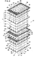
- Figure 2 is a perspecitve view of a fuel cell stack of Figure 1;
- Figure 3 is a perspecitve view of a second reformer assembly of Figure 1;
- Figure 4 is a perspective view depicting a plate type heat exchanger of Figure 1;
- Figure 5 is a fragmentary, enlarged view of a cell element of Figure 1;
- Figure 6 is a fragmentary, enlarged view of a first reforming plate of of Figure 1;
- Figure 7 shows various passages formed within the fuel cell stack;
- Figure 8 is a perspective view of a fuel cell type power generation system according to the present invention.
- Referring now to Figure 1 of the accompanying drawings, a basic construction of a fuel cell type power generation system of the present invention will be explained.
Reference numeral 10 designates a fuel cell stack which includes a plurality ofcell elements 11 andseparator plates 12. Thecell elements 11 and theseparator plates 12 are piled up one after the other. Ananode gas passage 13 and acathode gas passage 14 are respectively formed on the upper and the lower faces of theseparator plate 12. A first reformingplate 15, which is the first reformer, is provided between arbitraryadjacent separator plates 12 instead of thecell element 11.Reference numeral 16 denotes a second reformer assembly. Each second reformer includessecond reforming chambers combustion chambers dispersion chamber 19, which chambers are respectively defined withinplates heating chamber 40 and apreheating chamber 34. Theheat exchanger 23, thesecond reformer assembly 16 and thecell stack 10 are piled as one unit, and all the gas passages are formed through the unit. Numeral 24 designates another heat exchanger, 25 a desulfurizer, 26 a compressor, 27 a boiler, 28 a water softner, 29 a header, 30 and 31 ejectors, and 32 an inverter. - Raw material gas such as town gas or natural gas is desulfurized by the
desulfurizer 25, and then fed into thepreheating chamber 34 of the platetype heat exchanger 23 by theejector 30 through anexternal line 33. Water (H₂O), on the other hand, is softened by thewater softener 28 and heated to steam, and then fed also to thepreheating chamber 34 of the platetype heat exchanger 23 by theejector 30 through theexternal line 36. The raw material gas so preheated proceeds via anexternal line 37 to the first reforming chamber of the first reformingplate 15 in thecell stack 10, where it is reformed to the anode gas approximately 80%. After that, the gas proceeds to the second reformingchamber 17 of the second reformingplate 20 of thesecond reformer 16 via anexternal line 38, in which reforming chamber the residual hydrocarbon is reformed to the anode gas. The anode gas so produced flows to theheating chamber 40 of the platetype heat exchanger 23 via anexteranl line 39, thereby preheating the raw material gas passing through thepreheating chamber 34, and the same further flows into theanode gas passages 13 of thecell stack 10 via anexternal line 41. - Air, after compressed by the
compressor 26, is sent via anexternal line 42 to thepreheating chamber 43 of theheat exchanger 24 where it is preheated. Then, the air is supplied to thecombustion chamber 18 of thecombustion plates 21 of thesecond reformer assembly 16 via anexteranl line 56. Meantime, the gases flowing through theanode gas passage 13 which include the unreacted hydrogen proceed to thedispersion chamber 19 of the dispersion plate 22 and in turn thecombustion chambers combustion chamber 18, the gases including the unreacted hydrogen are burned with the air supplied thereto, and the temperature of the second reformingchamber 17 is maintained due to the combustion heat. The gas discharged from thecombustion chamber 18 is sent to theejector 31 through anexternal line 46, in which ejector it is mixed with the air coming from theheader 29 via theexternal line 35. After that, the mixutre of the discharged gas and air is fed to thecathode gas passages 14 via anexternal line 47, and in turn to theheating chamber 50 of turn to theheating cahmber 50 of theheat exchanger 24 via anexternal line 49 and to theboiler 27 thereby heating the water supplied from thesoftner 28 before being expelled through anexteranl line 51. - In the
cell stack 10, meanwhile, the gases are respectively fed to the anode gas and cathode gas passages which sandwich eachcell element 11, and power generation takes place. Electricity generated in the cell stack is picked up from the outermost anode and cathode plates and changed to the alternating current through theinvertor 32. - Referring now to Figures 2 to 4, the details of the
cell stack 10, thereformer assembly 16 and the platetype heat exchanger 23 will be explained. - Figure 2 illustrates a part of the
cell stack 10. Thecell element 11 comprises: anelectrolyte tile 60 which includes a porous ceramic plate filled with electrolyte; ananode electrode 61 and acathode electrode 62 which sandwich the tile; perforatedplates masking plates cell elements 11 and theseparator plates 12 are piled up alternately, with the first reformingplate 15 being sandwiched byarbitrary separator plates cell element 11, thereby forming thecell stack 10.Openings cell element 11, theseparator plate 12 and the first reformingplate 15, so that the external lines orpassages plate 15 are piled. - The
separator plate 12, as shown in Figure 5, is shaped like a corrugated plate so that it defines theanode gas passage 13 on one face thereof and the cathode gas passage on the other face thereof as it is sandwiched by the cell elements. - The first reforming
plate 15, as fragmentarily illustrated in Figure 6, possesses a reformingchamber 68 of cylindrical shape which extends between theopening 65 of thepassage 37 and theopening 65 of the passage 38 (not shown in Figure 6). Reformingcatalyst 70 is provided in the reformingchamber 68 and plugs 69 close both ends of the reformingchamber 68. - Referring now to Figure 3, which depicts one second reformer of the
assembly 16 sandwiched by twoend holders 85, each second reformer comprises thedispersion plate 80, perforatedplates 81 which sandwich the dispersion plate,combustion plates 82 which sandwich theperforated plates 81,heat exchanger plates 83 which sandwich the combustion plates, and second reformingplates 84 which sandwich the heat exchanger plates. Thecombustion plate 82 contains combustion catalyst. The second reformingplate 84 contains reforming catalyst. Thedispersion plates 80 possesses thedispersion chamber 19 therein, thecombustion plate 82 possesses thecombustion chamber 18 therein, and the second reformingplate 84 possesses the second reformingchamber 17 therein. Theplates bores cell stack 10 is provided. These bores define thepassages chambers - The plate
type heat exchanger 23, as depicted in Figure 4, comprises a plurality of alternately stacked fin-plates 90 and maskingplates 91 with separatingplates 92 being provided on the top and the bottom of the stack of the fin-plates and the masking plates. The platetype heat exchanger 23 is also provided with thebores passages - As perspectively illustrated in Figure 8, the plate
type heat exchanger 23, thesecond reformer assembly 16 and thecell stack 10 are piled withholders passages second reformer assembly 16 and thecell stack 10 are connected to each other via theholders passages chambers passages openings 65 bored along the short periphery of, for example, the separator plate while thepassages round openings 66 bored along the long periphery and thepassages oval openings 67 also bored along the long periphery. Thelower holder 100 has aport 71 for connecting theline 33 and thepassage 52 of the platetype heat exchanger 23, aport 72 for connecting thepassage 55 and thepassage 41, and aport 73 for connecting thepassages passage 37. The lower holder also closes thelowermost end 39a of thepassage 39. - The
holder 101 between the platetype heat exchanger 23 and thesecond reformer assembly 16 hasports heat exchange 23 and thepassages second reformer assembly 16, and closes the upper ends 52b, 53b, 54b and 55b of thepassages passages - The
holder 102 between thesecond reformer assembly 16 and thecell stack 10 hasports passages second reformer assembly 16 and the same numbered passages of thecell stack 10, aport 97 for connecting theexternal line 44 from the preheatingchamber 43 of theheat exchanger 24 and thepassage 56 of thereformer assembly 16, a port 98 for connecting thepassage 45 of thecell stack 10 and theexternal line 86 to theheating chamber 50 of theheat exchanger 24, aport 87 for connecting theejector 31 and thepassage 47 of thecell stack 10 and aport 88 for connecting thepassage 45 of thesecond reformer 16 and theejector 31. Theholder 102 also closes theupper end 39b of thepassage 39 of thereformer 16. - The
upper holder 103 closes the upper ends 37b, 38b, 41b, 45b, 47b and 49b of thepassages cell stack 10. - As appreciated from the above description, the number of the conduits or pipes which are attached from outside can be reduced since the most passages are formed within the fuel cell stack and the periphery members thereof, and those passage are connected to each other or closed by the
holders reference numeral 10 designates the cell stack, 16 the second reformer assembly, 23 the plate type heat exchanger, all of which are piled up with theholders upper presser plate 110 and associated bolts and nuts 112.Numeral 27 desingates the boiler, 24 the heat exchanger, 25 the desulfurizer, 26 the compressor, 28 the water softner, 29 the header, 30 and 31 the ejectors, 32 the inverter, 113 a water tank, 114 a water pump, 115 an auxiliary combustor, 116 a controller, and 117 a housing for the power generation system. - As appreciated from the above description, since the first reforming plate is disposed between the separator plates, the reforming temperature is maintained by the heat of the cell stack. Also, the external pipe arrangement can be simplified since the second reformer assembly and the cell stack are stacked via the holders, and the gas passages are formed in the cell stack, the reformer assembly and the holders.
- It is recongized, of course, that those skilled in the art may make various modifications or additions to the foregoing embodiment chosed to illustrate the invention without departing from the spirit and scope of the present contribution to the art. For example, the cathode gas may flow in counter directions in the
adjacent passages type heat exchanger 23 may not be necessarily disposed under thesecond reformer assembly 16.
Claims (28)
a cell stack (10) including alternately piled up fuel cell elements (11) and separator plates (12), each fuel cell element (11) having an anode electrode (61), an electrolyte (60) and a cathode electrode (62); and
reforming devices (15, 16) for reforming fuel gas to anode gas,
characterized in that said reforming devices include :
a first reformer (15) for partially reforming fuel gas to anode gas interposed between the separator plates (12) instead of the cell element (11), the first reformer including a first reforming plate (15); and
a second reformer assembly (16) for reforming the remainder of the fuel gas to the anode gas, the second reformer assembly (16) including a plurality of plate type second reformers (16), and each second reformer including plate type members (80, 82, 84); and
said power generation system further includes:
an intermediate holder (102) interposed between the cell stack (10) and the second reformer assembly (16) as they are piled up;
an upper and a lower holders (103, 100) for sandwiching the cell stack (10), the intermediate holder (102) and the second reformer assembly (16) so as to make them one unit; and
gas passages (37, 38, 47 to 49)formed within the cell stack (10), the second reformer assembly (16), and the intermediate, the upper and the lower holders (102, 103, 100).
a cell stack (10) including alternately piled up fuel cell elements (11) and separator plates (12), each fuel cell element (11) having an anode electrode (61), an electrolyte (60) and a cathode electrode (62); and
reforming devices (15, 16) for reforming fuel gas to anode gas,
characterized in that said reforming devices includes:
a first reformer (15) for partially reforming fuel gas to anode gas interposed between the separator plates (12) instead of the cell element (11), the first reformer (15) including a first reforming plate (15); and
a second reformer assembly (16) for reforming the remainder of the fuel gas to the anode gas, the second reformer assembly (16) including a plurality of plate type second reformers (16) and each second reformer including a plurality of plate type members (20, 21, 22); and
said power generation system further includes:
a plate type heat exchanger (23) which includes:
a preheating chamber (34) in which the fuel gas and the steam are introduced, and
a heating chamber (40) in which the anode gas is introduced;
a first intermediate holder (102) interposed between the cell stack (10) and the second reformer assembly (16) as they are piled up;
a second intermediate holder (101) interposed between the second reformer assembly (16) and the plate type heat exchanger (23) as they are piled up;
an upper and a lower holders (103)(100) for sandwiching the cell stack (10), the first and second intermediate holders (102, 101), the second reformer assembly (16) and the plate type heat exchanger (23), so as to make them one unit; and
gas passages (93, 94, 95, 96, 97, 73, 72, 74, 75) formed within the cell stack (10), the second reformer assembly (16), the plate type heat exchanger (23), and the first intermediate, the second intermediate, the upper and the lower holders (100, 101, 102, 103).
each second reformer (16) including;
a dispersion plate (22) which has a dispersion chamber (19);
combustion plates (21) which sandwich the dispersion plate (22), each combustion plate (21) having a combustion chamber (18); and
second reforming plates (20) which sandwich the combustion plates (21), each second reforming plate (20) having a second reforming chamber (17).
passages (37, 38) for supplying/discharging the fuel gas to/from the first reforming plate (15);
passages (41, 45) for supplying/discharging and anode gas to/from the anode gas passages(13); and
passages (47, 49) for supplying/discharging the cathode gas to/from the cathode gas passages (14),
all the passages (37, 38, 41, 45, 47, 49) being defined by openings (65, 66, 67)formed in the cell elements (11), the separator plates (12), and the first reforming plate (15) along the periphery thereof as they are stacked and aligned.
passages (38, 39) for supplying/discharging the gas reformed by the first reforming plate (15) to/from the second reforming plates (18);
passages (56, 46) for supplying/discharging the combustion air to/from the combustion chambers (18); and
passage (45) for supplying/discharging the fuel gas to/from the dispersion chambers (19),
all the passages (38, 39, 46, 45) being defined by openings (65, 66, 67) formed in the second reforming plates (20), the combustion plates (21) and the dispersion plate (22) along the periphery thereof as they are stacked and aligned.
passages (52, 53, 54) for supplying/discharging the fuel gas and the steam to/from the preheating chambers (34);
passages (39, 55, 41) for supplying/discharging the anode gas to/from the heating chambers (40);
all the passages (39, 41, 52, 53, 54, 55) being defined by openings (65, 66, 67) formed in the fin-plates (90) along the periphery thereof as they are piled up and aligned.
Applications Claiming Priority (2)
| Application Number | Priority Date | Filing Date | Title |
|---|---|---|---|
| JP1045449A JPH07109773B2 (en) | 1989-02-28 | 1989-02-28 | Power generator using fuel cell |
| JP45449/89 | 1989-02-28 |
Publications (2)
| Publication Number | Publication Date |
|---|---|
| EP0384944A1 true EP0384944A1 (en) | 1990-09-05 |
| EP0384944B1 EP0384944B1 (en) | 1993-02-03 |
Family
ID=12719651
Family Applications (1)
| Application Number | Title | Priority Date | Filing Date |
|---|---|---|---|
| EP89109529A Expired - Lifetime EP0384944B1 (en) | 1989-02-28 | 1989-05-26 | Power generation system with use of fuel cell |
Country Status (4)
| Country | Link |
|---|---|
| US (1) | US4933242A (en) |
| EP (1) | EP0384944B1 (en) |
| JP (1) | JPH07109773B2 (en) |
| DE (1) | DE68904763T2 (en) |
Cited By (9)
| Publication number | Priority date | Publication date | Assignee | Title |
|---|---|---|---|---|
| EP0429958A3 (en) * | 1989-11-25 | 1991-07-24 | Ishikawajima-Harima Heavy Industries Co., Ltd. | Power generation system using molten carbonate fuel cell |
| WO1991011034A1 (en) * | 1990-01-10 | 1991-07-25 | International Fuel Cells Corporation | Molten carbonate fuel cell power plant |
| EP0459940A1 (en) * | 1990-05-01 | 1991-12-04 | Institute of Gas Technology | Fully internal manifolded and internal reforming fuel stack |
| US5227256A (en) * | 1989-05-03 | 1993-07-13 | Institute Of Gas Technology | Fully internal manifolded fuel cell stack |
| US5342706A (en) * | 1989-05-03 | 1994-08-30 | Institute Of Gas Technology | Fully internal manifolded fuel cell stack |
| EP0805328A3 (en) * | 1996-05-02 | 1999-03-10 | Ballard Power Systems Inc. | Flow module |
| WO2004082057A1 (en) * | 2003-03-12 | 2004-09-23 | Forschungszentrum Jülich GmbH | Modularly built high-temperature fuel cell system |
| EP1471994A4 (en) * | 2002-01-04 | 2009-03-18 | Meggitt Uk Ltd | Chemical reactor |
| EP2040325A4 (en) * | 2006-07-05 | 2011-11-09 | Nippon Oil Corp | INDIRECT INTERNAL REFORMATION SOLID OXIDE FUEL CELL SYSTEM |
Families Citing this family (60)
| Publication number | Priority date | Publication date | Assignee | Title |
|---|---|---|---|---|
| DK162245C (en) * | 1989-06-19 | 1992-02-17 | Haldor Topsoe As | FUEL CELL SYSTEM |
| US5314180A (en) * | 1989-08-28 | 1994-05-24 | Toray Industries, Inc. | Sports instrument and impact-absorbing element to be attached to sports equipment |
| JPH03109126A (en) * | 1989-09-21 | 1991-05-09 | Yamaha Motor Co Ltd | Electric automobile using fuel battery |
| US5221586A (en) * | 1990-09-19 | 1993-06-22 | Ishikawajima-Harima Heavy Industries Co., Ltd. | Power generation system using fuel cells |
| US5209906A (en) * | 1991-05-10 | 1993-05-11 | Her Majesty The Queen In Right Of Canada, As Represented By The Minister Of National Defence | Modular isothermal reactor |
| JPH0541241A (en) * | 1991-05-30 | 1993-02-19 | Fuji Electric Co Ltd | Solid electrolyte type fuel cell |
| US5270127A (en) * | 1991-08-09 | 1993-12-14 | Ishikawajima-Harima Heavy Industries Co., Ltd. | Plate shift converter |
| US5316747A (en) * | 1992-10-09 | 1994-05-31 | Ballard Power Systems Inc. | Method and apparatus for the selective oxidation of carbon monoxide in a hydrogen-containing gas mixture |
| GB9403198D0 (en) * | 1994-02-19 | 1994-04-13 | Rolls Royce Plc | A solid oxide fuel cell stack |
| GB9403234D0 (en) * | 1994-02-19 | 1994-04-13 | Rolls Royce Plc | A solid oxide fuel cell stack and a reactant distribution member therefor |
| JPH0812303A (en) * | 1994-07-05 | 1996-01-16 | Ishikawajima Harima Heavy Ind Co Ltd | Plate reformer |
| AU700865B2 (en) * | 1994-07-05 | 1999-01-14 | Ishikawajima-Harima Heavy Industries Co., Ltd. | Molten carbonate power generation system |
| US5658537A (en) * | 1995-07-18 | 1997-08-19 | Basf Corporation | Plate-type chemical reactor |
| US5733675A (en) * | 1995-08-23 | 1998-03-31 | Westinghouse Electric Corporation | Electrochemical fuel cell generator having an internal and leak tight hydrocarbon fuel reformer |
| DE10001064B4 (en) * | 2000-01-13 | 2004-03-11 | Ballard Power Systems Ag | Reforming reactor in layered construction |
| DE10033594B4 (en) * | 2000-07-11 | 2006-07-06 | Nucellsys Gmbh | Fuel cell and use thereof in a motor vehicle |
| EP1372839A4 (en) * | 2001-03-02 | 2006-11-29 | Mesofuel Inc | Ammonia-based hydrogen generation apparatus and method for using same |
| US7922781B2 (en) | 2001-03-02 | 2011-04-12 | Chellappa Anand S | Hydrogen generation apparatus and method for using same |
| US7867300B2 (en) * | 2001-03-02 | 2011-01-11 | Intelligent Energy, Inc. | Ammonia-based hydrogen generation apparatus and method for using same |
| US20020168307A1 (en) | 2001-03-09 | 2002-11-14 | James Seaba | Micro component hydrocarbon steam reformer system and cycle for producing hydrogen gas |
| WO2002085509A1 (en) * | 2001-04-24 | 2002-10-31 | Hydrogen Burner Technology, Inc. | Flat plate integrated reactor |
| CN1264600C (en) * | 2001-04-26 | 2006-07-19 | 德士古发展公司 | Compact single chamber fuel handling unit |
| US7967878B2 (en) * | 2002-01-04 | 2011-06-28 | Meggitt (Uk) Limited | Reformer apparatus and method |
| US7527661B2 (en) * | 2005-04-18 | 2009-05-05 | Intelligent Energy, Inc. | Compact devices for generating pure hydrogen |
| US8172913B2 (en) * | 2002-04-23 | 2012-05-08 | Vencill Thomas R | Array of planar membrane modules for producing hydrogen |
| US7261960B2 (en) * | 2003-05-16 | 2007-08-28 | General Motors Corporation | Apparatus and method for internal stack temperature control |
| EP1600374B1 (en) * | 2004-05-28 | 2008-09-17 | Airbus Deutschland GmbH | Electrochemical reactor for aircraft and method for its operation |
| US7524575B2 (en) * | 2004-06-07 | 2009-04-28 | Hyteon Inc. | Flow field plate for use in fuel cells |
| US7531264B2 (en) * | 2004-06-07 | 2009-05-12 | Hyteon Inc. | Fuel cell stack with even distributing gas manifolds |
| DE102004033545B4 (en) * | 2004-07-09 | 2006-06-14 | J. Eberspächer GmbH & Co. KG | burner |
| US20060008695A1 (en) * | 2004-07-09 | 2006-01-12 | Dingrong Bai | Fuel cell with in-cell humidification |
| US7687183B2 (en) * | 2004-08-25 | 2010-03-30 | Gm Global Technology Operations, Inc. | Electrochemical fuel cell elements having improved compression over channels |
| US7314680B2 (en) * | 2004-09-24 | 2008-01-01 | Hyteon Inc | Integrated fuel cell power module |
| US7479333B2 (en) * | 2004-12-13 | 2009-01-20 | Hyteon, Inc. | Fuel cell stack with multiple groups of cells and flow passes |
| US20060188763A1 (en) * | 2005-02-22 | 2006-08-24 | Dingrong Bai | Fuel cell system comprising modular design features |
| KR101155910B1 (en) * | 2005-03-16 | 2012-06-20 | 삼성에스디아이 주식회사 | Stack capable of reforming action and fuel cell system with the same |
| WO2007087305A2 (en) * | 2006-01-23 | 2007-08-02 | Bloom Energy Corporation | Integrated solid oxide fuel cell and fuel processor |
| WO2007087240A2 (en) | 2006-01-23 | 2007-08-02 | Bloom Energy Corporation | Modular fuel cell system |
| US7659022B2 (en) * | 2006-08-14 | 2010-02-09 | Modine Manufacturing Company | Integrated solid oxide fuel cell and fuel processor |
| KR100731329B1 (en) * | 2006-02-10 | 2007-06-21 | 두산중공업 주식회사 | Separation plate for molten carbonate fuel cell including fuel reforming chamber and manufacturing method thereof |
| DE102006037353A1 (en) * | 2006-08-09 | 2008-02-14 | Behr Gmbh & Co. Kg | Device for carrying out a chemical reaction |
| US8241801B2 (en) | 2006-08-14 | 2012-08-14 | Modine Manufacturing Company | Integrated solid oxide fuel cell and fuel processor |
| US8920997B2 (en) | 2007-07-26 | 2014-12-30 | Bloom Energy Corporation | Hybrid fuel heat exchanger—pre-reformer in SOFC systems |
| US8852820B2 (en) | 2007-08-15 | 2014-10-07 | Bloom Energy Corporation | Fuel cell stack module shell with integrated heat exchanger |
| JP5307376B2 (en) * | 2007-10-04 | 2013-10-02 | 日本特殊陶業株式会社 | Fuel reforming fuel cell |
| US8288041B2 (en) | 2008-02-19 | 2012-10-16 | Bloom Energy Corporation | Fuel cell system containing anode tail gas oxidizer and hybrid heat exchanger/reformer |
| US8968958B2 (en) * | 2008-07-08 | 2015-03-03 | Bloom Energy Corporation | Voltage lead jumper connected fuel cell columns |
| IT1394740B1 (en) * | 2009-07-14 | 2012-07-13 | Ansaldo Fuel Cells Spa | APPARATUS AND METHOD FOR THERMAL MANAGEMENT OF MCFC PILE |
| DE102009050214A1 (en) * | 2009-10-22 | 2011-07-28 | BAXI INNOTECH GmbH, 20539 | Device for guiding at least one fluid and fuel cell heater |
| US8440362B2 (en) | 2010-09-24 | 2013-05-14 | Bloom Energy Corporation | Fuel cell mechanical components |
| US8968943B2 (en) | 2011-01-06 | 2015-03-03 | Bloom Energy Corporation | SOFC hot box components |
| JP5961941B2 (en) * | 2011-07-27 | 2016-08-03 | 株式会社Ihi | Sealed gas heater and continuous heating furnace using sealed gas heater |
| US9755263B2 (en) | 2013-03-15 | 2017-09-05 | Bloom Energy Corporation | Fuel cell mechanical components |
| WO2015061274A1 (en) | 2013-10-23 | 2015-04-30 | Bloom Energy Corporation | Pre-reformer for selective reformation of higher hydrocarbons |
| JP6566425B2 (en) | 2014-02-12 | 2019-08-28 | ブルーム エネルギー コーポレイション | STRUCTURE AND METHOD FOR FUEL CELL SYSTEM WITH MULTIPLE FUEL CELLS AND POWER ELECTRONICS POWERING A LOAD IN PARALLEL CONSIDERING INTEGRATED ELECTROCHEMICAL IMPEDANCE SPECTROSCOPY |
| US20150357664A1 (en) * | 2014-06-05 | 2015-12-10 | Szu-Han Wu | Plate type fuel reformer of fuel cell |
| JP5828468B1 (en) * | 2014-12-26 | 2015-12-09 | マグネクス株式会社 | Solid oxide fuel cell system |
| US10651496B2 (en) | 2015-03-06 | 2020-05-12 | Bloom Energy Corporation | Modular pad for a fuel cell system |
| US11398634B2 (en) | 2018-03-27 | 2022-07-26 | Bloom Energy Corporation | Solid oxide fuel cell system and method of operating the same using peak shaving gas |
| TW202315201A (en) | 2021-06-25 | 2023-04-01 | 美商博隆能源股份有限公司 | Handling of variable and unpredictable gas composition changes to maximize health and performance of fuel cell systems |
Citations (4)
| Publication number | Priority date | Publication date | Assignee | Title |
|---|---|---|---|---|
| US3488226A (en) * | 1965-11-08 | 1970-01-06 | Inst Gas Technology | Process for generation of hydrogen from hydrocarbons and use thereof in molten carbonate fuel cells |
| US4647516A (en) * | 1985-02-20 | 1987-03-03 | Mitsubishi Denki Kabushiki Kaisha | Internal reforming type fuel cell |
| EP0230036A1 (en) * | 1985-12-23 | 1987-07-29 | Energy Research Corporation | Fuel cell apparatus with internal reforming |
| US4753857A (en) * | 1984-05-29 | 1988-06-28 | Ishikawajima-Harima Jukogyo Kabushiki Kaisha | Laminated fuel cell |
Family Cites Families (2)
| Publication number | Priority date | Publication date | Assignee | Title |
|---|---|---|---|---|
| US3881956A (en) * | 1972-07-28 | 1975-05-06 | Gen Engineering Lab Inc | Fuel cell construction |
| JPH0797503B2 (en) * | 1987-03-19 | 1995-10-18 | 工業技術院長 | Molten carbonate fuel cell power generator |
-
1989
- 1989-02-28 JP JP1045449A patent/JPH07109773B2/en not_active Expired - Lifetime
- 1989-05-15 US US07/362,612 patent/US4933242A/en not_active Expired - Fee Related
- 1989-05-26 DE DE8989109529T patent/DE68904763T2/en not_active Expired - Fee Related
- 1989-05-26 EP EP89109529A patent/EP0384944B1/en not_active Expired - Lifetime
Patent Citations (4)
| Publication number | Priority date | Publication date | Assignee | Title |
|---|---|---|---|---|
| US3488226A (en) * | 1965-11-08 | 1970-01-06 | Inst Gas Technology | Process for generation of hydrogen from hydrocarbons and use thereof in molten carbonate fuel cells |
| US4753857A (en) * | 1984-05-29 | 1988-06-28 | Ishikawajima-Harima Jukogyo Kabushiki Kaisha | Laminated fuel cell |
| US4647516A (en) * | 1985-02-20 | 1987-03-03 | Mitsubishi Denki Kabushiki Kaisha | Internal reforming type fuel cell |
| EP0230036A1 (en) * | 1985-12-23 | 1987-07-29 | Energy Research Corporation | Fuel cell apparatus with internal reforming |
Non-Patent Citations (5)
| Title |
|---|
| PATENT ABSTRACTS OF JAPAN, vol. 11, no. 306 (E-546)[2753], 6th October 1987; & JP-A-62 098 567 (HITACHI LITD) 08-05-1987 * |
| PATENT ABSTRACTS OF JAPAN, vol. 12, no. 200 (E-619)[3047], 9th June 1988; & JP-A-63 000 976 (HITACHI LTD) 05-01-1988 * |
| PATENT ABSTRACTS OF JAPAN, vol. 12, no. 273 (E-639)[3120], 29th July 1988; & JP-A-63 053 858 (ISHIKAWAJIMA HARIMA HEAVY IND. CO. LTD) 08-03-1988 * |
| PATENT ABSTRACTS OF JAPAN, vol. 13, no. 474 (E-836)[3822], 26th October 1989; & JP-A-01 186 565 (ISHIKAWAJIMA HARIMA HEAVY IND. CO. LTD) 26-07-1989 * |
| PATENT ABSTRACTS OF JAPAN, vol. 13, no. 571 (E-862)[3919], 18th December 1989; & JP-A-01 239 773 (ISHIKAWAJIMA HARIMA HEAVY IND. CO. LTD) 25-09-1989 * |
Cited By (12)
| Publication number | Priority date | Publication date | Assignee | Title |
|---|---|---|---|---|
| US5227256A (en) * | 1989-05-03 | 1993-07-13 | Institute Of Gas Technology | Fully internal manifolded fuel cell stack |
| US5342706A (en) * | 1989-05-03 | 1994-08-30 | Institute Of Gas Technology | Fully internal manifolded fuel cell stack |
| EP0429958A3 (en) * | 1989-11-25 | 1991-07-24 | Ishikawajima-Harima Heavy Industries Co., Ltd. | Power generation system using molten carbonate fuel cell |
| WO1991011034A1 (en) * | 1990-01-10 | 1991-07-25 | International Fuel Cells Corporation | Molten carbonate fuel cell power plant |
| US5084363A (en) * | 1990-01-10 | 1992-01-28 | International Fuel Cells Corp. | Molten carbonate fuel cell power plant |
| EP0459940A1 (en) * | 1990-05-01 | 1991-12-04 | Institute of Gas Technology | Fully internal manifolded and internal reforming fuel stack |
| EP0805328A3 (en) * | 1996-05-02 | 1999-03-10 | Ballard Power Systems Inc. | Flow module |
| EP1471994A4 (en) * | 2002-01-04 | 2009-03-18 | Meggitt Uk Ltd | Chemical reactor |
| NO338329B1 (en) * | 2002-01-04 | 2016-08-08 | Meggitt Uk Ltd | Chemical reactor |
| WO2004082057A1 (en) * | 2003-03-12 | 2004-09-23 | Forschungszentrum Jülich GmbH | Modularly built high-temperature fuel cell system |
| EP2040325A4 (en) * | 2006-07-05 | 2011-11-09 | Nippon Oil Corp | INDIRECT INTERNAL REFORMATION SOLID OXIDE FUEL CELL SYSTEM |
| US8841039B2 (en) | 2006-07-05 | 2014-09-23 | Nippon Oil Corporation | Indirect internal reforming solid oxide fuel cell system |
Also Published As
| Publication number | Publication date |
|---|---|
| DE68904763T2 (en) | 1993-08-19 |
| US4933242A (en) | 1990-06-12 |
| JPH02226667A (en) | 1990-09-10 |
| DE68904763D1 (en) | 1993-03-18 |
| JPH07109773B2 (en) | 1995-11-22 |
| EP0384944B1 (en) | 1993-02-03 |
Similar Documents
| Publication | Publication Date | Title |
|---|---|---|
| EP0384944B1 (en) | Power generation system with use of fuel cell | |
| JP3930045B2 (en) | Fuel cell module having a multi-fuel cell stack | |
| US5077148A (en) | Fully internal manifolded and internal reformed fuel cell stack | |
| JP3516693B2 (en) | Fuel cell stack with complete internal manifold | |
| EP0369059B1 (en) | Method of ameliorating temperature distribution of a fuel cell | |
| KR102015482B1 (en) | Internally reforming fuel cell assembly with staged fuel flow and selective catalyst loading for improved temperature uniformity and efficiency | |
| CN102870264B (en) | Thermal Management in Fuel Cell Stacks | |
| US8309263B2 (en) | Fuel cell assembly and electricity generation unit used in same | |
| JPH03105865A (en) | Inside reformed type fuel cell and power plant using it | |
| KR20040050872A (en) | Methods and apparatus for assembling solid oxide fuel cells | |
| JP2017050192A (en) | Fuel cell module | |
| EP1712274A1 (en) | Reformer for a Fuel Cell System | |
| CN100369310C (en) | Fuel cell system and its reformer | |
| WO2011015261A1 (en) | Solid oxide fuel cell system | |
| CN113241462A (en) | Combined type molten carbonate fuel cell power generation system and method | |
| JPH08102326A (en) | Fuel cell power generating system | |
| US6602626B1 (en) | Fuel cell with internal thermally integrated autothermal reformer | |
| KR101198629B1 (en) | Stack and molten carbonate fuel cell having the same | |
| JPS6160548B2 (en) | ||
| CN1835270B (en) | Battery stack with reforming function and fuel cell system with the same | |
| JP5228342B2 (en) | Fuel reformer and fuel cell | |
| JPH0644993A (en) | Solid oxide fuel cell | |
| JPS6160547B2 (en) | ||
| US20050130020A1 (en) | Fuel cell | |
| CA1308776C (en) | Fuel cell and method of ameliorating temperature distribution thereof |
Legal Events
| Date | Code | Title | Description |
|---|---|---|---|
| PUAI | Public reference made under article 153(3) epc to a published international application that has entered the european phase |
Free format text: ORIGINAL CODE: 0009012 |
|
| AK | Designated contracting states |
Kind code of ref document: A1 Designated state(s): AT BE CH DE ES FR GB GR IT LI LU NL SE |
|
| RBV | Designated contracting states (corrected) |
Designated state(s): DE GB IT NL |
|
| 17P | Request for examination filed |
Effective date: 19901116 |
|
| 17Q | First examination report despatched |
Effective date: 19911031 |
|
| GRAA | (expected) grant |
Free format text: ORIGINAL CODE: 0009210 |
|
| AK | Designated contracting states |
Kind code of ref document: B1 Designated state(s): DE GB IT NL |
|
| REF | Corresponds to: |
Ref document number: 68904763 Country of ref document: DE Date of ref document: 19930318 |
|
| ITF | It: translation for a ep patent filed | ||
| PGFP | Annual fee paid to national office [announced via postgrant information from national office to epo] |
Ref country code: GB Payment date: 19930513 Year of fee payment: 5 |
|
| PGFP | Annual fee paid to national office [announced via postgrant information from national office to epo] |
Ref country code: DE Payment date: 19930514 Year of fee payment: 5 |
|
| PLBE | No opposition filed within time limit |
Free format text: ORIGINAL CODE: 0009261 |
|
| STAA | Information on the status of an ep patent application or granted ep patent |
Free format text: STATUS: NO OPPOSITION FILED WITHIN TIME LIMIT |
|
| 26N | No opposition filed | ||
| PG25 | Lapsed in a contracting state [announced via postgrant information from national office to epo] |
Ref country code: GB Effective date: 19940526 |
|
| GBPC | Gb: european patent ceased through non-payment of renewal fee |
Effective date: 19940526 |
|
| PG25 | Lapsed in a contracting state [announced via postgrant information from national office to epo] |
Ref country code: DE Effective date: 19950201 |
|
| PGFP | Annual fee paid to national office [announced via postgrant information from national office to epo] |
Ref country code: NL Payment date: 19970531 Year of fee payment: 9 |
|
| PG25 | Lapsed in a contracting state [announced via postgrant information from national office to epo] |
Ref country code: NL Free format text: LAPSE BECAUSE OF NON-PAYMENT OF DUE FEES Effective date: 19981201 |
|
| NLV4 | Nl: lapsed or anulled due to non-payment of the annual fee |
Effective date: 19981201 |
|
| PG25 | Lapsed in a contracting state [announced via postgrant information from national office to epo] |
Ref country code: IT Free format text: LAPSE BECAUSE OF NON-PAYMENT OF DUE FEES Effective date: 20050526 |