EP0385768A2 - Automatisches Filmentwicklungsgerät - Google Patents
Automatisches Filmentwicklungsgerät Download PDFInfo
- Publication number
- EP0385768A2 EP0385768A2 EP90302169A EP90302169A EP0385768A2 EP 0385768 A2 EP0385768 A2 EP 0385768A2 EP 90302169 A EP90302169 A EP 90302169A EP 90302169 A EP90302169 A EP 90302169A EP 0385768 A2 EP0385768 A2 EP 0385768A2
- Authority
- EP
- European Patent Office
- Prior art keywords
- reservoir
- film
- housing
- chemical
- chemical solutions
- Prior art date
- Legal status (The legal status is an assumption and is not a legal conclusion. Google has not performed a legal analysis and makes no representation as to the accuracy of the status listed.)
- Granted
Links
Images


Classifications
-
- G—PHYSICS
- G03—PHOTOGRAPHY; CINEMATOGRAPHY; ANALOGOUS TECHNIQUES USING WAVES OTHER THAN OPTICAL WAVES; ELECTROGRAPHY; HOLOGRAPHY
- G03D—APPARATUS FOR PROCESSING EXPOSED PHOTOGRAPHIC MATERIALS; ACCESSORIES THEREFOR
- G03D13/00—Processing apparatus or accessories therefor, not covered by groups G11B3/00 - G11B11/00
- G03D13/02—Containers; Holding-devices
- G03D13/04—Trays; Dishes; Tanks ; Drums
- G03D13/046—Drums; Films convolutely fixed on the side of the drum
Definitions
- the present invention relates to film processing machines and more particularly, to an automatic film processing machine that can supply a plurality of chemicals for different processes to the film to be developed and carefully purges the last used chemical from the system prior to supplying the next needed chemical.
- the art abounds with automatic film processing machines suitable for handling developing of particular types of roll or disk films.
- the developing process requires chemical solutions, the pre-heating of these solutions and applying the chemical solutions to the film to be developed in a light tight environment.
- the process is enormously time consuming, requiring critical temperature maintenance, and also requires that prior to applying a new chemical solution to the system, the old chemical solution must be completely purged. All of these steps must be performed carefully.
- an automatic film processor characterised in that the processor comprises a light tight container for storing undeveloped film and including a coupling connector port for the ingress and egress of chemical solutions, mounting means for mounting the film in the container, an agitating coupling means coupled to the mounting means for producing movement thereof, the container providing a first reservoir for receiving selected chemicals in liquid form for use in developing the film, and a controlling device for controlling a series of steps of ingress and egress of chemicals for developing the film.
- All existing machines require extended warm up times prior to beginning a process.
- the instant invention quickly heats only the small amount of solution needed for a particular step of the process.
- Known apparatuses require pressurized tepid water for washes.
- the instant invention treats water as just another chemical solution, heating it as required, therefore eliminating a need for tepid water.
- a pressurized water source is not needed with the instant invention since the water is pumped into the reservoirs, making it easier to set up the apparatus in the field.
- the apparatus of the instant invention has disposed therein and/or access to all the solutions needed for colour slide, colour negative and black and white films.
- the operator of the apparatus can select the process desired by activating a switch which provides for the proper chemical solution at the required temperature at the proper time with the desired agitation to obtain perfect results.
- An automatic film processor for processing roll or disk film may comprise in combination, a removable drum device for storing the undeveloped film in a light free chamber and includes a single coupling connector port which is used for the ingress and egress of chemical solutions, a mounting apparatus for mounting the film therein which is provided with an agitating coupling means disposed on the distal end of the mounting device and extends external to the drum.
- the removable drum includes a first reservoir which receives a plurality of chemical solutions to cover a portion of the removable drum.
- a housing receives the removable drum and is provided with a single mating coupling connector port also used for the ingress and egress of the chemical solutions.
- a heater and blower is disposed in the housing and provides a stream of heated air over the housing in order to maintain the film to be developed at a constant temperature.
- a driver motor disposed on the housing has a rotary output shaft which mates with the agitating coupling provided on the film mounting device and provides both rotary and longitudinal motion to the film.
- a linear valve apparatus is disposed within the housing and has a single egress port and a plurality of ingress ports, each of the ingress ports are individually selectable and coupled to the chemical solutions.
- a valve motor disposed in the housing is coupled to the linear valve and controls the selection of only one chemical solution at a time.
- a second reservoir disposed in the housing, stores one of the liquid chemicals at a time which is heated and stirred therein to a prescribed temperature and is pumped, via an additional pump into the first reservoir after the system is purged of the prior chemical solution that was used. All of the above steps are timed and controlled by a control device circuit arrangement.
- an automatic film processor for processing roll, sheet or disc film comprising, in combination: (A) removable drum means for storing said undeveloped film in a light free chamber, said drum means including; (a) a single coupling connector port means utilized for the ingress and egress of chemical solutions, (b) removable mounting means for mounting said film therein, said mounting means including, (i) an agitating coupling means disposed on one distal end and extending external to said drum means, and (c) a first reservoir, said first reservoir being adapted to receive a plurality of chemical solutions and said removable mounting means, a portion of said mounting means being submersible in said liquid chemical solutions; (B) housing means, said housing means including; (a) a single mating coupling connector port means for the ingress and egress of said chemical solutions; (b) heater and blower means for providing heated air over said drum means; (c) first drive motor means, said driver motor means being adapted to be connected to a source of electrical power and including; (i
- said removable drum means comprises said removable drum means, comprises: (a) a base member, functioning as said first reservoir, having said coupling connector port means extending longitudinally from one distal end; (b) said agitating coupling means being disposed to extend from said base member generally parallel to said outwardly extending coupling connector port means; and (c) cover means adapted to cooperate and cover said base member and maintain a light tight assembly.
- Said base member may further include a pair of generally W-shaped spring clips, one of said spring clips being affixed on each distal edge of said base member, the arms of said generally W-shaped spring clips being adapted to engage and removably retain a channeled ledge provided on said cover means.
- Said coupling connector port means may be provided with means for sealing said coupling connector port to prevent said chemical solutions from leaking therefrom.
- Said agitating coupling means may comprise: (A) a female portion including; (a) a pair of, generally, S-shaped wire members having a generally straight central portion, (b) a base member having one end of each S-shaped wire member affixed therein along a straight line, each said S-shaped wire member being disposed proximate the edge of said base members with the other end of each said wire members extending longitudinally outwardly so that they are in close proximity; and (B) said cooperating agitating coupling means comprises a male portion including; (a) a generally U-shaped wire member having a central portion and two arm portions, said central portion being adapted to cooperate with and fit between said S-shaped members, and (b) a base member, the arm portion of said U-shaped wire member being affixed in said male portion base member, wherein when said cooperating agitating coupling is coupled to said agitating coupling and rotated, said cooperating agitating coupling will couple rotary and longitudinal motion to said agitating coupling.
- Said mounting means may include a plurality of reels each adapted to receive said roll film thereon for processing.
- Said heater and blower means may further include first temperature sensing means for sensing the temperature of said heated air provided over said drum means and maintaining the temperature of said heated air at the required value.
- Said first drive motor may be capable of reversing directions.
- Said linear valve means may comprise (A) a hollow elongated housing having said plurality of ingress ports linearly disposed along the circumference of said housing, each of said ingress ports being provided with coupling means adapted to receive one end of a hose suitable for carrying said chemical solutions therethrough, the other end of each said hose being coupled to a source of said chemical solutions; (B) a hollow elongated plunger member having; (i) one end adapted to receive a hose thereon for carrying said chemical solutions therethrough, (ii) the other end being sealed and provided with a through aperature proximate thereto, (iii) a pair of O-rings disposed on said elongated member, one of said O-rings being disposed on each side of said through aperture, said O-rings and said elongated member being adapted to be slidably received into said hollow housing, said O-rings preventing said chemical solutions from flowing in a path other than through said through aperture, and (iv) at least one first
- Said valve motor means may be coupled to said rod means for providing said rotary motion.
- Said second reservoir stirring means may includes: (a) a drive motor disposed below the bottom of said second reservoir; and (b) an impeller means disposed in said second reservoir magnetically coupled to said stirring means drive motor.
- Said second reservoir means may include: (a) means for sensing the level of said chemical solution disposed within said second reservoir; and (b) sensing means coupled to said first pump means for stopping said first pump means from pumping additional amounts of chemical solution when the proper level is reached.
- An automatic film processing method utilizing the processor as set forth hereinbefore may comprise the following steps: (a) installing the film to be processed into said removable drum means; (b) placing said drum means upon said housing means so that said housing cooperating coupling means engages said drum means said agitating coupling means and said cooperating agitating coupling means, coupling means, and said removable mounting means is disposed in said first reservoir to be partially covered by a chemical solution when said first reservoir is filled to an operating level; (c) preheating said drum means and said film disposed therein to the operating temperature; (d) purging said first reservoir of any prior liquid chemical solution remaining therein; (e) evenly preheating a first chemical solution in said second reservoir; (f) pumping said heated first chemical solution into said first reservoir from said second reservoir until the operating level of the first reservoir is reached; (g) rotating and agitating said drum means for a predetermined amount of time; (h) purging a selector valve; (i) selecting a second chemical solution for preheating; (j) pumping said second chemical solution
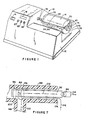
- an automatic film processor 10 which includes a housing 12 and a removable drum 14 into which may be loaded multiple rolls of film or a plurality of disks, not shown, for processing.
- the housing 12 in additional to including the necessary circuitry for automatically controlling and performing the necessary steps for the development of film includes, as one might expect, an on/off switch 16, a liquid crystal display 18 which may indicate which step in the process is being performed at the present time and the amount of time remaining in the selected step as well as indicator switches 20, 22 and 24 for selecting operating functions, film type, developing time for modifying the standard process.
- the drum 14 is removable and is more clearly shown in Figure 2 with its cover member 26 removed from the base member 28.
- Installed on the base member 28 on a removable mounting shaft 30 are a plurality of conventional film loading reels 32, 34, 36 and 38 which slide onto shaft 30 in a conventional manner and will rotate therewith.
- Disposed on one end 40 is an agitating coupling device 42, which will be explained in more detail hereinafter.
- Also provided in base member 28 is a coupling connector port 44 utilized for the ingress and egress of chemical solutions.
- the port or aperture 44 is provided in a longitudinally extending member 46 extending from one end 48 of base member 28.
- Extending member 46 is also provided with at least one O-ring 52 and may include a second O-ring 50 to insure proper seating and snug fitting within the mating coupling connector 54 (shown in Figure 4) disposed within the housing 12.
- Member 46 may be integrally molded in base member 28 or may be a hollow cylindrically-shaped member formed separately and held therein by conventional means, such as glue, epoxy, etc 58.
- glue, epoxy, etc 58 When member 46 is inserted into base member 28 a right angle fluid flow path in chamber 60 is provided in order to maintain the housing's light tight integrity so that light appearing through the coupling connector port 44 cannot reach the film placed on the reels 32, 34, 36 and 38 prior to insertion into the mating coupling 54 (see Figure 5).
- An extending thumb tab 61 is affixed between end 48 of base member 28 and extending member 46 which acts as reinforcement because of the right angle joint made therein and it also helps when an individual installs the extending member 46 into its mating coupling 54.
- edges 62 of base member 28 is provided with an upwardly extending wall 64 completely surrounding the base member and which is designed to cooperate with and receive a corresponding protruding edge or lip 66 provided on the cover 26.
- Edge 66 also has a channel 68 provided therein, particularly along its front wall 70 and rear wall 72.
- Base member 28 is adapted to receive cover member 26 thereon and with the overlapping of wall 64 with edge 66 the light tight integrity of the drum 14 it maintained.
- a generally W-shaped wire spring clip 76 (see Figure 3), having arms 78 and 80.
- the extending distal ends 82 and 84, respectively, are preferably curved to engage the channel 68 provided on the cover member 26 to retain the cover member 26 on the base member 28 during the agitation of the mounting shaft with the film reels thereon while processing the film.
- the identical spring clip 76 is affixed to the front end 48 of base member 28 and functions in the same manner as the spring clip 76 mounted on the rear wall 74 of base memebr 28.
- Cover member 26 may be provided with a light trap air vent 86 which is provided with a through aperture 87.
- the housing 12 includes a blower assembly 88 which includes a motor 90 and a heater element 92 and may include a temperature sensor 91 in order to control the temperature of the air being supplied over the drum to maintain the temperature of the drum and the chemical solution therein at the proper operating temperature during the agitation of the drum 14 for each of the processing steps.
- the temperature sensing device 91 maintains the air temperature at the proper operating value and if the air temperature gets too high, the central computer control device 100 will reduce the current being coupled into the heater element 92, thereby maintaining the air temperature at the value desired.
- a purging valve 94 controlled by the central computer control device 100 operates to purge the system of any chemical solutions when activated and will drain any of the chemical solution remaining in base member 28 or disposed in extending member 46 as well as any chemical appearing in the input orifice 98 and mating coupling 54.
- Purge valve 94 is provided with an output hose connection 96 which may go to a waste reservoir, not shown, or if a continuous process, wherein the same chemical can be reused it may be filtered and added to the source of the chemical solution.
- the mating coupling 54 has proximate thereto an input orifice 98 into which is coupled a hose 102 which is coupled to pump 104 that is coupled, via hose 106, to pre-heating reservoir 108 shown in Figure 6.
- FIG. 4 and 5 there is shown an enlarged pictorial representation of the agitating coupling device 42 which is adapted to mate and cooperate with a cooperating agitating coupling device 110.
- the couplings shown in Figure 5 are rotated 90 degrees from the couplings shown in Figure 4.
- the agitating coupling 42 provided on shaft 30 may be, for simplicity in discussion, designated a female connector, whereas the cooperating connector 110 may be deemed a male connector and is mounted on the shaft 112 coupled by gear train 114 to a driving motor 116 controlled by the central computer control device 100.
- Male coupling 42 is seen to include a base member 118, preferably round, and a pair of generally S-shaped wire members 120 and 122, each having a generally straight central portion 124 and 126, respectively.
- One end of each S-shaped wire member is affixed within the base member 118 proximate the edge 128 of the base member 118.
- the other end of each of the S-shaped wire members 120 and 122 extending longitudinally outwardly so that they are in close proximity to each other as shown in Figure 5A.
- the cooperating male connector 110 includes a base member 130 and a generally U-shaped wire member 132 which is provided with a generally centrally disposed flat portion 134 and two arm portions 136 and 138. S-shaped members 120 and 122 and rotated it becomes obvious that female member 42 will also be rotated n the same direction and speed.
- FIG. 6 is a pictorial representation in elevation of the linear valve device 144 that includes the hollow elongated housing member 146 that is provided with a plurality of input ports 148, each of which is connected by a plurality of input ports 148, each of which is connected by a plurality of hoses 150 to independent reservoirs 152 containing different chemical solutions therein, which have been previously prepared for operation in the present automatic apparatus.
- Housing member 146 is provided with a transversely disposed support members 154 and 156.
- Support member 154 is provided with a clearance aperture 158 and support member 156 is provided with a threaded aperture 160.
- Support member 156 is rigidly attached to a hollow elongated plunger member 162, in a conventional manner, such as by an extending sandwich member 164 provided with two semi-circular shaped openings adapted to receive the plunger 162 therein and thereafter closed by glue, epoxy or clamping device, not shown.
- a revolution sensing device 178 has one portion thereof 180 affixed on the threaded shaft 170 with the other portion thereof 182 affixed on a mounting base portion 184 of housing member 146. Thus each revolution of the shaft may be sensed by sensor 178 having its electrical output coupled to the central computer 100 which will monitor the number of revolutions of the threaded rod 170 so that the plunger member 162 may be accurately positioned with regard to the plurality of input ports 148.
- Plunger 162 on one distal end 186 is coupled, via a hose 188 and pump 190, to the pre-heating reservoir 108.
- the other end 192 of plunger member 162 is sealed or closed off.
- Proximate end 192 an orifice 194 is provided.
- On either side of orifice 194 are disposed a pair of rubber grommet or O-ring members 196 and 198 in a conventional manner.
- the chemical solutions 202 reach reservoir 108 under the control of the central computer 100 they would be heated to the proper operating temperature, as sensed by the temperature sensor device 204 which provides a signal to the central computer 100 which maintains the solution at the required temperature.
- the heating element 206 provided in the reservoir 108 would be turned off by the computer 100, allowing the chemical solution 202 to remain at the proper operating temperature.
- a level sensor may also be utilized to further indicate to the central computer 100 that the proper level of chemical solution is in the reservoir before starting the heating cycle. This may be accomplished by sensing the fluid level and turning off pump 190 when it has reached a desired level or alternatively, by allowing the pump 190 to operate for a fixed amount of time.
- one of the chemical solutions may be plain water.
- the automatic film processor 10 provides for the purging of prior chemicals which is explained in detail with reference to Figure 7 which shows an enlarged partial cross-sectional view at the point when the plunger orifice 194 is juxtaposed the orifice 200 provided in the input ports 148.
- the rubber grommets 196 and 198 are in such a position wherein grommet 196 is disposed along one edge of orifice 200 and the second grommet 198 is disposed over the opening or orifice 200, thereby providing an air path in the direction of arrow 212 such that any chemical solution remaining in input port 184 falls by gravity back into the reservoir 152.
- pump 190 With pump 190 remaining on, it will suck any chemical solution remaining in hose 188 into the reservoir and also causes air surrounding the end 214 of housing member 146 to flow through orifice 194 provided in plunger 162, thus purging both the plunger and the hoses 188 and 148 of any chemical solution that may be disposed therein.
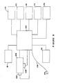
- FIG. 8 shows the functional block diagram of the automatic film processing apparatus according to the principles of the present invention.
- a central computer control device 100 controls the functioning of the system and provides for the operation of each of the particular components.
- the central computer control 100 includes conventional logic memory apparatuses and its own inherent power supply which is coupled, via a line cord 216 and plug 218 to a conventional source of AC voltage, not shown.
- the computer also provides for energizing voltage for pumps 104 and 190, the heater and blower assembly 88, the film agitation motor 116, the linear valve motor 176, liquid crystal display 18, the reservoir heater 206, temperature sensor 204 and agitator motor 208 and the purge valve 94 and are all controlled through the central computer and function in accordance with a software program, all of which is conventional and known in the art.
- a software program all of which is conventional and known in the art.
- Each of the components utilized herein are of standard components.
- the drive components and sensors are standard components which may be readily purchased.
- the linear control valve has been described herein in detail since it is not a part which may be purchased but has been conceived by the inventor herein.
Landscapes
- Physics & Mathematics (AREA)
- General Physics & Mathematics (AREA)
- Feeding, Discharge, Calcimining, Fusing, And Gas-Generation Devices (AREA)
- Photographic Processing Devices Using Wet Methods (AREA)
Applications Claiming Priority (2)
| Application Number | Priority Date | Filing Date | Title |
|---|---|---|---|
| US07/316,772 US4890131A (en) | 1989-02-28 | 1989-02-28 | Automatic film processors |
| US316772 | 1994-10-03 |
Publications (3)
| Publication Number | Publication Date |
|---|---|
| EP0385768A2 true EP0385768A2 (de) | 1990-09-05 |
| EP0385768A3 EP0385768A3 (de) | 1991-09-18 |
| EP0385768B1 EP0385768B1 (de) | 1995-05-03 |
Family
ID=23230614
Family Applications (1)
| Application Number | Title | Priority Date | Filing Date |
|---|---|---|---|
| EP90302169A Expired - Lifetime EP0385768B1 (de) | 1989-02-28 | 1990-02-28 | Automatisches Filmentwicklungsgerät |
Country Status (4)
| Country | Link |
|---|---|
| US (1) | US4890131A (de) |
| EP (1) | EP0385768B1 (de) |
| DE (1) | DE69019047T2 (de) |
| HK (1) | HK139896A (de) |
Families Citing this family (5)
| Publication number | Priority date | Publication date | Assignee | Title |
|---|---|---|---|---|
| GB9117940D0 (en) * | 1991-08-20 | 1991-10-09 | Kodak Ltd | Processing of photographic film |
| US5379086A (en) * | 1993-06-16 | 1995-01-03 | Kuzyk; Roman | Automatic photo-chemical replenishment with batch processing |
| ES2078873B1 (es) * | 1993-10-06 | 1997-10-16 | Felipe Gregorio Ramos | Procedimiento de revelado y maquina para ejecutar dicho procedimiento. |
| US5539503A (en) * | 1994-12-19 | 1996-07-23 | Hewlett-Packard Company | Magnetic drive for a liquid toner cartridge and the liquid supply system for the cartridge |
| US7252679B2 (en) * | 2001-09-13 | 2007-08-07 | Cordis Corporation | Stent with angulated struts |
Family Cites Families (9)
| Publication number | Priority date | Publication date | Assignee | Title |
|---|---|---|---|---|
| US3698307A (en) * | 1971-02-19 | 1972-10-17 | Theodore A Reichardt | Photographic print and film processing machine |
| US4035818A (en) * | 1974-12-11 | 1977-07-12 | The King Concept Corporation | Color print or film processor |
| GB1552329A (en) * | 1976-08-11 | 1979-09-12 | Paterson Prod Ltd | Drum processing apparatus |
| US4131868A (en) * | 1977-03-07 | 1978-12-26 | Gte Sylvania Incorporated | Incandescent lamp socket having overtemperature protector |
| US4248514A (en) * | 1979-10-10 | 1981-02-03 | Watkins James L | Photographic processing apparatus |
| DE3163970D1 (en) * | 1980-06-26 | 1984-07-12 | Jobo Labortech | Device for the development of photographic material |
| EP0120839A1 (de) * | 1982-10-08 | 1984-10-10 | Elektrotechnisch Bureau Moekotte B.V. | Gerät zur entwicklung fotografischer bilder und streifen |
| US4453817A (en) * | 1982-11-15 | 1984-06-12 | Clark Warren P | Automatic photographic processing apparatus utilizing a microcomputer |
| FR2583535B1 (fr) * | 1985-06-18 | 1988-02-12 | Rouault Regis | Appareil de developpement de surfaces photographiques sensibles ou analogues. |
-
1989
- 1989-02-28 US US07/316,772 patent/US4890131A/en not_active Ceased
-
1990
- 1990-02-28 EP EP90302169A patent/EP0385768B1/de not_active Expired - Lifetime
- 1990-02-28 DE DE69019047T patent/DE69019047T2/de not_active Expired - Fee Related
-
1996
- 1996-07-25 HK HK139896A patent/HK139896A/en not_active IP Right Cessation
Also Published As
| Publication number | Publication date |
|---|---|
| US4890131A (en) | 1989-12-26 |
| DE69019047T2 (de) | 1996-01-25 |
| HK139896A (en) | 1996-08-02 |
| DE69019047D1 (de) | 1995-06-08 |
| EP0385768B1 (de) | 1995-05-03 |
| EP0385768A3 (de) | 1991-09-18 |
Similar Documents
| Publication | Publication Date | Title |
|---|---|---|
| US4035818A (en) | Color print or film processor | |
| USRE34188E (en) | Automatic film processors | |
| US3623416A (en) | Processing system for photographic material | |
| US4269501A (en) | Drum for an automatic photographic processing system | |
| US3747499A (en) | Automatic film processing system and apparatus for x-ray film and the like | |
| US4890131A (en) | Automatic film processors | |
| US3545364A (en) | Photographic processing apparatus | |
| CA1168553A (en) | Material processing apparatus | |
| EP0599988B1 (de) | Tragbare filmentwicklungsvorrichtung | |
| US4248514A (en) | Photographic processing apparatus | |
| US4888607A (en) | Photograph processing method and apparatus | |
| US5502534A (en) | Automated photo developing machine | |
| US3626834A (en) | Photographic print developing unit | |
| IL30148A (en) | Photomaterial processing device | |
| US3383996A (en) | Portable daylight film processor | |
| US5790914A (en) | Photographic processor and method of operation | |
| GB2068782A (en) | Developing apparatus for photographic sheet or strip material | |
| US4754298A (en) | Disc film developing treatment apparatus | |
| US5867747A (en) | Automatic film processor | |
| GB1582648A (en) | Photographic processing apparatus | |
| JPH03100650A (ja) | 処理槽ユニット | |
| KR200191220Y1 (ko) | 반자동 필름 현상기 | |
| JPH10111550A (ja) | 写真処理装置及びその処理 | |
| EP0833199B1 (de) | Photographisches Entwicklungsgerät | |
| JP3519156B2 (ja) | 処理装置 |
Legal Events
| Date | Code | Title | Description |
|---|---|---|---|
| PUAI | Public reference made under article 153(3) epc to a published international application that has entered the european phase |
Free format text: ORIGINAL CODE: 0009012 |
|
| AK | Designated contracting states |
Kind code of ref document: A2 Designated state(s): DE FR GB IT |
|
| PUAL | Search report despatched |
Free format text: ORIGINAL CODE: 0009013 |
|
| AK | Designated contracting states |
Kind code of ref document: A3 Designated state(s): DE FR GB IT |
|
| 17P | Request for examination filed |
Effective date: 19920310 |
|
| 17Q | First examination report despatched |
Effective date: 19930526 |
|
| GRAA | (expected) grant |
Free format text: ORIGINAL CODE: 0009210 |
|
| AK | Designated contracting states |
Kind code of ref document: B1 Designated state(s): DE FR GB IT |
|
| PG25 | Lapsed in a contracting state [announced via postgrant information from national office to epo] |
Ref country code: IT Free format text: LAPSE BECAUSE OF FAILURE TO SUBMIT A TRANSLATION OF THE DESCRIPTION OR TO PAY THE FEE WITHIN THE PRE;WARNING: LAPSES OF ITALIAN PATENTS WITH EFFECTIVE DATE BEFORE 2007 MAY HAVE OCCURRED AT ANY TIME BEFORE 2007. THE CORRECT EFFECTIVE DATE MAY BE DIFFERENT FROM THE ONE RECORDED.SCRIBED TIME-LIMIT Effective date: 19950503 Ref country code: FR Effective date: 19950503 |
|
| REF | Corresponds to: |
Ref document number: 69019047 Country of ref document: DE Date of ref document: 19950608 |
|
| EN | Fr: translation not filed | ||
| PLBE | No opposition filed within time limit |
Free format text: ORIGINAL CODE: 0009261 |
|
| STAA | Information on the status of an ep patent application or granted ep patent |
Free format text: STATUS: NO OPPOSITION FILED WITHIN TIME LIMIT |
|
| 26N | No opposition filed | ||
| PGFP | Annual fee paid to national office [announced via postgrant information from national office to epo] |
Ref country code: GB Payment date: 20010219 Year of fee payment: 12 |
|
| PGFP | Annual fee paid to national office [announced via postgrant information from national office to epo] |
Ref country code: DE Payment date: 20010228 Year of fee payment: 12 |
|
| REG | Reference to a national code |
Ref country code: GB Ref legal event code: IF02 |
|
| PG25 | Lapsed in a contracting state [announced via postgrant information from national office to epo] |
Ref country code: GB Free format text: LAPSE BECAUSE OF NON-PAYMENT OF DUE FEES Effective date: 20020228 |
|
| PG25 | Lapsed in a contracting state [announced via postgrant information from national office to epo] |
Ref country code: DE Free format text: LAPSE BECAUSE OF NON-PAYMENT OF DUE FEES Effective date: 20020903 |
|
| GBPC | Gb: european patent ceased through non-payment of renewal fee |
Effective date: 20020228 |