EP0388379A1 - A door lock apparatus - Google Patents
A door lock apparatus Download PDFInfo
- Publication number
- EP0388379A1 EP0388379A1 EP90850055A EP90850055A EP0388379A1 EP 0388379 A1 EP0388379 A1 EP 0388379A1 EP 90850055 A EP90850055 A EP 90850055A EP 90850055 A EP90850055 A EP 90850055A EP 0388379 A1 EP0388379 A1 EP 0388379A1
- Authority
- EP
- European Patent Office
- Prior art keywords
- catch
- lock apparatus
- latch bolt
- receiver
- door
- Prior art date
- Legal status (The legal status is an assumption and is not a legal conclusion. Google has not performed a legal analysis and makes no representation as to the accuracy of the status listed.)
- Granted
Links
- 239000002184 metal Substances 0.000 claims description 4
- 230000004913 activation Effects 0.000 claims description 2
- 238000004880 explosion Methods 0.000 description 2
- 239000000779 smoke Substances 0.000 description 2
- 230000003213 activating effect Effects 0.000 description 1
- QVGXLLKOCUKJST-UHFFFAOYSA-N atomic oxygen Chemical compound [O] QVGXLLKOCUKJST-UHFFFAOYSA-N 0.000 description 1
- 230000000903 blocking effect Effects 0.000 description 1
- 238000007664 blowing Methods 0.000 description 1
- 238000012986 modification Methods 0.000 description 1
- 230000004048 modification Effects 0.000 description 1
- 229910052760 oxygen Inorganic materials 0.000 description 1
- 239000001301 oxygen Substances 0.000 description 1
- 230000000630 rising effect Effects 0.000 description 1
Images


Classifications
-
- E—FIXED CONSTRUCTIONS
- E05—LOCKS; KEYS; WINDOW OR DOOR FITTINGS; SAFES
- E05B—LOCKS; ACCESSORIES THEREFOR; HANDCUFFS
- E05B47/00—Operating or controlling locks or other fastening devices by electric or magnetic means
- E05B47/0001—Operating or controlling locks or other fastening devices by electric or magnetic means with electric actuators; Constructional features thereof
- E05B47/0002—Operating or controlling locks or other fastening devices by electric or magnetic means with electric actuators; Constructional features thereof with electromagnets
-
- E—FIXED CONSTRUCTIONS
- E05—LOCKS; KEYS; WINDOW OR DOOR FITTINGS; SAFES
- E05B—LOCKS; ACCESSORIES THEREFOR; HANDCUFFS
- E05B47/00—Operating or controlling locks or other fastening devices by electric or magnetic means
- E05B47/06—Controlling mechanically-operated bolts by electro-magnetically-operated detents
- E05B47/0603—Controlling mechanically-operated bolts by electro-magnetically-operated detents the detent moving rectilinearly
-
- E—FIXED CONSTRUCTIONS
- E05—LOCKS; KEYS; WINDOW OR DOOR FITTINGS; SAFES
- E05B—LOCKS; ACCESSORIES THEREFOR; HANDCUFFS
- E05B65/00—Locks or fastenings for special use
- E05B65/10—Locks or fastenings for special use for panic or emergency doors
- E05B65/104—Locks or fastenings for special use for panic or emergency doors actuated in response to heat, e.g. with fusible element, bimetal, memory shape or swelling material
-
- E—FIXED CONSTRUCTIONS
- E05—LOCKS; KEYS; WINDOW OR DOOR FITTINGS; SAFES
- E05B—LOCKS; ACCESSORIES THEREFOR; HANDCUFFS
- E05B47/00—Operating or controlling locks or other fastening devices by electric or magnetic means
- E05B2047/0048—Circuits, feeding, monitoring
- E05B2047/0057—Feeding
- E05B2047/0064—Feeding by solar cells
-
- E—FIXED CONSTRUCTIONS
- E05—LOCKS; KEYS; WINDOW OR DOOR FITTINGS; SAFES
- E05B—LOCKS; ACCESSORIES THEREFOR; HANDCUFFS
- E05B47/00—Operating or controlling locks or other fastening devices by electric or magnetic means
- E05B47/0001—Operating or controlling locks or other fastening devices by electric or magnetic means with electric actuators; Constructional features thereof
- E05B47/0002—Operating or controlling locks or other fastening devices by electric or magnetic means with electric actuators; Constructional features thereof with electromagnets
- E05B47/0003—Operating or controlling locks or other fastening devices by electric or magnetic means with electric actuators; Constructional features thereof with electromagnets having a movable core
- E05B47/0004—Operating or controlling locks or other fastening devices by electric or magnetic means with electric actuators; Constructional features thereof with electromagnets having a movable core said core being linearly movable
-
- E—FIXED CONSTRUCTIONS
- E05—LOCKS; KEYS; WINDOW OR DOOR FITTINGS; SAFES
- E05B—LOCKS; ACCESSORIES THEREFOR; HANDCUFFS
- E05B63/00—Locks or fastenings with special structural characteristics
- E05B63/18—Locks or fastenings with special structural characteristics with arrangements independent of the locking mechanism for retaining the bolt or latch in the retracted position
-
- Y—GENERAL TAGGING OF NEW TECHNOLOGICAL DEVELOPMENTS; GENERAL TAGGING OF CROSS-SECTIONAL TECHNOLOGIES SPANNING OVER SEVERAL SECTIONS OF THE IPC; TECHNICAL SUBJECTS COVERED BY FORMER USPC CROSS-REFERENCE ART COLLECTIONS [XRACs] AND DIGESTS
- Y10—TECHNICAL SUBJECTS COVERED BY FORMER USPC
- Y10S—TECHNICAL SUBJECTS COVERED BY FORMER USPC CROSS-REFERENCE ART COLLECTIONS [XRACs] AND DIGESTS
- Y10S292/00—Closure fasteners
- Y10S292/25—Remote control
-
- Y—GENERAL TAGGING OF NEW TECHNOLOGICAL DEVELOPMENTS; GENERAL TAGGING OF CROSS-SECTIONAL TECHNOLOGIES SPANNING OVER SEVERAL SECTIONS OF THE IPC; TECHNICAL SUBJECTS COVERED BY FORMER USPC CROSS-REFERENCE ART COLLECTIONS [XRACs] AND DIGESTS
- Y10—TECHNICAL SUBJECTS COVERED BY FORMER USPC
- Y10S—TECHNICAL SUBJECTS COVERED BY FORMER USPC CROSS-REFERENCE ART COLLECTIONS [XRACs] AND DIGESTS
- Y10S292/00—Closure fasteners
- Y10S292/66—Thermally controlled mechanism
-
- Y—GENERAL TAGGING OF NEW TECHNOLOGICAL DEVELOPMENTS; GENERAL TAGGING OF CROSS-SECTIONAL TECHNOLOGIES SPANNING OVER SEVERAL SECTIONS OF THE IPC; TECHNICAL SUBJECTS COVERED BY FORMER USPC CROSS-REFERENCE ART COLLECTIONS [XRACs] AND DIGESTS
- Y10—TECHNICAL SUBJECTS COVERED BY FORMER USPC
- Y10T—TECHNICAL SUBJECTS COVERED BY FORMER US CLASSIFICATION
- Y10T292/00—Closure fasteners
- Y10T292/08—Bolts
- Y10T292/096—Sliding
- Y10T292/0969—Spring projected
- Y10T292/097—Operating means
- Y10T292/0994—Lever
-
- Y—GENERAL TAGGING OF NEW TECHNOLOGICAL DEVELOPMENTS; GENERAL TAGGING OF CROSS-SECTIONAL TECHNOLOGIES SPANNING OVER SEVERAL SECTIONS OF THE IPC; TECHNICAL SUBJECTS COVERED BY FORMER USPC CROSS-REFERENCE ART COLLECTIONS [XRACs] AND DIGESTS
- Y10—TECHNICAL SUBJECTS COVERED BY FORMER USPC
- Y10T—TECHNICAL SUBJECTS COVERED BY FORMER US CLASSIFICATION
- Y10T292/00—Closure fasteners
- Y10T292/08—Bolts
- Y10T292/096—Sliding
- Y10T292/1014—Operating means
- Y10T292/1021—Motor
-
- Y—GENERAL TAGGING OF NEW TECHNOLOGICAL DEVELOPMENTS; GENERAL TAGGING OF CROSS-SECTIONAL TECHNOLOGIES SPANNING OVER SEVERAL SECTIONS OF THE IPC; TECHNICAL SUBJECTS COVERED BY FORMER USPC CROSS-REFERENCE ART COLLECTIONS [XRACs] AND DIGESTS
- Y10—TECHNICAL SUBJECTS COVERED BY FORMER USPC
- Y10T—TECHNICAL SUBJECTS COVERED BY FORMER US CLASSIFICATION
- Y10T70/00—Locks
- Y10T70/50—Special application
- Y10T70/5889—For automotive vehicles
- Y10T70/5973—Remote control
Definitions
- the present invention relates to a door lock apparatus, comprising a latch bolt, which can be actuated from an operable position by means of a door handle driver against the action of a spring means.
- doors may be opened and closed without the need for manipulation of a pivotally mounted handle for a latch bolt.
- One field of application for such doors is, for example, for hospital wards and similar premises where one wants to be able to open and close a door with a minimum of noise.
- Such regulations are normal for hospital ward doors, because hospital ward doors normally contain equipment for administration of oxygen.
- One object of the present invention is to provide a door lock apparatus, which meets both the demands for silent passage through the door, and the demands for a blocking facility in case of a fire.
- a catch means for the latch bolt said means being biased by a second spring means into its catch position from which it can be displaced by means of an actuator which is connected to a wireless signal receiver, and an alarm detector, remotely placed from the lock apparatus, is connected to a wireless signal transmitter, which is adapted to be activated when the detector detects a state of alarm, so that a signal is sent which is detectable by the receiver at the lock apparatus, for displacing the catch means out of its catch position.
- the actuator comprises an electromagnet.
- the second spring means comprises a bimetal or memory metal spring, which is connected to the catch means and adapted to displace it out of its catch position when the temperature rises above a certain predetermined level.
- the receiver obtains a supply of current via a solar cell in connection with a rechargeable battery.
- the transmitter is connected to means for activation of more than one selectable transmitter frequency.
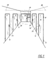
- the corridor shown in Fig. 1 is assumed to belong to a wing in a hospital.
- the corridor is ended by an entrance and exit door 10 into an elevator shaft or staircase and is provided with four doors 11 into a corresponding number of wards.
- the doors 11 are conventional hinges 12 and handles 13.
- the doors which are equipped with lock apparatuses 14 according to the invention, shown in Fig. 2 and 3 with a latch bolt 15 and a handle driver 16.
- the lock apparatus 14 is also conventionally provided with two spring means 17 and 18 for pressing the latch bolt 15 axially out into an opening in the forend plate 14a and for rotation of the handle driver 16 to its normal position of rest, respectively.
- the latch bolt 15 comprises a shaft 19 and a head 20, which forms the attack surface for the actuator arm 16a of the handle driver 16.
- the latch bolt is guided between two cross bolts 21, 22, which together with the edges of the forend plate 14 defines the axial path of movement of the latch bolt.
- the handle driver 16 is pivotally journalled in the lock apparatus and may be operated by means of a handle, which is not shown in the drawings, via a square section bolt 23, so that the latch bolt can be pulled into the lock housing as is shown in Fig. 2, when the door handle is operated, i.e. when the handle rower is turned clockwise in the drawings.
- the lock housing 14 is also provided with a catch means which comprises an electromagnet 24 and catch which can be manipulated by said catch 25.
- the catch means is axially movable in a channel 26 in the electromagnet 24 and normally biased by means of a spring 27, made of memory metal, in the direction downward in Fig. 2 and 3.
- the head 20 of the latch bolt 15 is provided with a bevelling 20a, the head can be moved past the catch 25 to the position shown in Fig. 3, wherein the latch bolt is in a latching position.
- the latch bolt is held in the position shown in Fig. 3, in order to facilitate opening and closing of the door without disturbing noise.
- the latch bolt in case of a fire, the latch bolt must be operable, in order to prevent that the door is blown open by a rapid change in pressure, e.g. because of an explosion in the room enclosed by said door.
- Fig. 1 shows, smoke and fire detectors 28 are placed in the rooms which are enclosed by the doors 11.
- the detectors 28 are connected to a common alarm central 29.
- This central is provided with a wireless signal transmitter, well known in the art, and which does not need to be elaborately described.
- the transmitter When the alarm central 29 indicates a state of smoke or fire, the transmitter is activated and sends a wireless signal in the direction of the corridor. This signal is detected by a wireless signal receiver 30 placed on each respective door 11.
- the transmitter may be so arranged that it transmits select signals to individual doors, or alternatively, signals which are detectable by all signal receivers 30.
- the signal receiver 30 is shown in greater detail in Fig. 2 and 3 and is placed adjacent the lock housing 14, in order to minimize the wire laying.
- One wire 31 runs between the receiver and the electromagnet 24 mounted within the lock housing.
- a relay in the receiver 30 is activated by the wireless signal and supplies activating current to the electromagnet from a source of energy mounted within the receiver.
- the electromagnet 24 now pulls the catch 25 against the action of the bimetal spring, and the latch bolt 15 can be pushed out into a striking plate in the adjacent door frame (see Fig. 2), by the action of the hairpin spring 17.
- the door can be opened conventionally by manipulation of the latch bolt by means of the handle driver 16.
- the alarm condition can be interrupted at the alarm central 29. This breaks the current to the electromagnet 24 and the latch bolt 15 will return to the position shown in Fig. 3, the next time the trigger is manipulated for opening of the door.
- the memory metal spring 27 is adapted to react upon the rising temperature and pull the catch 25 out of its catch position.
- the receiver 30 is provided with a front wall 33 which normally is locked by a lock 32.
- a solar cell 34 is mounted on the outside of said front wall.
- the solar cell is connected to a rechargeable battery, which is adapted to sustain a supply of energy to the electromagnet 24 during a temporary break in the supply of energy, when the solar cell does not get enough light.
- the wireless communication between the transmitter and the receiver will be made by radio waves.
- Other types of carrier waves are also possible.
- the apparatus according to the invention may be adapted for other fields of use than shown, e.g. in factory plants and laboratories.
- the lock apparatus and the catch means can be designed differently than shown.
Landscapes
- Physics & Mathematics (AREA)
- Electromagnetism (AREA)
- Business, Economics & Management (AREA)
- Emergency Management (AREA)
- Lock And Its Accessories (AREA)
- Refrigerator Housings (AREA)
- Casings For Electric Apparatus (AREA)
- Vehicle Step Arrangements And Article Storage (AREA)
- Coin-Freed Apparatuses For Hiring Articles (AREA)
- Closing And Opening Devices For Wings, And Checks For Wings (AREA)
- Patch Boards (AREA)
- Special Wing (AREA)
- Alarm Systems (AREA)
- Fire Alarms (AREA)
Abstract
Description
- The present invention relates to a door lock apparatus, comprising a latch bolt, which can be actuated from an operable position by means of a door handle driver against the action of a spring means.
- In many applications it is desirable that doors may be opened and closed without the need for manipulation of a pivotally mounted handle for a latch bolt. One field of application for such doors is, for example, for hospital wards and similar premises where one wants to be able to open and close a door with a minimum of noise. In relation to this, a problem exists if fire and building regulations requires that a latch bolt must be present to prevent the door from blowing up, in case of an explosion in the area enclosed by the door. Such regulations are normal for hospital ward doors, because hospital ward doors normally contain equipment for administration of oxygen.
- One object of the present invention is to provide a door lock apparatus, which meets both the demands for silent passage through the door, and the demands for a blocking facility in case of a fire.
- These objects are accomplished according to the invention, by providing it with a catch means for the latch bolt, said means being biased by a second spring means into its catch position from which it can be displaced by means of an actuator which is connected to a wireless signal receiver, and an alarm detector, remotely placed from the lock apparatus, is connected to a wireless signal transmitter, which is adapted to be activated when the detector detects a state of alarm, so that a signal is sent which is detectable by the receiver at the lock apparatus, for displacing the catch means out of its catch position.
- According to one preferable embodiment of the invention, the actuator comprises an electromagnet.
- Preferably, the second spring means comprises a bimetal or memory metal spring, which is connected to the catch means and adapted to displace it out of its catch position when the temperature rises above a certain predetermined level.
- Preferably, the receiver obtains a supply of current via a solar cell in connection with a rechargeable battery.
- According to another preferable embodiment of the invention, the transmitter is connected to means for activation of more than one selectable transmitter frequency.
- One embodiment of the invention will now be described in more detail in the following, with reference to the accompanying drawings, in which
- Fig. 1 shows a hospital ward corridor with doors equipped with a lock apparatus according to the invention,
- Fig. 2 in a larger scale shows the lock apparatus according to the invention, in a first mode of use, and
- Fig. 3 shows the lock apparatus in Fig. 2 in a second mode of use.
- The corridor shown in Fig. 1 is assumed to belong to a wing in a hospital. The corridor is ended by an entrance and
exit door 10 into an elevator shaft or staircase and is provided with fourdoors 11 into a corresponding number of wards. Thedoors 11 areconventional hinges 12 and handles 13. - Normally these doors lack any latch bolt and trigger. Also, it exists doors having a lock apparatus where the latch bolt is mechanically blocked in an inner position, so that no latch bolt movement will be able to create any noise while opening and closing these doors.
- The doors which are equipped with
lock apparatuses 14 according to the invention, shown in Fig. 2 and 3 with alatch bolt 15 and ahandle driver 16. Thelock apparatus 14 is also conventionally provided with two spring means 17 and 18 for pressing thelatch bolt 15 axially out into an opening in theforend plate 14a and for rotation of thehandle driver 16 to its normal position of rest, respectively. Thelatch bolt 15 comprises ashaft 19 and ahead 20, which forms the attack surface for theactuator arm 16a of thehandle driver 16. The latch bolt is guided between twocross bolts forend plate 14 defines the axial path of movement of the latch bolt. - The
handle driver 16 is pivotally journalled in the lock apparatus and may be operated by means of a handle, which is not shown in the drawings, via asquare section bolt 23, so that the latch bolt can be pulled into the lock housing as is shown in Fig. 2, when the door handle is operated, i.e. when the handle rower is turned clockwise in the drawings. - The
lock housing 14 is also provided with a catch means which comprises anelectromagnet 24 and catch which can be manipulated by saidcatch 25. The catch means is axially movable in achannel 26 in theelectromagnet 24 and normally biased by means of aspring 27, made of memory metal, in the direction downward in Fig. 2 and 3. - Because the
head 20 of thelatch bolt 15 is provided with a bevelling 20a, the head can be moved past thecatch 25 to the position shown in Fig. 3, wherein the latch bolt is in a latching position. - During normal conditions, the latch bolt is held in the position shown in Fig. 3, in order to facilitate opening and closing of the door without disturbing noise.
- However, in case of a fire, the latch bolt must be operable, in order to prevent that the door is blown open by a rapid change in pressure, e.g. because of an explosion in the room enclosed by said door.
- As Fig. 1 shows, smoke and
fire detectors 28 are placed in the rooms which are enclosed by thedoors 11. Thedetectors 28 are connected to a common alarm central 29. This central is provided with a wireless signal transmitter, well known in the art, and which does not need to be elaborately described. - When the alarm central 29 indicates a state of smoke or fire, the transmitter is activated and sends a wireless signal in the direction of the corridor. This signal is detected by a
wireless signal receiver 30 placed on eachrespective door 11. - In this respect, the transmitter may be so arranged that it transmits select signals to individual doors, or alternatively, signals which are detectable by all
signal receivers 30. - The
signal receiver 30 is shown in greater detail in Fig. 2 and 3 and is placed adjacent thelock housing 14, in order to minimize the wire laying. Onewire 31 runs between the receiver and theelectromagnet 24 mounted within the lock housing. A relay in thereceiver 30 is activated by the wireless signal and supplies activating current to the electromagnet from a source of energy mounted within the receiver. Theelectromagnet 24 now pulls thecatch 25 against the action of the bimetal spring, and thelatch bolt 15 can be pushed out into a striking plate in the adjacent door frame (see Fig. 2), by the action of thehairpin spring 17. - In this position, the door can be opened conventionally by manipulation of the latch bolt by means of the
handle driver 16. - In case of a false alarm or similar, the alarm condition can be interrupted at the alarm central 29. This breaks the current to the
electromagnet 24 and thelatch bolt 15 will return to the position shown in Fig. 3, the next time the trigger is manipulated for opening of the door. - If the fire should be so intensive that the heat will damage the electrical components in the
receiver 30 or thelock housing 14, the current to the electromagnet might be broken. Now, if the door would be opened by means of the handle, the latch bolt could accidentally be caught by thecatch 25 in its inoperative position, which would not be desirable. However, thememory metal spring 27 is adapted to react upon the rising temperature and pull thecatch 25 out of its catch position. - The
receiver 30 is provided with afront wall 33 which normally is locked by alock 32. Asolar cell 34 is mounted on the outside of said front wall. The solar cell is connected to a rechargeable battery, which is adapted to sustain a supply of energy to theelectromagnet 24 during a temporary break in the supply of energy, when the solar cell does not get enough light. - Preferably, the wireless communication between the transmitter and the receiver will be made by radio waves. Other types of carrier waves are also possible.
- The invention is not limited to the above described embodiment, but several modifications are possible within the scope of the accompanying claims. For example, the apparatus according to the invention may be adapted for other fields of use than shown, e.g. in factory plants and laboratories. The lock apparatus and the catch means can be designed differently than shown.
Claims (5)
Priority Applications (1)
| Application Number | Priority Date | Filing Date | Title |
|---|---|---|---|
| AT90850055T ATE95877T1 (en) | 1989-02-10 | 1990-02-07 | LOCKING DEVICE FOR A DOOR. |
Applications Claiming Priority (2)
| Application Number | Priority Date | Filing Date | Title |
|---|---|---|---|
| SE8900450 | 1989-02-10 | ||
| SE8900450A SE463678B (en) | 1989-02-10 | 1989-02-10 | DEVICE AT LAASHUS |
Publications (2)
| Publication Number | Publication Date |
|---|---|
| EP0388379A1 true EP0388379A1 (en) | 1990-09-19 |
| EP0388379B1 EP0388379B1 (en) | 1993-10-13 |
Family
ID=20375000
Family Applications (1)
| Application Number | Title | Priority Date | Filing Date |
|---|---|---|---|
| EP90850055A Expired - Lifetime EP0388379B1 (en) | 1989-02-10 | 1990-02-07 | A door lock apparatus |
Country Status (7)
| Country | Link |
|---|---|
| US (1) | US5009456A (en) |
| EP (1) | EP0388379B1 (en) |
| AT (1) | ATE95877T1 (en) |
| DE (1) | DE69003844T2 (en) |
| FI (1) | FI90274C (en) |
| NO (1) | NO900595L (en) |
| SE (1) | SE463678B (en) |
Cited By (8)
| Publication number | Priority date | Publication date | Assignee | Title |
|---|---|---|---|---|
| WO1993020317A1 (en) * | 1992-04-07 | 1993-10-14 | Dorgard Ltd | Apparatus for actuating a safety device |
| EP1113134A3 (en) * | 1999-12-22 | 2002-04-10 | Mila Hardware Limited | Lock mechanism |
| EP1418297A1 (en) * | 2002-11-01 | 2004-05-12 | M.H.B. B.V. | Door provided with at least one latch arranged at a distance from a door top, system of two doors arranged next to each other, and assembly provided with at least one door |
| EP1420134A3 (en) * | 2002-11-18 | 2007-02-28 | C.R. Laurence Company, Inc. | Door handle actuated electronic egress system |
| EP1767732A3 (en) * | 2005-09-13 | 2009-05-06 | Eaton Corporation | Lock device and system employing a door lock device |
| CN102733677A (en) * | 2012-06-05 | 2012-10-17 | 莫广飞 | Invisible remote control lock |
| EP2853662A1 (en) | 2013-09-27 | 2015-04-01 | Sm Feu | Lock with a thermal trigger |
| WO2017183966A1 (en) * | 2016-04-19 | 2017-10-26 | Remko Mark B.V. | A door provided with at least one latch |
Families Citing this family (25)
| Publication number | Priority date | Publication date | Assignee | Title |
|---|---|---|---|---|
| US5531086A (en) * | 1994-08-15 | 1996-07-02 | Bryant; Randy K. | Keyless entry deadbolt lock |
| AUPM920394A0 (en) * | 1994-11-01 | 1994-11-24 | Technosearch Pty. Limited | Remote lock control means |
| US5911460A (en) * | 1997-02-25 | 1999-06-15 | Georgia Tech Research Corp. | Jamb pocket latch bolt assembly release apparatus |
| US5905446A (en) * | 1997-03-24 | 1999-05-18 | Diebold, Incorporated | Electronic key system |
| US6135512A (en) * | 1998-06-12 | 2000-10-24 | Galvin; Donna | Automatic door latch |
| US6185852B1 (en) * | 1998-10-26 | 2001-02-13 | Ronald F. Whalen | Electronic weapon safety system |
| AU6533400A (en) | 1999-08-10 | 2001-03-05 | Stanley Works Pty. Ltd., The | Power door kit |
| DE10038376C2 (en) * | 2000-08-07 | 2003-04-30 | Zangenstein Elektro | Door lock for the door of an electrical household appliance |
| US20030103472A1 (en) * | 2001-09-30 | 2003-06-05 | Ronald Taylor | RF wireless access control for locking system |
| US7248836B2 (en) * | 2001-09-30 | 2007-07-24 | Schlage Lock Company | RF channel linking method and system |
| US20030074936A1 (en) * | 2001-09-30 | 2003-04-24 | Fred Conforti | Door wireless access control system including reader, lock, and wireless access control electronics including wireless transceiver |
| US7289764B2 (en) | 2001-09-30 | 2007-10-30 | Harrow Products, Llc | Cardholder interface for an access control system |
| US7346331B2 (en) * | 2001-09-30 | 2008-03-18 | Harrow Products, Llc | Power management for locking system |
| US20030096607A1 (en) * | 2001-09-30 | 2003-05-22 | Ronald Taylor | Maintenance/trouble signals for a RF wireless locking system |
| US6950033B1 (en) * | 2003-01-22 | 2005-09-27 | Louis N Guyre | Door bolt alarm |
| DE10321802B4 (en) * | 2003-05-14 | 2012-09-13 | Dorma Gmbh + Co. Kg | Safety device for a door, in particular fire door or the like |
| US7747286B2 (en) * | 2004-01-20 | 2010-06-29 | Harrow Products Llc | Wireless access control system with energy-saving piezo-electric locking |
| US7014226B1 (en) * | 2004-09-01 | 2006-03-21 | Soca Technology Co., Ltd. | Electromagnetic lock device |
| US20080041445A1 (en) * | 2006-04-18 | 2008-02-21 | Miller John J Jr | Energy capture system |
| US20090315669A1 (en) * | 2006-07-04 | 2009-12-24 | Robert Bruce Lang | Safety system |
| US20110221211A1 (en) * | 2010-03-09 | 2011-09-15 | Corby Weron | Self-Locking Latch for Window Sash |
| US20120091737A1 (en) * | 2010-10-15 | 2012-04-19 | Joseph Conley | Earthquake Cabinet Safety |
| US8881637B2 (en) | 2013-03-15 | 2014-11-11 | Sargent Manufacturing Company | Door lock access control component mounting |
| CN104131744A (en) * | 2014-07-16 | 2014-11-05 | 黄进平 | Antitheft door lock free of key holes |
| US11989988B2 (en) | 2020-10-19 | 2024-05-21 | Zephyr Lock, Llc | Electronic lock with photovoltaic cells |
Citations (3)
| Publication number | Priority date | Publication date | Assignee | Title |
|---|---|---|---|---|
| GB1511519A (en) * | 1974-11-20 | 1978-05-17 | Jank W | Apparatus for electrically monitoring closure of a lock |
| DE2752089A1 (en) * | 1976-12-06 | 1978-06-08 | Titan Tovarna Kovinskih Izdelk | Profiled cylinder lock within mortice lock - has additional lever and bolt indicating mortice lock state |
| GB2093520A (en) * | 1981-01-14 | 1982-09-02 | Wormald Int | Combination lock monitoring system |
Family Cites Families (6)
| Publication number | Priority date | Publication date | Assignee | Title |
|---|---|---|---|---|
| US2382062A (en) * | 1943-04-26 | 1945-08-14 | Ferro Stamping & Mfg Company | Latch |
| US4200954A (en) * | 1976-04-13 | 1980-05-06 | Mccabe Francis J | Telescoping heat responsive releasing means |
| US4663626A (en) * | 1985-04-11 | 1987-05-05 | Smith Eldon L | Remote control vehicle unlocking device |
| US4726613A (en) * | 1986-03-03 | 1988-02-23 | Best Lock Corporation | Fire safety door latch |
| ES2026498T3 (en) * | 1986-08-12 | 1992-05-01 | Siemens Aktiengesellschaft | ELECTRONIC LOCKING INSTALLATION WITH AT LEAST ONE LOCK ESPECIALLY FOR AUTOMOBILES. |
| JPH0735706B2 (en) * | 1987-02-23 | 1995-04-19 | 国際技術開発株式会社 | Electric lock |
-
1989
- 1989-02-10 SE SE8900450A patent/SE463678B/en not_active IP Right Cessation
-
1990
- 1990-01-30 US US07/472,202 patent/US5009456A/en not_active Expired - Fee Related
- 1990-01-30 FI FI900459A patent/FI90274C/en not_active IP Right Cessation
- 1990-02-07 NO NO90900595A patent/NO900595L/en unknown
- 1990-02-07 AT AT90850055T patent/ATE95877T1/en active
- 1990-02-07 EP EP90850055A patent/EP0388379B1/en not_active Expired - Lifetime
- 1990-02-07 DE DE90850055T patent/DE69003844T2/en not_active Expired - Fee Related
Patent Citations (3)
| Publication number | Priority date | Publication date | Assignee | Title |
|---|---|---|---|---|
| GB1511519A (en) * | 1974-11-20 | 1978-05-17 | Jank W | Apparatus for electrically monitoring closure of a lock |
| DE2752089A1 (en) * | 1976-12-06 | 1978-06-08 | Titan Tovarna Kovinskih Izdelk | Profiled cylinder lock within mortice lock - has additional lever and bolt indicating mortice lock state |
| GB2093520A (en) * | 1981-01-14 | 1982-09-02 | Wormald Int | Combination lock monitoring system |
Cited By (12)
| Publication number | Priority date | Publication date | Assignee | Title |
|---|---|---|---|---|
| WO1993020317A1 (en) * | 1992-04-07 | 1993-10-14 | Dorgard Ltd | Apparatus for actuating a safety device |
| US5525963A (en) * | 1992-04-07 | 1996-06-11 | Purssey; Neil K. W. | Apparatus for actuating a safety device |
| EP1113134A3 (en) * | 1999-12-22 | 2002-04-10 | Mila Hardware Limited | Lock mechanism |
| EP1418297A1 (en) * | 2002-11-01 | 2004-05-12 | M.H.B. B.V. | Door provided with at least one latch arranged at a distance from a door top, system of two doors arranged next to each other, and assembly provided with at least one door |
| EP1420134A3 (en) * | 2002-11-18 | 2007-02-28 | C.R. Laurence Company, Inc. | Door handle actuated electronic egress system |
| US7347461B2 (en) | 2002-11-18 | 2008-03-25 | C.R. Laurence Company, Inc. | Door handle actuated electronic egress system |
| EP1767732A3 (en) * | 2005-09-13 | 2009-05-06 | Eaton Corporation | Lock device and system employing a door lock device |
| CN102733677A (en) * | 2012-06-05 | 2012-10-17 | 莫广飞 | Invisible remote control lock |
| EP2853662A1 (en) | 2013-09-27 | 2015-04-01 | Sm Feu | Lock with a thermal trigger |
| FR3011187A1 (en) * | 2013-09-27 | 2015-04-03 | Sm Feu | THERMAL TRIP LOCK |
| WO2017183966A1 (en) * | 2016-04-19 | 2017-10-26 | Remko Mark B.V. | A door provided with at least one latch |
| NL2016633B1 (en) * | 2016-04-19 | 2017-11-02 | Remko Mark B V | A door provided with at least one latch. |
Also Published As
| Publication number | Publication date |
|---|---|
| DE69003844D1 (en) | 1993-11-18 |
| SE8900450L (en) | 1990-08-11 |
| DE69003844T2 (en) | 1994-02-03 |
| NO900595D0 (en) | 1990-02-07 |
| NO900595L (en) | 1990-08-13 |
| EP0388379B1 (en) | 1993-10-13 |
| FI900459A0 (en) | 1990-01-30 |
| FI90274C (en) | 1994-01-10 |
| SE8900450D0 (en) | 1989-02-10 |
| US5009456A (en) | 1991-04-23 |
| ATE95877T1 (en) | 1993-10-15 |
| SE463678B (en) | 1991-01-07 |
| FI90274B (en) | 1993-09-30 |
Similar Documents
| Publication | Publication Date | Title |
|---|---|---|
| EP0388379B1 (en) | A door lock apparatus | |
| US5925861A (en) | Security door lock arrangement with magnetically operated switch in the closed door position | |
| EP2015272A2 (en) | Tamper detector for a security sensor | |
| GB2494229A (en) | A fastening device with remote monitoring | |
| EP2240918A1 (en) | A security system | |
| US20100026489A1 (en) | Security device and security system using the same | |
| US4002229A (en) | Trash chute locking system | |
| GB2223531A (en) | Security system; remote actuation of window locks | |
| US12006731B2 (en) | Touchless, pushbutton exit devices, systems and methods thereof | |
| GB2584108A (en) | Casement window handle sensor | |
| WO2002077400A2 (en) | Improvements relating to security of, and strategies for exiting, lockable enclosures | |
| US20140361896A1 (en) | Intrusion Detection System and Method thereof | |
| JP3146160U (en) | Security device | |
| GB2215387A (en) | Central locking system for buildings | |
| US7319391B2 (en) | Centralised security closure | |
| KR0175216B1 (en) | Lock device automatically released in case of emergency | |
| WO2012085606A1 (en) | Electronic home protection apparatus | |
| GB1600858A (en) | Security installation | |
| JP2001355361A (en) | Security device | |
| AU2008200701B2 (en) | A Lock with a Smoke Alarm Interface | |
| US4074247A (en) | Attack dog security system | |
| AU679357B2 (en) | Security apparatus | |
| KR200335150Y1 (en) | Electromotive window remote control system | |
| EP0589822B1 (en) | Device for opening a window or a door, especially of the sliding type | |
| JPH041389A (en) | Door with ventilating device |
Legal Events
| Date | Code | Title | Description |
|---|---|---|---|
| PUAI | Public reference made under article 153(3) epc to a published international application that has entered the european phase |
Free format text: ORIGINAL CODE: 0009012 |
|
| AK | Designated contracting states |
Kind code of ref document: A1 Designated state(s): AT BE CH DE DK ES FR GB GR IT LI LU NL |
|
| 17P | Request for examination filed |
Effective date: 19910315 |
|
| 17Q | First examination report despatched |
Effective date: 19920429 |
|
| GRAA | (expected) grant |
Free format text: ORIGINAL CODE: 0009210 |
|
| AK | Designated contracting states |
Kind code of ref document: B1 Designated state(s): AT BE CH DE DK ES FR GB GR IT LI LU NL |
|
| PG25 | Lapsed in a contracting state [announced via postgrant information from national office to epo] |
Ref country code: NL Effective date: 19931013 Ref country code: IT Free format text: LAPSE BECAUSE OF FAILURE TO SUBMIT A TRANSLATION OF THE DESCRIPTION OR TO PAY THE FEE WITHIN THE PRESCRIBED TIME-LIMIT;WARNING: LAPSES OF ITALIAN PATENTS WITH EFFECTIVE DATE BEFORE 2007 MAY HAVE OCCURRED AT ANY TIME BEFORE 2007. THE CORRECT EFFECTIVE DATE MAY BE DIFFERENT FROM THE ONE RECORDED. Effective date: 19931013 Ref country code: DK Effective date: 19931013 Ref country code: LI Effective date: 19931013 Ref country code: AT Effective date: 19931013 Ref country code: GR Free format text: LAPSE BECAUSE OF FAILURE TO SUBMIT A TRANSLATION OF THE DESCRIPTION OR TO PAY THE FEE WITHIN THE PRESCRIBED TIME-LIMIT Effective date: 19931013 Ref country code: BE Effective date: 19931013 Ref country code: ES Free format text: THE PATENT HAS BEEN ANNULLED BY A DECISION OF A NATIONAL AUTHORITY Effective date: 19931013 Ref country code: CH Effective date: 19931013 |
|
| REF | Corresponds to: |
Ref document number: 95877 Country of ref document: AT Date of ref document: 19931015 Kind code of ref document: T |
|
| REF | Corresponds to: |
Ref document number: 69003844 Country of ref document: DE Date of ref document: 19931118 |
|
| REG | Reference to a national code |
Ref country code: CH Ref legal event code: PL |
|
| ET | Fr: translation filed | ||
| PG25 | Lapsed in a contracting state [announced via postgrant information from national office to epo] |
Ref country code: LU Free format text: LAPSE BECAUSE OF NON-PAYMENT OF DUE FEES Effective date: 19940228 |
|
| NLV1 | Nl: lapsed or annulled due to failure to fulfill the requirements of art. 29p and 29m of the patents act | ||
| PLBE | No opposition filed within time limit |
Free format text: ORIGINAL CODE: 0009261 |
|
| STAA | Information on the status of an ep patent application or granted ep patent |
Free format text: STATUS: NO OPPOSITION FILED WITHIN TIME LIMIT |
|
| 26N | No opposition filed | ||
| PGFP | Annual fee paid to national office [announced via postgrant information from national office to epo] |
Ref country code: GB Payment date: 19950306 Year of fee payment: 6 |
|
| PGFP | Annual fee paid to national office [announced via postgrant information from national office to epo] |
Ref country code: FR Payment date: 19950308 Year of fee payment: 6 |
|
| PG25 | Lapsed in a contracting state [announced via postgrant information from national office to epo] |
Ref country code: GB Effective date: 19960207 |
|
| PGFP | Annual fee paid to national office [announced via postgrant information from national office to epo] |
Ref country code: DE Payment date: 19960304 Year of fee payment: 7 |
|
| GBPC | Gb: european patent ceased through non-payment of renewal fee |
Effective date: 19960207 |
|
| PG25 | Lapsed in a contracting state [announced via postgrant information from national office to epo] |
Ref country code: FR Effective date: 19961031 |
|
| REG | Reference to a national code |
Ref country code: FR Ref legal event code: ST |
|
| PG25 | Lapsed in a contracting state [announced via postgrant information from national office to epo] |
Ref country code: DE Effective date: 19971101 |