EP0389054B1 - Verborgene Vorrichtung zur Wandmontage eines Wandmöbelelementes - Google Patents
Verborgene Vorrichtung zur Wandmontage eines Wandmöbelelementes Download PDFInfo
- Publication number
- EP0389054B1 EP0389054B1 EP90200644A EP90200644A EP0389054B1 EP 0389054 B1 EP0389054 B1 EP 0389054B1 EP 90200644 A EP90200644 A EP 90200644A EP 90200644 A EP90200644 A EP 90200644A EP 0389054 B1 EP0389054 B1 EP 0389054B1
- Authority
- EP
- European Patent Office
- Prior art keywords
- plate
- core
- screw
- casing
- coupling module
- Prior art date
- Legal status (The legal status is an assumption and is not a legal conclusion. Google has not performed a legal analysis and makes no representation as to the accuracy of the status listed.)
- Expired - Lifetime
Links
- 230000008878 coupling Effects 0.000 claims abstract description 54
- 238000010168 coupling process Methods 0.000 claims abstract description 54
- 238000005859 coupling reaction Methods 0.000 claims abstract description 54
- 230000007246 mechanism Effects 0.000 claims description 16
- 238000005452 bending Methods 0.000 claims description 2
- 239000002184 metal Substances 0.000 claims description 2
- 230000014759 maintenance of location Effects 0.000 description 2
- 208000027418 Wounds and injury Diseases 0.000 description 1
- 230000006978 adaptation Effects 0.000 description 1
- 238000005352 clarification Methods 0.000 description 1
- 230000000295 complement effect Effects 0.000 description 1
- 230000006378 damage Effects 0.000 description 1
- 208000014674 injury Diseases 0.000 description 1
- 238000000926 separation method Methods 0.000 description 1
Images


Classifications
-
- A—HUMAN NECESSITIES
- A47—FURNITURE; DOMESTIC ARTICLES OR APPLIANCES; COFFEE MILLS; SPICE MILLS; SUCTION CLEANERS IN GENERAL
- A47B—TABLES; DESKS; OFFICE FURNITURE; CABINETS; DRAWERS; GENERAL DETAILS OF FURNITURE
- A47B95/00—Fittings for furniture
- A47B95/008—Suspension fittings for cabinets to be hung on walls
-
- Y—GENERAL TAGGING OF NEW TECHNOLOGICAL DEVELOPMENTS; GENERAL TAGGING OF CROSS-SECTIONAL TECHNOLOGIES SPANNING OVER SEVERAL SECTIONS OF THE IPC; TECHNICAL SUBJECTS COVERED BY FORMER USPC CROSS-REFERENCE ART COLLECTIONS [XRACs] AND DIGESTS
- Y10—TECHNICAL SUBJECTS COVERED BY FORMER USPC
- Y10S—TECHNICAL SUBJECTS COVERED BY FORMER USPC CROSS-REFERENCE ART COLLECTIONS [XRACs] AND DIGESTS
- Y10S24/00—Buckles, buttons, clasps
- Y10S24/30—Separable-fastener or required component thereof
- Y10S24/51—Separable-fastener or required component thereof including receiving member having cavity and mating member having insertable projection guided to interlock thereby
- Y10S24/53—Projection or cavity rotates about axis of cavity access opening to interlock
- Y10S24/54—Projection or cavity rotates about axis of cavity access opening to interlock having projection rotatably connected to its member
- Y10S24/55—And operator therefor
-
- Y—GENERAL TAGGING OF NEW TECHNOLOGICAL DEVELOPMENTS; GENERAL TAGGING OF CROSS-SECTIONAL TECHNOLOGIES SPANNING OVER SEVERAL SECTIONS OF THE IPC; TECHNICAL SUBJECTS COVERED BY FORMER USPC CROSS-REFERENCE ART COLLECTIONS [XRACs] AND DIGESTS
- Y10—TECHNICAL SUBJECTS COVERED BY FORMER USPC
- Y10T—TECHNICAL SUBJECTS COVERED BY FORMER US CLASSIFICATION
- Y10T24/00—Buckles, buttons, clasps, etc.
- Y10T24/45—Separable-fastener or required component thereof [e.g., projection and cavity to complete interlock]
- Y10T24/45152—Each mating member having similarly shaped, sized, and operated interlocking or intermeshable face
- Y10T24/4522—Sliding or rotating element
Definitions
- This invention relates to a concealed device for wall-mounting an item of wall furniture, preferably but not necessarily a kitchen cabinet, according to the preamble of claim 1, as suggested by FR-A-2470283.
- a coupling element is articulatedly secured to a frame or plate in such a manner as to be adjustable in position relative to said plate.
- the plate is fixed to the side and possibly also to the top panel of the furniture item to the rear of the back panel, the coupling element being freely engaged with a bar or hook plugs fixed into the wall, or with some other object suitable for the purpose.
- the aforesaid mounting devices are also provided with kinematic mechanisms comprising adjustment screws by which the vertical position of the coupling element relative to the plate, or its length, can be adjusted as can the angle formed between the plate and coupling element by virtue of the degree of opening of this latter.
- Said adjustment screws are accessible from the interior of the furniture item through one or more apertures provided in the back panel.
- the position of the item of wall furniture can be adjusted within certain limits in terms of its depth and height after it has been coupled to the wall by engaging the coupling elements of the devices fixed to the sides of the furniture item with the bar or hooks fixed to the wall.
- a further drawback of known mounting devices is their reliability, which is only relative. This is due to the fact that the retention means provided between the plate and coupling element for preventing separation cannot be considered totally reliable, because of their nature. In this respect, they consist mostly of clinched portions made when the piece is finished, and/or retention lugs.
- the known devices also have the drawback that the adjustment mechanisms are accessible only from the interior of the furniture item, which means that apertures have to be provided in the back panel of the furniture item, these apertures even if covered with caps being undesirable as they can disturb the overall appearance of the interior of the furniture item.
- the overall object of the present invention is to obviate the drawbacks of the known art by providing a device having the characteristics defined in the accompanying claims.
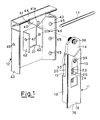
- the mounting device according to the invention is indicated overall by 10 (Figure 3), and is structurally formed by combining a coupling module 11 with a plate 12, which can be of different configurations as explained hereinafter.
- a single pin 13 articulatedly connects the module 11 to the plate 12 ( Figure 1).
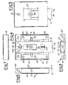
- the module 11 is composed of a core 14 which is partly surrounded by an outer box casing 15 which by a projecting end 16 defines the actual coupling element of the device.
- the core 14 and casing 15 are interconnected telescopically and together define a body of generally parallelepiped extending form. More specifically, the core 14 comprises profiled longitudinal side sections 17 ( Figure 2) contained within complementary guides 18 in the casing 15, which taper as at 19. Said tapered portions 19 comprise a cut-out 20 defining end stops 21, 22, the purpose of which is explained hereinafter.
- the core 14 and casing 15 can be moved relative to each other by a first kinematic mechanism comprising a screw 23 which is screwed through aligned holes 24 and 25 provided in respective lugs 26 and 27 punched integrally out of the box casing 15.
- the shank of the screw 23 extends through a passageway 28 in the core 14, whereas its head 29 sits within a housing 30 which is appropriately shaped to also receive two opposing pinions 31 which are engaged at 90° with a toothing 32 provided on said head 29 of the screw 23.
- a shaped plug 33 correspondingly closes the housing 30 to keep the head 39 and pinions 31 securely in position.
- Said plug 33 also comprises a through hole 34 aligned with the through holes 35 of the core 14, to receive the pin 13 for articulatedly connecting the coupling module 11 to the plate 12, said pin 13 also passing through said cut-outs 20.
- the mechanism 31, 32, 23, 26 and 25 ( Figures 1 and 2) can be operated by one or other of two screw heads 36, which are integral with the respective pinions 31 and are accessible from the interior of the furniture item through a large aperture 37 in the plate 13 ( Figures 2 and 5) and from the outside through an aperture 33a in the plug 33.
- a screw 123 with a slot 123a at its free end for a screwdriver can be provided ( Figure 2) to be able to slide the core and 14 and casing 15 relative to each other from the outside of the furniture item.
- the head 129 of the screw 123 will be free of toothing.
- the coupling module 11 is completed by a screw 38 (forming the second adjustment kinematic mechanism) with heads for operation by screwdrivers at both ends, and which is screwed through a hole 39 at the upper end of the core 14.
- said screw 38 cooperates with an abutment 40 on the plate 12, behind which the upper end of the core 14 is wedged.
- the screw 38 can be operated either from the interior of the furniture item via a hole 41 in the plate 12 ( Figures 2 and 5) or from the outside via a hole 41a in the abutment 40.
- the plate 12 ( Figures 1-8) comprises a central pair of opposing fins 42 for containing and guiding the coupling module 11, ad is made into box form on the sides 43 and top 44 by bending the sheet metal inwards to define triangular sections which not only stiffen the system but also allow the device to be fixed to the furniture item as shown in Figures 11 and 12.
- said triangular sections 43 and 44 comprise a series of aligned holes 45 for the guided passage of fixing screws 75 ( Figure 11).
- sections 43 are provided with holes 46 aligned with the holes 47 in the fins 42, for passage of the pin 13.
- Said abutment 40 which collaborates with the screw 38 extends from the section 44.
- the device assembled as shown in Figure 3 is fixed by screwing the plate 12 to the side 48 and preferable also to the upper wall 49 (top) of an item of wall furniture, to the rear of the back panel 50 ( Figure 11).
- At least two of such devices are provided per furniture item, one on each side, so that it can be hung onto the wall by engaging the coupling end 16 with a shaped bar 51 fixed to the wall (not shown), or with other equivalent elements such as hook plugs.
- the coupling end 16 is shaped with a cut-out 76 which ensures that the coupling element can be adjusted horizontally not only along a bar but also on a hook plug or the like.
- the back panel When the furniture item has been hooked to the wall in the described manner, its position relative to the wall can be comfortable adjusted by adjusting the screws 36 and 38 or the screw 123. If the adjustment is made from the interior of the furniture item, the back panel will comprise two apertures with a finishing plug as shown in Figure 12, whereas if the adjustment is made entirely from the exterior of the furniture item, the back panel will be without apertures, as shown in Figure 13.
- the furniture item By turning the screw 38 in one direction or the other the furniture item can be moved away from or towards the wall by the relative rotation of the module 11 and plate 12 about the pin 13. If the screw 36 or alternatively the screw 123 is turned, the height of the furniture item can be adjusted by the relative movement between 14 and 15.
- Access to the adjustment screws 36 and 38 from the exterior of the furniture item is via the apertures 33a and 41a provided in the plug 33 and in the abutment 40 respectively.
- the coupling module 11 can be mounted on plates 12 of different type, formed according to the structure of the furniture item to which they are to be fitted, or according to the system used to fix them to them to the furniture item (manual or mobile), or according to their fixing position.
- Figures 14-16 of the drawings show a non-limiting embodiment of plates 12 on which the coupling module 11 is mounted.
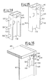
- Figures 14 and 15 are perspective views of a plate 112 (right and left) having a box structure with side walls 53 and an upper wall 54 which between them receive the coupling module 11, having the same structure as shown in Figures 1 to 12 of the drawings.
- the side walls 53 are provided with bored pegs 55 for fixing the plate 112 to the item of wall furniture, the abutment 40 being formed on the front and extending downwards to cooperate with the screw 38 for adjusting the coupling module 11, in the manner heretofore described.
- FIG 16 The system for fixing the plate 112 to the furniture item is shown in Figure 16, in which it can be clearly seen how the plate 112 can be fixed at the corner formed by the side 48 and top 49, by housing the bored pegs 55 in holes provided in the side 48 and then fixing them by screws 56.
- Figure 17 shows a further embodiment of the invention in which the coupling module 11 is associated with a plate 712 having a box structure equivalent to that of the aforesaid plates but with a lengthened side wall 70 which is to be fixed to the side wall 48 of the furniture item, possibly some distance from its top 49.
- the fixing of the device to the furniture item is made secure by the collaboration of a jaw 71 which is tightened against the back panel 50 by a pair of screws 72 provided on the coupling module 11 and passing through holes 73 in the plate 712 and oval holes 74 in the coupling module 11.
- Figure 18 shows the system for mounting the device described with reference to Figure 17, the device being fixed laterally to the side wall 48 of the furniture item and additionally tightened against the back panel 50, which is thus clamped between the jaw 71 and the plate 712.
- a cap is provided for the jaw 71, to complete the internal appearance of the furniture item.
Landscapes
- Furniture Connections (AREA)
- Connection Of Plates (AREA)
- Supports Or Holders For Household Use (AREA)
- Hinges (AREA)
- Cabinets, Racks, Or The Like Of Rigid Construction (AREA)
Claims (15)
- Verborgene Vorrichtung zur Wandmontage eines Wandmöbelelements, welche in Kombination aufweist: eine an dem Möbelelement zu befestigende Platte (12), ein Anschlußelement (11), das gelenkig mit der Platte (12) verbunden und derart angeordnet ist, daß es mit einem an der Wand befestigten Stützkörper (51) zusammenwirkt, und erste und zweite kinematische Einstelleinrichtungen, welche zwischen der Platte (12) und dem Anschlußelement (11) zum Einstellen sowohl der vertikalen Position des Anschlußelements (11) relativ zur Wand als auch eines zwischen der Platte (12) und dem Anschlußelement (11) ausgebildeten Winkels wirken, dadurch gekennzeichnet, daß das Anschlußelement einen Anschlußmodul (11) aufweist, der von der Platte (12) trennbar ist und die ersten und zweiten kinematischen Einstelleinrichtungen enthält, wobei der Anschlußmodul (11) aus einem Kern (14) besteht, der teilweise von einem äußeren mittels eines vorstehenden Endes (16) das wirksame Anschlußelement der Vorrichtung bildenden Kastengehäuse (15) umgeben ist, der Kern (14) und das Gehäuse (15), die teleskopartig miteinander verbunden sind, einen Körper von im allgemeinen einer Form eines Parallelepipeds bilden, die ersten und zweiten kinematischen Einstelleinrichtungen zwischen dem Kern (14) und Gehäuse (15) wirken welche Einstelleinrichtungen derart arbeiten, daß sie eine Relativbewegung jeweils zwischen dem Kern (14)) und dem Gehäuse (15) und eine Relativdrehung jeweils zwischen dem Anschlußmodul (11) und der Halteplatte (12) ermöglichen.
- Vorrichtung nach Anspruch 1, dadurch gekennzeichnet, daß der Anschlußmodul (11) in bezug auf die Platte (12) mittels eines Querstiftes (13) schwenkbar ist, welcher sich durch die Platte und den Anschlußmodul erstreckt.
- Vorrichtung nach Anspruch 1, dadurch gekennzeichnet, daß das Gehäuse (15) seitliche Führungen (18) aufweist, in denen Ausschnitte (20) vorgesehen sind, die mit dem Stift (13) zusammenwirkende Anschläge (21, 22) aufweisen.
- Vorrichtung nach Anspruch 1, dadurch gekennzeichnet, daß die erste kinematische Einstelleinrichtung eine Schraube (23), die in das Kastenelement (15) eingeschraubt ist; und wenigstens ein mit einer am Kopf (29) der Schraube (23) vorgesehenen Verzahnung (32) in Eine stehendes Zahnrad (31) aufweist, wobei der Kopf (29) und das Zahnrad (31) in einem Gehäuse (30) angeordnet sind, welches durch eine den Kopf (29) und das Zahnrad (31) sicher in ihrer Stellung haltende Formkappe (33) abgedeckt ist.
- Vorrichtung nach Anspruch 1, dadurch gekennzeichnet, daß die zweite kinematische Einstelleinrichtung eine Schraube (38) aufweist, die in eine am oberen Ende des Kerns (14) vorgesehene Bohrung (39) eingeschraubt ist und mit einem an der Platte (12) vorgesehenen Gegenlager (40) zusammenwirkt, hinter welchem das obere Ende des Kerns (14) festgeklemmt ist.
- Vorrichtung nach Anspruch 1, dadurch gekennzeichnet, daß die Platte (12) zum Aufnehmen des Anschlußmodul (11) im allgemeinen kastenförmig ausgebildet ist und zu ihrer Befestigung an dem Wandmöbelelement eine Befestigungseinrichtung aufweist.
- Vorrichtung nach Anspruch 6, dadurch gekennzeichnet, daß die Befestigungseinrichtung einen Flansch aufweist.
- Vorrichtung nach Anspruch 6, dadurch gekennzeichnet, daß die Befestigungseinrichtung mit Zapfen versehene Flanschen aufweist.
- Vorrichtung nach Anspruch 6, dadurch gekennzeichnet, daß die Befestigungseinrichtung Paare von Formansätzen aufweist.
- Vorrichtung nach Anspruch 1, dadurch gekennzeichnet, daß die Platte (12) ein zentrales Paar von gegenüberliegenden Stegen (42) zum Aufnehmen und Führen des Aschlußmoduls (11) aufweist und an ihren Seiten (43) sowie an ihrer Oberseite (44) durch Abbiegen des Metallblechs nach innen kastenförmig ausgebildet ist und dadurch dreiseitige Abschnitte zum Versteifen der Konstruktion und zum Befestigen der Platte an dem Möbelelement mit Hilfe von Schrauben bildet, die sich durch miteinander fluchtende Bohrungen (45) in den dreiseitigen Abschnitten (43, 44,) hindurcherstrecken.
- Vorrichtung nach Anspruch 1, dadurch gekennzeichnet, daß die ersten und zweiten kinematischen Einrichtungen sowohl von der Innenseite als auch von der Außenseite des Möbelelements her zugänglich sind.
- Vorrichtung nach Anspruch 11, dadurch gekennzeichnet, daß der Anschlußmodul (11) einen Kern (14) aufweist, der von einem äußeren Kastengehäuse (15) teilweise umgeben ist, dessen vorstehendes Ende (16) das wirksame Anschlußelement der Vorrichtung bildet, wobei der Kern (14) und das Gehäuse (15) zum Festlegen eines Körpers im allgemeinen in Form eines Parallelepipeds teleskopartig miteinander verbunden sind, erste und zweite kinematische Einstelleinrichtungen zwischen dem Kern (14) und dem Gehäuse (15) wirken, die derart arbeiten, daß sie eine Relativbewegung jeweils zwischen dem Kern (14) und dem Gehäuse (15) und eine Relativdrehung jeweils zwischen dem Anschlußmodul (11) und der Befestigungsplatte (12) ermöglichen, und wobei die erste kinematischen Einstelleinrichtungen eine Schraube (23), die in das kastenförmige Element (15) eingeschraubt ist, sowie zwei Zahnräder (31) aufweist, die mit einer am Kopf (29) der Schraube (23) vorgesehenen Verzahnung (32) kämmen und Köpfe (36) zum Aufnehmen eines Schraubendrehers haben.
- Vorrichtung nach Anspruch 12, dadurch gekennzeichnet, daß der Kopf (29) und die Zahnräder (31) innerhalb eines durch eine Formkappe (33) abgedeckten Gehäuses (30) angeordnet sind, welche Formkappe den Kopf (29) und die Zahnräder (31) sicher in ihren Positionen hält.
- Vorrichtung nach Anspruch 13, dadurch gekennzeichnet, daß die zweite kinematischen Einstelleinrichtung eine Schraube (38) aufweist, die in eine am oberen Ende des Kerns (14) vorgesehene Bohrung (39) eingeschraubt ist und mit einem an der Platte (12) vorgesehenen Gegenlager (40) zusammenwirkt, hinter welchem das obere Ende des Kerns (14) festgeklemmt ist, wobei die Schraube (38) an ihren beiden Enden Einstellschlitze für einen Schraubendreher aufweist und über eine Bohrung (41) in der Platte (12) vom Innenraum des Möbelelements und über eine Bohrung (41a) in dem Gegenlager (40) von der Außenseite des Möbelelements her zugänglich ist.
- Vorrichtung nach Anspruch 11, dadurch gekennzeichnet, daß die erste kinematische Einstelleinrichtung eine Schraube (123) aufweist, welche in das Kastengehäuse (15) eingeschraubt ist und an ihrem freien Ende einen Schlitz (123a) für einen Schraubendreher aufweist.
Applications Claiming Priority (4)
| Application Number | Priority Date | Filing Date | Title |
|---|---|---|---|
| IT8919823A IT1228679B (it) | 1989-03-20 | 1989-03-20 | Dispositivo nascosto per il montaggio a parete di un mobile pensile. |
| IT1982389 | 1989-03-20 | ||
| IT02250189A IT1237839B (it) | 1989-11-24 | 1989-11-24 | Dispositivo nascosto perfezionato per il montaggio a parete di un mobile pensile |
| IT2250189 | 1989-11-24 |
Publications (3)
| Publication Number | Publication Date |
|---|---|
| EP0389054A2 EP0389054A2 (de) | 1990-09-26 |
| EP0389054A3 EP0389054A3 (de) | 1991-12-18 |
| EP0389054B1 true EP0389054B1 (de) | 1995-07-05 |
Family
ID=26327320
Family Applications (1)
| Application Number | Title | Priority Date | Filing Date |
|---|---|---|---|
| EP90200644A Expired - Lifetime EP0389054B1 (de) | 1989-03-20 | 1990-03-19 | Verborgene Vorrichtung zur Wandmontage eines Wandmöbelelementes |
Country Status (5)
| Country | Link |
|---|---|
| US (1) | US5090652A (de) |
| EP (1) | EP0389054B1 (de) |
| AT (1) | ATE124608T1 (de) |
| DE (1) | DE69020604T2 (de) |
| ES (1) | ES2074523T3 (de) |
Families Citing this family (21)
| Publication number | Priority date | Publication date | Assignee | Title |
|---|---|---|---|---|
| DE3931370A1 (de) * | 1989-09-20 | 1991-03-28 | Miele & Cie | Mehrdimensional verstellbarer beschlag fuer haengeschraenke oder -regale |
| IT1240042B (it) * | 1990-05-04 | 1993-11-27 | Lema Spa | Dispositivo di supporto a scomparsa per fissare un ripiano ad un muro |
| DE69303186T2 (de) | 1992-02-14 | 1996-11-21 | Camar Spa | Verbesserte verborgene Vorrichtung zur Wandmontage eines Wandmöbelelementes |
| US5624168A (en) * | 1994-08-24 | 1997-04-29 | Licciardello, Sr.; Morris F. | Cabinet mounting apparatus |
| US5570865A (en) * | 1994-09-16 | 1996-11-05 | Godfrey; Kenneth E. | Article restraint and fall prevention device |
| IT249750Y1 (it) * | 2000-01-28 | 2003-05-28 | Leonardo Srl | Dispositivo nascosto per il montaggio a parete di un mobile pensile |
| ITMI20070789A1 (it) * | 2007-04-18 | 2008-10-19 | Leonardo Srl | Gruppo reggipensile nascosto e regolabile per il montaggio a parete di un mobile pensile |
| DE202007006527U1 (de) * | 2007-05-04 | 2008-09-18 | Hettich-Heinze Gmbh & Co. Kg | Verbindungsanordnung |
| IT1390845B1 (it) * | 2008-07-29 | 2011-10-19 | Leonardo Srl | Gruppo reggipensile regolabile per l'ancoraggio a parete di un mobile pensile |
| IT1392187B1 (it) * | 2008-12-12 | 2012-02-22 | Leonardo Srl | Dispositivo di regolazione verticale per il montaggio a parete di pannelli di rivestimento |
| ES2356652B1 (es) * | 2009-06-23 | 2012-02-10 | Miguel Angel Rioja Calvo | Dispositivo de anclaje basculante mural para muebles. |
| ES2384956B1 (es) * | 2010-04-15 | 2013-05-20 | Miguel Ángel Rioja Calvo | Soporte inferior nivelador de muebles en pared. |
| ES2395814B1 (es) * | 2011-06-30 | 2013-07-15 | Miguel Angel Rioja Calvo | Soporte inferior para muebles en pared |
| US8979054B2 (en) * | 2012-12-17 | 2015-03-17 | 3M Innovative Properties Company | Wall mountable storage assembly with articulating connection |
| ES2716405T3 (es) * | 2014-05-14 | 2019-06-12 | Leonardo Srl | Sistema de pared de paneles de revestimiento y soportes colgantes con un dispositivo de regulación vertical |
| TWI592117B (zh) * | 2014-06-06 | 2017-07-21 | Kuangyi Chen | Cabinets with concealed wall holes side panel structure |
| IT201600070928A1 (it) * | 2016-07-07 | 2018-01-07 | Leonardo Srl | Giunzione compatta per collegare un primo pannello e un secondo pannello di mobili e di altri articoli di arredamento |
| IT201600103544A1 (it) * | 2016-10-14 | 2018-04-14 | Leonardo Srl | Gruppo reggipensile nascosto con antisganciamento ad accesso facilitato alle regolazioni |
| IT201700110599A1 (it) * | 2017-10-03 | 2019-04-03 | Leonardo Srl | Gruppo reggipensile nascosto resistente allo strappo e con regolazione in profondita’ precisa |
| CA3113093A1 (en) * | 2018-10-26 | 2020-04-30 | Leonardo S.R.L. | Improved actuation and blocking system of a joint between a shoulder and a shelf of a piece of furniture or other furnishing items |
| IT201900022788A1 (it) * | 2019-12-03 | 2021-06-03 | Ferramenta Livenza Soc A Responsabilita Limitata | Dispositivo di supporto angolare per mobili pensili |
Family Cites Families (9)
| Publication number | Priority date | Publication date | Assignee | Title |
|---|---|---|---|---|
| DE1429557A1 (de) * | 1963-05-29 | 1968-12-12 | Heinze Fa R | Aufhaengevorrichtung,insbesondere fuer Wandschraenke |
| DE2435842A1 (de) * | 1974-07-25 | 1976-02-12 | E Norm Beschlag Gmbh | Verstellbare aufhaengevorrichtung fuer an einer wand festlegbare moebelstuecke |
| AT352338B (de) * | 1976-05-13 | 1979-09-10 | Blum Gmbh Julius | Verstellbare aufhaengevorrichtung fuer haenge- schraenke od.dgl. |
| DE2717169C2 (de) * | 1977-04-19 | 1982-10-07 | Hetal-Werke Franz Hettich Gmbh & Co, 7297 Alpirsbach | Verstellbare Aufhängevorrichtung für ein an einer Wand befestigbares Möbelstück |
| US4220809A (en) * | 1979-01-02 | 1980-09-02 | Burroughs Corporation | Protective mechanism for electronic apparatus |
| AT375535B (de) * | 1979-11-19 | 1984-08-10 | Blum Gmbh Julius | Aufhaengebeschlag fuer moebel |
| DE3111357A1 (de) * | 1981-03-23 | 1983-02-03 | Hetal-Werke Franz Hettich Gmbh & Co, 7297 Alpirsbach | Verstellbarer aufhaengebeschlag |
| IT206608Z2 (it) * | 1986-05-22 | 1987-08-10 | Camar Spa | Disposizione di montaggio per mobili. |
| IT1218247B (it) * | 1988-05-20 | 1990-04-12 | Camar Spa | Sistema perfezionamento per il montaggio a parete di un mobile a sbalzo |
-
1990
- 1990-03-19 ES ES90200644T patent/ES2074523T3/es not_active Expired - Lifetime
- 1990-03-19 EP EP90200644A patent/EP0389054B1/de not_active Expired - Lifetime
- 1990-03-19 DE DE69020604T patent/DE69020604T2/de not_active Expired - Fee Related
- 1990-03-19 AT AT90200644T patent/ATE124608T1/de not_active IP Right Cessation
- 1990-03-19 US US07/495,841 patent/US5090652A/en not_active Expired - Fee Related
Also Published As
| Publication number | Publication date |
|---|---|
| DE69020604D1 (de) | 1995-08-10 |
| ES2074523T3 (es) | 1995-09-16 |
| US5090652A (en) | 1992-02-25 |
| EP0389054A2 (de) | 1990-09-26 |
| DE69020604T2 (de) | 1996-02-08 |
| ATE124608T1 (de) | 1995-07-15 |
| EP0389054A3 (de) | 1991-12-18 |
Similar Documents
| Publication | Publication Date | Title |
|---|---|---|
| EP0389054B1 (de) | Verborgene Vorrichtung zur Wandmontage eines Wandmöbelelementes | |
| EP0707815A2 (de) | Verbesserte, verborgene Vorrichtung zur Wandmontage eines Wandmöbelelementes | |
| US5664857A (en) | Metal fitting holder for front faces of drawers | |
| US5316373A (en) | Seat arm rest | |
| US5333950A (en) | Control cabinet with rack and mounting plate | |
| US5368380A (en) | Cabinet assembly | |
| US4497148A (en) | Panel connector system | |
| US4744126A (en) | Combined pull and carry handle | |
| US6145897A (en) | Push-bar for doors in general | |
| RU2756221C2 (ru) | Потайной навесной кронштейн в сборе с противорасцепляющим механизмом, обеспечивающий легкий доступ к средствам регулировки | |
| US20080156514A1 (en) | Adjustable Electrical Box Assembly | |
| CA2215774A1 (en) | Device for attaching the front panel of a drawer to the side walls of a drawer | |
| US6726296B2 (en) | Cabinet and undersink drawers | |
| JP2008507413A (ja) | モジュール式保管庫組立て品 | |
| EP0624733A2 (de) | Vorrichtung zum Befestigen und Seitenjustieren der Frontverkleidung einer Schublade | |
| EP1279080A1 (de) | Scharnierkappe für ein scharnierblatt | |
| US4579400A (en) | Locker construction | |
| US8002366B2 (en) | Drawer | |
| EP2510834B1 (de) | Versteckte Vorrichtung für die Wandanordnung einer strukturellen Komponente eins Möbelstücks mit Seitenregulierung | |
| EP2789780B1 (de) | Trag- und Stelleinrichtung eines Wagens für Schiebetüren | |
| EP1161898B1 (de) | Vorrichtung zur schnellen Befestigung einer hölzernen Frontblende an Schubladenzargen | |
| EP0418769B1 (de) | Mehrdimensional verstellbarer Beschlag für Hängeschränke oder -regale | |
| KR200496411Y1 (ko) | 가구용 손잡이 | |
| KR20040082097A (ko) | 빌트인 저장고의 도어조립체 | |
| US5052847A (en) | Fixing plate for concealed devices used for wall-mounting an item of wall furniture |
Legal Events
| Date | Code | Title | Description |
|---|---|---|---|
| PUAI | Public reference made under article 153(3) epc to a published international application that has entered the european phase |
Free format text: ORIGINAL CODE: 0009012 |
|
| AK | Designated contracting states |
Kind code of ref document: A2 Designated state(s): AT BE CH DE DK ES FR GB GR IT LI LU NL SE |
|
| PUAL | Search report despatched |
Free format text: ORIGINAL CODE: 0009013 |
|
| AK | Designated contracting states |
Kind code of ref document: A3 Designated state(s): AT BE CH DE DK ES FR GB GR IT LI LU NL SE |
|
| 17P | Request for examination filed |
Effective date: 19920319 |
|
| 17Q | First examination report despatched |
Effective date: 19930513 |
|
| GRAA | (expected) grant |
Free format text: ORIGINAL CODE: 0009210 |
|
| ITF | It: translation for a ep patent filed | ||
| AK | Designated contracting states |
Kind code of ref document: B1 Designated state(s): AT BE CH DE DK ES FR GB GR IT LI LU NL SE |
|
| PG25 | Lapsed in a contracting state [announced via postgrant information from national office to epo] |
Ref country code: NL Free format text: LAPSE BECAUSE OF FAILURE TO SUBMIT A TRANSLATION OF THE DESCRIPTION OR TO PAY THE FEE WITHIN THE PRESCRIBED TIME-LIMIT Effective date: 19950705 Ref country code: LI Effective date: 19950705 Ref country code: GR Free format text: LAPSE BECAUSE OF FAILURE TO SUBMIT A TRANSLATION OF THE DESCRIPTION OR TO PAY THE FEE WITHIN THE PRESCRIBED TIME-LIMIT Effective date: 19950705 Ref country code: FR Effective date: 19950705 Ref country code: DK Effective date: 19950705 Ref country code: CH Effective date: 19950705 Ref country code: BE Effective date: 19950705 Ref country code: AT Effective date: 19950705 |
|
| REF | Corresponds to: |
Ref document number: 124608 Country of ref document: AT Date of ref document: 19950715 Kind code of ref document: T |
|
| REF | Corresponds to: |
Ref document number: 69020604 Country of ref document: DE Date of ref document: 19950810 |
|
| REG | Reference to a national code |
Ref country code: ES Ref legal event code: FG2A Ref document number: 2074523 Country of ref document: ES Kind code of ref document: T3 |
|
| PG25 | Lapsed in a contracting state [announced via postgrant information from national office to epo] |
Ref country code: SE Effective date: 19951005 |
|
| REG | Reference to a national code |
Ref country code: CH Ref legal event code: PL |
|
| EN | Fr: translation not filed | ||
| NLV1 | Nl: lapsed or annulled due to failure to fulfill the requirements of art. 29p and 29m of the patents act | ||
| PG25 | Lapsed in a contracting state [announced via postgrant information from national office to epo] |
Ref country code: LU Free format text: LAPSE BECAUSE OF NON-PAYMENT OF DUE FEES Effective date: 19960331 |
|
| PLBE | No opposition filed within time limit |
Free format text: ORIGINAL CODE: 0009261 |
|
| STAA | Information on the status of an ep patent application or granted ep patent |
Free format text: STATUS: NO OPPOSITION FILED WITHIN TIME LIMIT |
|
| 26N | No opposition filed | ||
| PGFP | Annual fee paid to national office [announced via postgrant information from national office to epo] |
Ref country code: DE Payment date: 19991231 Year of fee payment: 11 |
|
| PGFP | Annual fee paid to national office [announced via postgrant information from national office to epo] |
Ref country code: GB Payment date: 20000315 Year of fee payment: 11 |
|
| PGFP | Annual fee paid to national office [announced via postgrant information from national office to epo] |
Ref country code: ES Payment date: 20000322 Year of fee payment: 11 |
|
| PG25 | Lapsed in a contracting state [announced via postgrant information from national office to epo] |
Ref country code: GB Free format text: LAPSE BECAUSE OF NON-PAYMENT OF DUE FEES Effective date: 20010319 |
|
| PG25 | Lapsed in a contracting state [announced via postgrant information from national office to epo] |
Ref country code: ES Free format text: LAPSE BECAUSE OF NON-PAYMENT OF DUE FEES Effective date: 20010320 |
|
| GBPC | Gb: european patent ceased through non-payment of renewal fee |
Effective date: 20010319 |
|
| PG25 | Lapsed in a contracting state [announced via postgrant information from national office to epo] |
Ref country code: DE Free format text: LAPSE BECAUSE OF NON-PAYMENT OF DUE FEES Effective date: 20020101 |
|
| REG | Reference to a national code |
Ref country code: ES Ref legal event code: FD2A Effective date: 20030203 |
|
| PG25 | Lapsed in a contracting state [announced via postgrant information from national office to epo] |
Ref country code: IT Free format text: LAPSE BECAUSE OF NON-PAYMENT OF DUE FEES;WARNING: LAPSES OF ITALIAN PATENTS WITH EFFECTIVE DATE BEFORE 2007 MAY HAVE OCCURRED AT ANY TIME BEFORE 2007. THE CORRECT EFFECTIVE DATE MAY BE DIFFERENT FROM THE ONE RECORDED. Effective date: 20050319 |