EP0389851A2 - Dispositif de roulement pour aiguille d'aiguillage - Google Patents
Dispositif de roulement pour aiguille d'aiguillage Download PDFInfo
- Publication number
- EP0389851A2 EP0389851A2 EP90104552A EP90104552A EP0389851A2 EP 0389851 A2 EP0389851 A2 EP 0389851A2 EP 90104552 A EP90104552 A EP 90104552A EP 90104552 A EP90104552 A EP 90104552A EP 0389851 A2 EP0389851 A2 EP 0389851A2
- Authority
- EP
- European Patent Office
- Prior art keywords
- tongue
- switch tongue
- arm
- switch
- support
- Prior art date
- Legal status (The legal status is an assumption and is not a legal conclusion. Google has not performed a legal analysis and makes no representation as to the accuracy of the status listed.)
- Withdrawn
Links
Images


Classifications
-
- E—FIXED CONSTRUCTIONS
- E01—CONSTRUCTION OF ROADS, RAILWAYS, OR BRIDGES
- E01B—PERMANENT WAY; PERMANENT-WAY TOOLS; MACHINES FOR MAKING RAILWAYS OF ALL KINDS
- E01B7/00—Switches; Crossings
- E01B7/02—Tongues; Associated constructions
-
- E—FIXED CONSTRUCTIONS
- E01—CONSTRUCTION OF ROADS, RAILWAYS, OR BRIDGES
- E01B—PERMANENT WAY; PERMANENT-WAY TOOLS; MACHINES FOR MAKING RAILWAYS OF ALL KINDS
- E01B2202/00—Characteristics of moving parts of rail systems, e.g. switches, special frogs, tongues
- E01B2202/02—Nature of the movement
- E01B2202/027—Including a component perpendicular to the plane of the rails
-
- E—FIXED CONSTRUCTIONS
- E01—CONSTRUCTION OF ROADS, RAILWAYS, OR BRIDGES
- E01B—PERMANENT WAY; PERMANENT-WAY TOOLS; MACHINES FOR MAKING RAILWAYS OF ALL KINDS
- E01B2202/00—Characteristics of moving parts of rail systems, e.g. switches, special frogs, tongues
- E01B2202/04—Nature of the support or bearing
- E01B2202/042—Sliding
-
- E—FIXED CONSTRUCTIONS
- E01—CONSTRUCTION OF ROADS, RAILWAYS, OR BRIDGES
- E01B—PERMANENT WAY; PERMANENT-WAY TOOLS; MACHINES FOR MAKING RAILWAYS OF ALL KINDS
- E01B2202/00—Characteristics of moving parts of rail systems, e.g. switches, special frogs, tongues
- E01B2202/04—Nature of the support or bearing
- E01B2202/044—Rolling
- E01B2202/046—Rolling with rolls on fixed part
Definitions
- the invention relates to a switch tongue rolling device, in particular the transport part of said rolling device, which is also lubrication-friendly or even lubrication-free and almost completely eliminates the lubrication of sliding chairs.
- the switch tongue must be lubricated, or extreme steering or steering force may then be required in the edge position.
- the switch tongue In some depictions in the font DD - 65901 there is also a movement of the switches tongue perceptible in the entire path of the rolling bearing, this version is not explained in the description.
- the bearing on a rolling element which is also load-bearing when fully loaded, would cause permanent deformations of the seat surfaces during a train passage.
- bearings of the switch tongues on flexibly suspended rollers are known. Such a suspension or suspension fulfills the requirement of rolling bearings with low friction and with minimal lubrication, in which the total load is on the sliding chairs.
- Some known solutions also have a variable lifting force of the switch tongue, for example DD - 56536, 61558, 66638 etc. In these cases, however, the change in lifting force appears to be constant and relatively slight. Also in the description of said patents one does not speak of a special meaning of the force required for lifting / levitation / or of a progressive change of this force during the advancing movement of the switch tongue. Here, too, a feed in a raised position and the lying on the ground are only accepted when the train passes through. Here too, the device has the disadvantage of an alternating resting of the switch tongue.
- Said device consists of a holder of the same, which is fastened to the underside of the tongue support by means of hooks and clamps with a screw, furthermore an arm of the rolling device, connected by bolts to the aforementioned holder, the device arm being located on the opposite side of the tongue support without connecting bolts and is connected by means of spring bolts to the spring screw which rests on a spring supported on the holder of the rolling device.
- the rolling or sliding element has at least two abutment points located between the arm pin and the tongue support, the first abutment point closer to the arm pin dividing the distance between the arm pin and the other abutment point in a ratio of 40:60 to 80:20; when the switch tongue rests on the tongue support, the switch tongue lies only on the other abutment point and the tongue base is at most 5 mm away from the first abutment point.
- the bumps are preferably roller bearings, but can also be provided in a sliding, self-lubricating version.
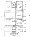
- Figure 1 shows a vertical cross-section through a device with roller bearings
- Figure 2 shows a vertical cross-section through a variant with self-lubricating layer
- Figure 3 shows a plan of the form with roller bearings.
- Figure 1 shows the attachment of the device holder 3 to the tongue support 1 by means of the hook 15 and the clamp 5 with screw 6 .
- the arm of the device 4 is connected by means of arm bolts 10 and at the same time the block with roller bearings, formed by bearings 12 on bolts 11 , and the switch tongue 2 carried by bearings 12 are connected.
- the arm of the rolling device 4 is connected on the other side by the spring bolt 9 to the spring screw 8 and this is supported by a washer on the spring 7 resting on the arm of the rolling device 4 .
- a slide support 13 is connected to the arm of the device 4 , the abutment points 16 and 17 of which are supported in turn on a housing with a hard, self-lubricating surface 14 , which is fastened in the foot of the switch tongue 18 .
- Figure 3 shows the arrangement of the device arm 4 in the device holder 3 with arm bolts 10 and rollers 12 on bolts 11 .
- the device works as follows: by hand or by means of a servo motor, the switch tongue is switched from free to the working position via the preferably roller bearing.
- the base of the switch tongue rolls over the first or both joints and at the end of the feed, it is only supported via the second joint. This progressively increases the moment of the loading force acting on the device arm; this is lowered with a suitable spring setting, and the switch tongue lies lightly on the sliding chairs, if necessary, it is pushed a little towards the tongue support and locked by the feed mechanism.
- the other switch tongue moves in exactly the opposite order.
- a plain instead of roller bearing is suitable, for example, for hot operations where the internal lubrication of the bearings could fail.
- the device described according to the invention is used for all types of switch tongues and for all track gauges. It can advantageously be installed as an additional device in existing switch blades. With their arrangement, they do not hinder the original design and can be connected in a very short time and without removing the other components of the switch tongue. In the case of long switch blades, several rolling devices can be used in series. The switch tongue rolling device was during heavy operation u. Tested at low speeds and proven to be reliable.
Landscapes
- Engineering & Computer Science (AREA)
- Mechanical Engineering (AREA)
- Architecture (AREA)
- Civil Engineering (AREA)
- Structural Engineering (AREA)
- Railway Tracks (AREA)
Applications Claiming Priority (2)
| Application Number | Priority Date | Filing Date | Title |
|---|---|---|---|
| CS891966A CZ196689A3 (en) | 1989-03-30 | 1989-03-30 | Rail point slide |
| CS1966/89 | 1989-03-30 |
Publications (2)
| Publication Number | Publication Date |
|---|---|
| EP0389851A2 true EP0389851A2 (fr) | 1990-10-03 |
| EP0389851A3 EP0389851A3 (fr) | 1991-06-12 |
Family
ID=5355399
Family Applications (1)
| Application Number | Title | Priority Date | Filing Date |
|---|---|---|---|
| EP19900104552 Withdrawn EP0389851A3 (fr) | 1989-03-30 | 1990-03-09 | Dispositif de roulement pour aiguille d'aiguillage |
Country Status (3)
| Country | Link |
|---|---|
| EP (1) | EP0389851A3 (fr) |
| CZ (2) | CZ955U1 (fr) |
| SE (1) | SE9000720L (fr) |
Cited By (11)
| Publication number | Priority date | Publication date | Assignee | Title |
|---|---|---|---|---|
| DE4041264A1 (de) * | 1990-12-21 | 1992-06-25 | Peddinghaus Carl Dan Gmbh | Vorrichtung zum anheben der zungenschiene einer weiche |
| DE4224158A1 (de) * | 1992-07-22 | 1994-01-27 | Butzbacher Weichenbau Gmbh | Rolleneinrichtung |
| WO1994028246A1 (fr) * | 1993-05-25 | 1994-12-08 | Eco Production Vresová, Spol S.R.O | Dispositif de roulement de lames d'aiguilles |
| US5390881A (en) * | 1992-07-22 | 1995-02-21 | Bwg Butzbacher Weichenbau Gmbh | Roller assembly for a switch tongue used with a stock rail |
| WO1995022657A1 (fr) * | 1994-02-17 | 1995-08-24 | Bwg Butzbacher Weichenbau Gmbh | Dispositif a galets |
| US5482231A (en) * | 1994-06-07 | 1996-01-09 | Double T Railroad Products | Rail switch point assist apparatus |
| DE4424392A1 (de) * | 1994-07-13 | 1996-01-18 | Schreck Mieves Gmbh | Zungenhebevorrichtung |
| US5499786A (en) * | 1992-10-16 | 1996-03-19 | Voest-Alpine Eisenbahnsysteme Aktiengesellschaft | Device for facilitating the re-positioning of moveable rails or rail components |
| DE19515427A1 (de) * | 1995-04-26 | 1996-10-31 | Butzbacher Weichenbau Gmbh | Vorrichtung zur Lagefixierung eines zu einem ersten Schienenabschnitt verstellbaren zweiten Schienenabschnitts |
| AT412350B (de) * | 2002-04-23 | 2005-01-25 | Vae Eisenbahnsysteme Gmbh | Rolleinrichtung für eine bewegliche herzstückspitze |
| US12359377B1 (en) | 2024-04-10 | 2025-07-15 | voestalpine Railway Systems Nortrak LLC | Switch point roller assembly |
Family Cites Families (2)
| Publication number | Priority date | Publication date | Assignee | Title |
|---|---|---|---|---|
| DE1056641B (de) * | 1957-02-25 | 1959-05-06 | Carl Dan Peddinghaus Kommandit | Federnde, in der Hoehe einstellbare Rollenlagerung fuer Weichenzungen |
| LU75283A1 (fr) * | 1976-07-01 | 1978-02-08 |
-
1989
- 1989-03-30 CZ CZ1993985U patent/CZ955U1/cs unknown
- 1989-03-30 CZ CS891966A patent/CZ196689A3/cs unknown
-
1990
- 1990-02-28 SE SE9000720A patent/SE9000720L/ not_active Application Discontinuation
- 1990-03-09 EP EP19900104552 patent/EP0389851A3/fr not_active Withdrawn
Cited By (15)
| Publication number | Priority date | Publication date | Assignee | Title |
|---|---|---|---|---|
| EP0495160A1 (fr) * | 1990-12-21 | 1992-07-22 | CARL DAN. PEDDINGHAUS GMBH & CO. KG | Dispositif pour soulever la lame d'une aiguille |
| DE4041264A1 (de) * | 1990-12-21 | 1992-06-25 | Peddinghaus Carl Dan Gmbh | Vorrichtung zum anheben der zungenschiene einer weiche |
| DE4224158A1 (de) * | 1992-07-22 | 1994-01-27 | Butzbacher Weichenbau Gmbh | Rolleneinrichtung |
| US5390881A (en) * | 1992-07-22 | 1995-02-21 | Bwg Butzbacher Weichenbau Gmbh | Roller assembly for a switch tongue used with a stock rail |
| US5499786A (en) * | 1992-10-16 | 1996-03-19 | Voest-Alpine Eisenbahnsysteme Aktiengesellschaft | Device for facilitating the re-positioning of moveable rails or rail components |
| WO1994028246A1 (fr) * | 1993-05-25 | 1994-12-08 | Eco Production Vresová, Spol S.R.O | Dispositif de roulement de lames d'aiguilles |
| US5628480A (en) * | 1993-05-25 | 1997-05-13 | Eco Production Vresova, SPOL. S.R.O. | Switch blade rolling device |
| WO1995022657A1 (fr) * | 1994-02-17 | 1995-08-24 | Bwg Butzbacher Weichenbau Gmbh | Dispositif a galets |
| US5482231A (en) * | 1994-06-07 | 1996-01-09 | Double T Railroad Products | Rail switch point assist apparatus |
| US5622340A (en) * | 1994-06-07 | 1997-04-22 | Double T Railroad Products | Rail switch point assist apparatus |
| DE4424392A1 (de) * | 1994-07-13 | 1996-01-18 | Schreck Mieves Gmbh | Zungenhebevorrichtung |
| DE19515427A1 (de) * | 1995-04-26 | 1996-10-31 | Butzbacher Weichenbau Gmbh | Vorrichtung zur Lagefixierung eines zu einem ersten Schienenabschnitt verstellbaren zweiten Schienenabschnitts |
| AT412350B (de) * | 2002-04-23 | 2005-01-25 | Vae Eisenbahnsysteme Gmbh | Rolleinrichtung für eine bewegliche herzstückspitze |
| US7063293B2 (en) | 2002-04-23 | 2006-06-20 | Vae Eisenbahnsysteme Gmbh | Rolling device for a displaceable cross frog |
| US12359377B1 (en) | 2024-04-10 | 2025-07-15 | voestalpine Railway Systems Nortrak LLC | Switch point roller assembly |
Also Published As
| Publication number | Publication date |
|---|---|
| CZ196689A3 (en) | 1993-10-13 |
| EP0389851A3 (fr) | 1991-06-12 |
| SE9000720L (sv) | 1990-10-01 |
| CZ955U1 (cs) | 1993-11-05 |
| SE9000720D0 (sv) | 1990-02-28 |
Similar Documents
| Publication | Publication Date | Title |
|---|---|---|
| DE69206476T2 (de) | Vorrichtung zum Ausrichten und Befestigen von einem Schienenflansch. | |
| DE2729692C3 (de) | Vorrichtung zum Einbau in eine Bahngleisweiche | |
| DE69512205T2 (de) | Türkantenleitvorrichtung | |
| EP0389851A2 (fr) | Dispositif de roulement pour aiguille d'aiguillage | |
| EP0495160B1 (fr) | Dispositif pour soulever la lame d'une aiguille | |
| EP0700474A1 (fr) | Dispositif de roulement de lames d'aiguilles | |
| DE3904026A1 (de) | Gleiteinlage fuer geschlossene zungenvorrichtungen wie auch fuer gleitflaechen fuer bewegliche herzstueckspitzen, sowie verfahren zum befestigen einer derartigen gleiteinlage an dem gleitbett von rillenschienenzungenvorrichtungen | |
| CH644821A5 (de) | Rollenfuehrungsschuh fuer aufzuege. | |
| EP0156143B1 (fr) | Disposition de montage de dispositifs de frein à sabot pour véhicules sur rails | |
| DE3230612A1 (de) | Vorrichtung zum befestigen von backenschienen oder fahrschienen in weichen | |
| AT393850B (de) | Ueberbrueckungs-vorrichtung fuer dehnungsfugen in fahrbahnen von bruecken od. dgl. | |
| EP3955727B1 (fr) | Machine agricole | |
| DE10215280B4 (de) | Herzstückhebevorrichtung | |
| WO2018094434A1 (fr) | Dispositif pour monter une lame d'aiguille | |
| DE29701732U1 (de) | Scherenhubtisch | |
| EP0277291B1 (fr) | Attelage transversal entre deux bogies d'un véhicule sur rails | |
| EP0652996B1 (fr) | Dispositif a rouleau | |
| WO2026068315A1 (fr) | Cabine pour ascenseur | |
| CH626300A5 (fr) | ||
| EP4671081A1 (fr) | Dispositif de réglage d'aiguillage doté de propriétés de roulement améliorées | |
| DE19746587C1 (de) | Schienenlager mit Rollenlagern und Gleitlager zur Freihaltung der Schwelle von Kippmomenten | |
| AT519128A4 (de) | Vorrichtung zum bewegen einer zungenschiene einer weiche | |
| DE4020243C2 (fr) | ||
| AT20196B (de) | Selbsttätige Weichenstellvorrichtung. | |
| AT6156U1 (de) | Rollvorrichtung zum tragen von beweglichen weichenteilen |
Legal Events
| Date | Code | Title | Description |
|---|---|---|---|
| PUAI | Public reference made under article 153(3) epc to a published international application that has entered the european phase |
Free format text: ORIGINAL CODE: 0009012 |
|
| 17P | Request for examination filed |
Effective date: 19900621 |
|
| AK | Designated contracting states |
Kind code of ref document: A2 Designated state(s): AT DE FR |
|
| PUAL | Search report despatched |
Free format text: ORIGINAL CODE: 0009013 |
|
| AK | Designated contracting states |
Kind code of ref document: A3 Designated state(s): AT DE FR |
|
| 17Q | First examination report despatched |
Effective date: 19911129 |
|
| STAA | Information on the status of an ep patent application or granted ep patent |
Free format text: STATUS: THE APPLICATION HAS BEEN WITHDRAWN |
|
| 18W | Application withdrawn |
Withdrawal date: 19920224 |