EP0395685B1 - Method and apparatus for energy efficient drying - Google Patents
Method and apparatus for energy efficient drying Download PDFInfo
- Publication number
- EP0395685B1 EP0395685B1 EP88910089A EP88910089A EP0395685B1 EP 0395685 B1 EP0395685 B1 EP 0395685B1 EP 88910089 A EP88910089 A EP 88910089A EP 88910089 A EP88910089 A EP 88910089A EP 0395685 B1 EP0395685 B1 EP 0395685B1
- Authority
- EP
- European Patent Office
- Prior art keywords
- enclosure
- steam
- gas
- drying
- heat source
- Prior art date
- Legal status (The legal status is an assumption and is not a legal conclusion. Google has not performed a legal analysis and makes no representation as to the accuracy of the status listed.)
- Expired - Lifetime
Links
- 238000001035 drying Methods 0.000 title claims abstract description 64
- 238000000034 method Methods 0.000 title claims abstract description 31
- 239000000463 material Substances 0.000 claims abstract description 57
- 239000007789 gas Substances 0.000 claims description 52
- 230000003134 recirculating effect Effects 0.000 claims description 20
- 238000010438 heat treatment Methods 0.000 claims description 14
- 238000002485 combustion reaction Methods 0.000 claims description 8
- 239000012530 fluid Substances 0.000 claims description 8
- 238000013022 venting Methods 0.000 claims description 8
- 238000002347 injection Methods 0.000 claims description 6
- 239000007924 injection Substances 0.000 claims description 6
- 238000001816 cooling Methods 0.000 claims description 4
- 239000002826 coolant Substances 0.000 claims description 2
- 239000000112 cooling gas Substances 0.000 claims description 2
- 238000007865 diluting Methods 0.000 claims description 2
- XLYOFNOQVPJJNP-UHFFFAOYSA-N water Substances O XLYOFNOQVPJJNP-UHFFFAOYSA-N 0.000 abstract description 20
- 239000003570 air Substances 0.000 description 31
- 229910000831 Steel Inorganic materials 0.000 description 18
- 239000010959 steel Substances 0.000 description 18
- 238000001704 evaporation Methods 0.000 description 11
- 230000008020 evaporation Effects 0.000 description 11
- VNWKTOKETHGBQD-UHFFFAOYSA-N methane Chemical compound C VNWKTOKETHGBQD-UHFFFAOYSA-N 0.000 description 8
- IJGRMHOSHXDMSA-UHFFFAOYSA-N Atomic nitrogen Chemical compound N#N IJGRMHOSHXDMSA-UHFFFAOYSA-N 0.000 description 4
- 239000012080 ambient air Substances 0.000 description 4
- 239000003345 natural gas Substances 0.000 description 4
- 238000012546 transfer Methods 0.000 description 4
- 238000000605 extraction Methods 0.000 description 3
- 238000011084 recovery Methods 0.000 description 3
- 229910001220 stainless steel Inorganic materials 0.000 description 3
- 239000010935 stainless steel Substances 0.000 description 3
- CURLTUGMZLYLDI-UHFFFAOYSA-N Carbon dioxide Chemical compound O=C=O CURLTUGMZLYLDI-UHFFFAOYSA-N 0.000 description 2
- QVGXLLKOCUKJST-UHFFFAOYSA-N atomic oxygen Chemical compound [O] QVGXLLKOCUKJST-UHFFFAOYSA-N 0.000 description 2
- 238000005266 casting Methods 0.000 description 2
- 238000009833 condensation Methods 0.000 description 2
- 230000005494 condensation Effects 0.000 description 2
- 238000010276 construction Methods 0.000 description 2
- 229910052757 nitrogen Inorganic materials 0.000 description 2
- 239000001301 oxygen Substances 0.000 description 2
- 229910052760 oxygen Inorganic materials 0.000 description 2
- 230000009467 reduction Effects 0.000 description 2
- 238000007789 sealing Methods 0.000 description 2
- 238000005406 washing Methods 0.000 description 2
- 239000002699 waste material Substances 0.000 description 2
- 238000004804 winding Methods 0.000 description 2
- 230000001133 acceleration Effects 0.000 description 1
- 238000010923 batch production Methods 0.000 description 1
- 238000009835 boiling Methods 0.000 description 1
- 229910002092 carbon dioxide Inorganic materials 0.000 description 1
- 239000001569 carbon dioxide Substances 0.000 description 1
- 239000000567 combustion gas Substances 0.000 description 1
- 238000004891 communication Methods 0.000 description 1
- 238000010924 continuous production Methods 0.000 description 1
- 239000012153 distilled water Substances 0.000 description 1
- 230000000694 effects Effects 0.000 description 1
- 238000010304 firing Methods 0.000 description 1
- 239000006260 foam Substances 0.000 description 1
- 239000008246 gaseous mixture Substances 0.000 description 1
- 239000008236 heating water Substances 0.000 description 1
- 238000003780 insertion Methods 0.000 description 1
- 230000037431 insertion Effects 0.000 description 1
- 238000009413 insulation Methods 0.000 description 1
- ZFSLODLOARCGLH-UHFFFAOYSA-N isocyanuric acid Chemical class OC1=NC(O)=NC(O)=N1 ZFSLODLOARCGLH-UHFFFAOYSA-N 0.000 description 1
- 238000010412 laundry washing Methods 0.000 description 1
- 238000004519 manufacturing process Methods 0.000 description 1
- 239000002184 metal Substances 0.000 description 1
- 239000000203 mixture Substances 0.000 description 1
- 239000002245 particle Substances 0.000 description 1
- 230000035515 penetration Effects 0.000 description 1
- 239000004033 plastic Substances 0.000 description 1
- 229920003023 plastic Polymers 0.000 description 1
- 230000000717 retained effect Effects 0.000 description 1
- 230000000007 visual effect Effects 0.000 description 1
Images



Classifications
-
- D—TEXTILES; PAPER
- D06—TREATMENT OF TEXTILES OR THE LIKE; LAUNDERING; FLEXIBLE MATERIALS NOT OTHERWISE PROVIDED FOR
- D06F—LAUNDERING, DRYING, IRONING, PRESSING OR FOLDING TEXTILE ARTICLES
- D06F51/00—Apparatus for expelling or draining water from the linen, not provided for in the preceding groups
-
- D—TEXTILES; PAPER
- D06—TREATMENT OF TEXTILES OR THE LIKE; LAUNDERING; FLEXIBLE MATERIALS NOT OTHERWISE PROVIDED FOR
- D06F—LAUNDERING, DRYING, IRONING, PRESSING OR FOLDING TEXTILE ARTICLES
- D06F58/00—Domestic laundry dryers
- D06F58/30—Drying processes
-
- D—TEXTILES; PAPER
- D06—TREATMENT OF TEXTILES OR THE LIKE; LAUNDERING; FLEXIBLE MATERIALS NOT OTHERWISE PROVIDED FOR
- D06F—LAUNDERING, DRYING, IRONING, PRESSING OR FOLDING TEXTILE ARTICLES
- D06F73/00—Apparatus for smoothing or removing creases from garments or other textile articles by formers, cores, stretchers, or internal frames, with the application of heat or steam
- D06F73/02—Apparatus for smoothing or removing creases from garments or other textile articles by formers, cores, stretchers, or internal frames, with the application of heat or steam having one or more treatment chambers
-
- D—TEXTILES; PAPER
- D06—TREATMENT OF TEXTILES OR THE LIKE; LAUNDERING; FLEXIBLE MATERIALS NOT OTHERWISE PROVIDED FOR
- D06F—LAUNDERING, DRYING, IRONING, PRESSING OR FOLDING TEXTILE ARTICLES
- D06F2105/00—Systems or parameters controlled or affected by the control systems of washing machines, washer-dryers or laundry dryers
- D06F2105/16—Air properties
- D06F2105/20—Temperature
-
- D—TEXTILES; PAPER
- D06—TREATMENT OF TEXTILES OR THE LIKE; LAUNDERING; FLEXIBLE MATERIALS NOT OTHERWISE PROVIDED FOR
- D06F—LAUNDERING, DRYING, IRONING, PRESSING OR FOLDING TEXTILE ARTICLES
- D06F58/00—Domestic laundry dryers
- D06F58/02—Domestic laundry dryers having dryer drums rotating about a horizontal axis
-
- D—TEXTILES; PAPER
- D06—TREATMENT OF TEXTILES OR THE LIKE; LAUNDERING; FLEXIBLE MATERIALS NOT OTHERWISE PROVIDED FOR
- D06F—LAUNDERING, DRYING, IRONING, PRESSING OR FOLDING TEXTILE ARTICLES
- D06F58/00—Domestic laundry dryers
- D06F58/32—Control of operations performed in domestic laundry dryers
- D06F58/34—Control of operations performed in domestic laundry dryers characterised by the purpose or target of the control
- D06F58/36—Control of operational steps, e.g. for optimisation or improvement of operational steps depending on the condition of the laundry
- D06F58/38—Control of operational steps, e.g. for optimisation or improvement of operational steps depending on the condition of the laundry of drying, e.g. to achieve the target humidity
-
- D—TEXTILES; PAPER
- D06—TREATMENT OF TEXTILES OR THE LIKE; LAUNDERING; FLEXIBLE MATERIALS NOT OTHERWISE PROVIDED FOR
- D06F—LAUNDERING, DRYING, IRONING, PRESSING OR FOLDING TEXTILE ARTICLES
- D06F58/00—Domestic laundry dryers
- D06F58/32—Control of operations performed in domestic laundry dryers
- D06F58/34—Control of operations performed in domestic laundry dryers characterised by the purpose or target of the control
- D06F58/48—Control of the energy consumption
-
- Y—GENERAL TAGGING OF NEW TECHNOLOGICAL DEVELOPMENTS; GENERAL TAGGING OF CROSS-SECTIONAL TECHNOLOGIES SPANNING OVER SEVERAL SECTIONS OF THE IPC; TECHNICAL SUBJECTS COVERED BY FORMER USPC CROSS-REFERENCE ART COLLECTIONS [XRACs] AND DIGESTS
- Y02—TECHNOLOGIES OR APPLICATIONS FOR MITIGATION OR ADAPTATION AGAINST CLIMATE CHANGE
- Y02B—CLIMATE CHANGE MITIGATION TECHNOLOGIES RELATED TO BUILDINGS, e.g. HOUSING, HOUSE APPLIANCES OR RELATED END-USER APPLICATIONS
- Y02B40/00—Technologies aiming at improving the efficiency of home appliances, e.g. induction cooking or efficient technologies for refrigerators, freezers or dish washers
-
- Y—GENERAL TAGGING OF NEW TECHNOLOGICAL DEVELOPMENTS; GENERAL TAGGING OF CROSS-SECTIONAL TECHNOLOGIES SPANNING OVER SEVERAL SECTIONS OF THE IPC; TECHNICAL SUBJECTS COVERED BY FORMER USPC CROSS-REFERENCE ART COLLECTIONS [XRACs] AND DIGESTS
- Y02—TECHNOLOGIES OR APPLICATIONS FOR MITIGATION OR ADAPTATION AGAINST CLIMATE CHANGE
- Y02P—CLIMATE CHANGE MITIGATION TECHNOLOGIES IN THE PRODUCTION OR PROCESSING OF GOODS
- Y02P70/00—Climate change mitigation technologies in the production process for final industrial or consumer products
- Y02P70/10—Greenhouse gas [GHG] capture, material saving, heat recovery or other energy efficient measures, e.g. motor control, characterised by manufacturing processes, e.g. for rolling metal or metal working
Definitions
- the invention relates to a method and apparatus for energy efficient drying of moist material.
- the invention is particularly, but not exclusively, applicable to the drying of garments after washing in a laundry establishment.
- the expression "moist material” includes moist commodities of all kinds as well as individual items, such as garments.
- heat exchange and air recirculation methods and apparatus are sometimes employed to reduce the wastage of sensible energy within the hot emission to atmosphere.
- recirculation of a proportion of the hot air and steam emission back over the heat source may be employed to reduce the volume of cool ambient air required and thus reduce the amount of sensible energy to be transferred from the heat source.
- the dew point temperature of the emission even when the best of the known recirculation methods is employed, seldom exceeds 40° to 50°C, useful recovery of the latent energy from the steam contained within the emission, for example by condensation in a condenser to heat water, cannot viably be effected.
- drying apparatus sets out to achieve 100% air recirculation and thereby eliminate the need to emit air and steam through ducting.
- steam contained within what would otherwise be the hot air and steam emission is condensed out of the recirculating air flow onto a coil cooled by a continuous flow of cold water passing through it.
- the heat from the circulating air is transferred to the water and both the resulting condensate and the only slightly warmed water flow to drain, carrying with them virtually all of the thus wasted energy input.
- Such arrangement is commonly used in domestic tumble dryers.
- the drying medium is superheated steam which is generated from an external source and is then injected into an enclosure containing a batch of material to be dried, the superheated steam being recirculated over the material until it reaches the required dryness.
- the enclosure is initially filled with air which is displaced by the introduction of steam, nitrogen or other suitable medium from an outside source.
- pre-generated live steam is again injected into the drying enclosure from an external source. Air is subsequently excluded from the enclosure by ensuring that there is a positive pressure within the enclosure.
- the present invention sets out to eliminate most of the waste of sensible energy transferred from the heat source arising with known drying methods and apparatus as described above, and to allow, for example by heating water to around 90°C , recovery of most of the partly sensible but mainly latent energy in the steam produced by the evaporation of the moisture from the material being dried.
- a method of drying moist material in an enclosure comprising introducing a batch of material to be dried into a thermally insulated enclosure, recirculating superheated steam over the batch of material until the material reaches a required dryness, while allowing a portion of the steam to be discharged from the enclosure through a vent, and removing the batch of dried material from the enclosure, characterised by the initial step of recirculating between a heat source and the batch of material a gas, other than pure steam, which initially fills the enclosure, whereby said gas becomes heated and produces steam from the moisture in the material, which steam increasingly displaces the initial gas from the enclosure and continues to be heated by recirculation past said heat source, thereby becoming superheated, said heating of the moisture in the material constituting at least the major source of the steam recirculating in the enclosure, and the step of recovering at least part of the thermal energy of the steam discharged from the enclosure through said vent, the enclosure being substantially gas-tight, at least while the step of recirculating the superheated steam is
- the thermal energy may be recovered from said discharged steam by at least partly condensing the steam and using the latent and sensible heat therefrom to heat a further fluid by heat exchange therewith.
- the method may include the step of ceasing recirculation of the steam before removing the batch of dried material from the enclosure.
- the method may also include the further step, after ceasing recirculation of the steam and before removing the batch of dried material from the enclosure, of cooling said dried material.
- One particular form of the method according to the invention is characterised by continuously introducing successive portions of the batch of material to be dried into the enclosure, through said drying location, and out of the enclosure, while maintaining the recirculation of superheated steam, the continuous passing of successive portions of the batch of material out of the drying location beginning only after the circulation steam has become superheated, during the aforesaid initial step of the method, while a first portion of said batch of material is in the enclosure.
- the recirculation of the superheated steam in the enclosure is preferably carried out at substantially atmospheric pressure.
- the heat source may comprise one or more gas burners and the gaseous combustion products from the burners are introduced into the enclosure, said gaseous combustion products diluting the portion of the steam discharged from the enclosure without significantly lowering the dew point temperature thereof.
- the methods according to the invention may also include the step of introducing a further gas into the enclosure during drying, the amount of which further gas is controlled to be in proportion to the amount of steam discharged from the enclosure.
- the invention also provides apparatus for drying moist material comprising an enclosure which is thermally insulated, a drying location within the enclosure, means for recirculating gas through the drying location, and steam venting means leading from the enclosure, characterised by the absence of a steam inlet pipe for injection of heating steam into the enclosure and the provision of a heat source and power-driven fan means located within said enclosure, said heat source being capable of supplying sufficient thermal energy to the recirculating gas, without injection of steam into the recirculating gas, to produce steam from moist material at the drying location and to superheat the steam, said enclosure being capable of being rendered substantially gas-tight, during said recirculation, apart from said steam venting means, and means for recovering at least part of the thermal energy of steam discharged from the enclosure through said venting means.
- Said heat source may comprise one or more gas burners. Means may be provided for introducing a further gas into the enclosure during drying.
- the drying location may be defined by a container within the enclosure, said container being formed with apertures through which the recirculating gas may pass.
- the walls of the container may include passages, means being provided for passing heated fluid medium through said passages, whereby to provide the heat source.
- Means may be provided for passing a fluid heating medium or a fluid cooling medium selectively through said passages.
- the container is preferably rotatable.
- the container may enclose a rotatable subsidiary container, in which the material to be dried may be placed, said subsidiary container also being formed with apertures through which the recirculating gas may pass.
- Means may be provided for passing a cooling gas through the drying location, after drying of material at said location has been completed.
- the enclosure may be provided with substantially gas-tight inlet and outlet means, a movable conveyor being provided to transport batches of material to be dried into and out of the enclosure through said inlet and outlet means respectively, in substantially gas-tight manner.
- the inlet and outlet means may each comprise a pair of cooperating rollers having flexibly resilient engaging outer surfaces, adapted to embrace the conveyor, and material carried thereby, as it passes through the nip between the rollers.
- a condenser may be provided for recovering at least part of the thermal energy of steam discharged from the enclosure through said venting means.
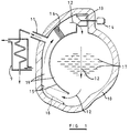
- FIG. 1 there is shown diagrammatically a sectional representation of one form of apparatus in accordance with the invention for energy efficient drying of moist material.
- the apparatus comprises an outer casing 10 which is thermally insulated, and gas-tight apart from the provision of an outlet vent 11.
- continuous recirculation of a gas is effected by means of a fan 13 powered by a motor 14 via ducting 15, through a heat source 16 by means of which the gas is heated by transfer to it of sensible energy from the heat source 16, through moist items 17 to which the gas loses heat, through an optional filter 18, and then back again through the heat source 16.
- a condenser 9 is connected to the vent 11 so that most of the sensible and latent energy contained in the steam produced by the evaporation of the moisture from the items 17 is then recovered together with the resulting condensate.
- the heat recovered by the condenser may be used to heat water, for example for the washing of items.
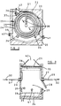
- FIG. 2 and 3 there is shown diagrammatically front and longitudinal sectional views of an alternative form of apparatus for batch drying of moist linen.
- the apparatus comprises a thermally insulated and gas-tight outer casing 20 the inner surface of which is preferably of bright, and thus heat reflecting, stainless steel.
- the duct 22 spans the length of a heat source which is in the form of a rotatable drum 23 made of spiral wound continuous steel tube 24, preferably having a smooth matt black and thus heat radiating surface, with approximately half-tube diameter wide spiral gaps 25 between the convolutions.
- the gaps 25 are interrupted at appropriate intervals by narrow matt black smooth stainless steel cross pieces (not shown) to prevent items escaping from within the drum 23 through the gaps.
- the ends of the steel tube 24 forming the drum 23 extend axially at each end of the drum respectively, and pass through rotating unions 26 and 27 which act as bearings.
- a thermally insulated linen insertion and removal door 28, which is gas-tight when closed, is also provided in the outer casing 20.
- both ends of the steel tube 24 may be arranged to emerge through a common rotating union acting also as a bearing located in place of the first rotating union 26, thus eliminating the need for the second rotating union 27. This may improve access to the drum through the door 28.
- the end of the steel tube 24 which, in the Figure 2 and 3 arrangement, emerges through the second rotating union 27, is led back to the common rotating union through one of four ribs (not shown) fixed within and along the length of the drum 23 approximately at right angles to the convolutions of the steel tube 24.
- the space 29 within the outer casing 20 is heated by steam, as indicated at 30, being made to flow into the spiral wound steel tube 24 through a first flexible connection 31, and the resulting condensate, indicated at 32, flows out through a second flexible connection 33.
- Rotation of the drum 23 is preferably arranged to be in the direction opposite to that of the winding of the steel tube 24 to ensure that the condensate flows out through the second flexible connection 33.
- the drum 23 rests on rollers 34 and 35 and is rotated by an electric motor (not shown) which may either be arranged to drive the drum directly or may be arranged to drive one or both of the rollers 34, 35.
- an electric motor not shown
- a fan 36 is located in a plenum 37 which spans the drum 23 and is in communication with the duct 22.
- the fan causes a circulation of the gas within the outer casing, as indicated by arrows 38, inwardly through the spiral gaps 25 between the convolutions of the tube 24 and diagonally downwards through the width of the drum before returning to the fan 36 via the semi-cylindrical duct 22.
- the circulation of the gas within the casing, in conjunction with rotation of the drum, causes sufficient turbulence to ensure that the linen being tumbled within the drum, with the aid of ribs (not shown) fixed within and along the length of the drum across and approximately at right angles to the steel tube 24 spiral windings, can be quickly dried both by contact of the various surfaces of the linen with the inwardly facing surfaces of the steam heated tube 24 and by the resulting movement of hot gas through the linen weave.
- an outlet duct 39 Communicating with the interior of the casing 20 are an outlet duct 39, controlled by a spring-loaded valve 40, and a valve-controlled inlet duct 41.
- a further valve-controlled exhaust duct 42 communicates with the plenum 37.
- the operation of the apparatus is as follows: When the space within the drum 23 has been loaded with moist linen through the door 28 and both the flow of steam 30 into the spiral wound steel tube 24 and rotation of the drum 23 have commenced, the air initially occupying the space 29 within the thermally insulated and gas-tight casing 20 is heated by release of latent energy from the steam 30 within the spiral wound steel tube 24, and transfer of that energy as sensible energy outwards through the walls of the spiral wound steel tube 24 into the air which is being circulated by the fan 36. As the air is heated it begins to expand and, on attainment, within the outer casing 20, of the slight pressure necessary to open the spring-loaded gas outlet valve 40 in the outlet duct 39, the valve 40 opens and the air begins to exhaust through the duct 39.
- the air contained within a typical 1.5 cubic metres of space within the outer casing of a 40kg dry weight capacity tumble dryer will be displaced during approximately the first 4% of the time taken by a drying cycle, by the steam produced by the evaporation of the typically around 20kg weight of residual moisture content in the 40kg dry weight of linen.
- the evaporation of the 20kg of residual moisture will produce around 34 cubic metres of steam at 100kPa pressure, and dividing the 34m3 of steam produced by the around 1.5m3 of vacant space gives around 23 x the volume of the space available within the outer casing.
- a flow meter and/or temperature gauge (not shown) is provided with its sensor placed in the outlet duct 39, and monitors the rate and/or temperature at which steam is emitted through the outlet duct. As soon as the emission flow rate falls to virtually nil and/or the temperature begins to rise towards that of the steam 30 entering the spiral wound tube 24 (both factors indicating that drying of the linen is complete) the steam supply through the flexible connection 31 is turned off by an automatic valve (not shown) controlled by the aforementioned flow meter and/or temperature gauge.
- the exhaust outlet 42 set in the top of the outer casing 20 is opened by means of appropriate valves (not shown) and the plenum 37 is closed so that the fan 36 diverts through the exhaust outlet 42 the remainder of the steam produced by evaporation of moisture from the linen. Due to the resulting drop in pressure within the space 29 within the outer casing 20, the spring-loaded outlet valve 40 closes automatically and the spring-loaded inwardly opening valve 41 located near the base of the outer casing 20 then opens to allow a flow of ambient air into and through the space 29 within the outer casing.
- a diversion valve (not shown), activated by the thermostat and located in a duct leading away from the exhaust outlet 42, is closed to divert the air then being exhausted to atmosphere.
- Acceleration of the cooling of the still rotating drum 23 and of the linen still being tumbled can be effected by an arrangement (not shown) for passing cold water instead of steam through the tube 24.
- the hot water then produced by heat transfer from the still rotating drum 23 and, to a lesser extent from the linen, into that water, which will then emerge through the second flexible connection 33, can then also be used to wash further linen.
- the electric motors provided to rotate the drum 23 and the fan 36 are stopped automatically and an audible and/or visual signal is given to indicate that the dry linen can be removed from the drum and a further load of moist linen introduced.
- a heating medium other than steam may be employed, for example hot oil or hot combustion gas may be made to flow into the spiral wound steel tube 24 through the first flexible connection 31 and out through the second flexible connection 33.
- heat may be provided by means of a fixed heating medium, for example one or more electrically heated elements located within the spiral wound steel tube 24 comprising the drum 23.
- the spiral wound steel tube 24 comprising the rotatable drum 23 may be replaced by a non-spiral wound arrangement of the steel tube or by an alternative form of drum-shaped rotatable jacket heated by steam or one of the alternative heating media referred to earlier.
- spiral wound tube 24, or its replacement as described in the preceding alternative may be of a material other than steel.
- FIG. 4 there is shown diagrammatically a front sectional view of an alternative form of apparatus for batch or continuous drying of linen according to the invention.
- the drum 43 is non-rotatable and lacks the previously described ribs and rotating unions.
- the drum 43 is otherwise of a spirally-wound tube construction similar to that of the drum 23 of the previously described arrangement.
- Within the fixed drum 43 is a similarly shaped rotatable drum 44 which is not directly heated.
- the inner drum 44 is constructed of perforated sheet steel and has fixed ribs (not shown) within and along its length. Both the inner and outer surfaces of the drum 44 are preferably matt black.
- Other components of the apparatus which correspond to the components of the apparatus of Figures 2 and 3 are given the same reference numerals.
- the flow of air and/or steam, indicated at 45 is induced by the fan 36 and passes through the non-rotatable heat source drum 43, as in the previously described arrangement, and also through the perforations in the rotatable inner drum 44. Because the inner drum 44 is heated by emission of both radiated and convected energy from the heat source drum 44, the inner drum 44 in turn emits radiated, conducted and convected energy from its inner surface into the moist linen being tumbled by rotation of the inner drum 44.
- the heat source may, as appropriate, be located away from direct contact with the linen being dried and may, for example, comprise one or more steam, high pressure hot water, or hot oil heated heater batteries through which the gas in the insulated and gas-tight outer casing is circulated.
- the transfer of sensible energy from the heat source to the moisture in the linen items or other items or commodity being dried is then mainly in the form of the superheat energy of the steam of which the circulating gas is mainly comprised.
- the heat source may be one or more natural gas burners located away from direct contact with the linen and firing directly into a duct or plenum through which the gas contained within the insulated and gas-tight outer casing is circulated.
- the gases comprising the products of combustion assuming a typical 2% oxygen surplus in them when emitted from the burner or burners, will as the drying process gets under way dilute the gas circulating within the gas-tight outer casing.
- Component Displaced with use of indirect heating: Products of combustion: Displaced with use of direct gas heating: Steam 36 6 42 Nitrogen 2 26 28 Carbon dioxide - 3 3 Oxygen 0.5 0.7 1.2 38.5 35.7 74.2
- the dew point temperature of the displaced gas containing the products of combustion averages just under 90°C, so that when vented and passed through the condenser heating will still be to a useful temperature with the added advantage that the combustion of the natural gas increases the steam volume emitted, so that condensation of the increased volume of steam produces for example an increased volume of hot water and effectively results in the natural gas being burnt at 100% efficiency.
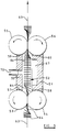
- Figures 5, 6, 7 and 8 show diagrammatically an apparatus in accordance with the invention for continuous as opposed to batch drying of moist items or a moist commodity, for example moist garments.
- the arrangement provides for continuous passage of moist garments into and out of a thermally insulated and substantially gas-tight enclosure.
- the enclosure is defined by two generally parallel thermally insulated wall structures 50, 51 which are spaced apart to define a space 52 between them.
- the space 52 is closed at one end by parallel vertical contra-rotating inlet rollers 53, 54 and at the opposite end by similar outlet rollers 55 and 56.
- each roller is composed of suitable thermally insulative closed cell soft sponge rubber or plastics material.
- the rollers in each pair are parallel and are pressed together with their engaging faces slightly flattened against each other.
- the rollers are also in sealing engagement with concave end faces 57, 58, 59 and 60 respectively on the wall structures 50 and 51.
- the space 52 is further enclosed by an upper horizontal wall member 61 and a lower horizontal wall member 62 (see Figure 6), the wall members being in gas-tight sealing engagement with the upper and lower ends of the rollers so that the space 52 is substantially gas-tight.
- Extending through the space 52 is a stretch of a continuous movable conveyor 63 from which moist garments 64 are suspended on hangers 65 (see Figures 6 and 7).
- the conveyor 63 and rollers 53-56 are driven so that, when the apparatus is in operation, the garments 64 hanging from the conveyor 63 pass into the enclosed space 52 through the nip between the inlet rollers 53 and 54, pass along the enclosed space 52 and then exit from that space through the nip between the outlet rollers 55 and 56.
- the garments are caused to turn parallel to the conveyor 63 as they pass through the nips between the rollers, but extend transversely of the conveyor 63 when passing along the space 52.
- the outer surfaces of the rollers are sufficiently soft and resilient as to be pressed around the conveyor 63 and garments 64 in gas-tight manner so that the enclosed spaced 52 remains substantially sealed and gas-tight.
- the wall structure 51 of the enclosure is formed with a vertical baffle 66 which provides a chamber 67 which extends along substantially the whole length of the space 52 but is open at its upper and lower ends. Disposed in the space 67 is a motor-driven fan 68 and a heat source 69. A vent 70 leads outwardly from the lower part of the space 52 through the wall structure 50.
- the gas within the enclosed space 52 is impelled upwardly through the space 67 by the fan 68 and over the heat source 69, before emerging through the aperture 71 at the upper end of the baffle 66, as indicated by the arrow 72.
- the gas then circulates downwardly around and between the garments 64 as indicated by the arrows 73 and then re-enters the space 67 through the lower aperture 74.
- the enclosure 52 contains air, and as the air is circulated over the heat source 69 and becomes heated it warms and vaporises the moisture in the garments. As the moisture is vaporised and expands, the air initially in the enclosed space 52 is discharged through the vent 70 with an increasing proportion of steam. As the circulating gaseous mixture continues to be heated it eventually consists substantially entirely of superheated steam. The superheated steam passes around and between the garments 64 passing successively through the enclosed space 52, drying the garments, the excess superheated steam being discharged through the vent 70 where it is condensed by a condenser (not shown) to effect heat recovery, as in the previously described arrangements.
- a condenser not shown
- the circulation of the superheated steam within the space 52 takes place at around atmospheric pressure so that there is not a significant pressure difference between the space 52 and the ambient atmosphere outside the apparatus.
- the engagement between the rollers 53, 54 and 55, 56, and between the rollers and the wall structures, does not therefore have to resist a substantial pressure difference.
- one or more filters may be provided for the removal of lint and/or other debris from the recirculating and/or vented gas flows.
- the minimum drying temperature when using the method according to the invention is also 100°C if the pressure within the thermally insulated and gas-tight enclosure is also atmospheric.
- the maximum drying temperature can be controlled thermostatically as desired at above 100°C.
- a controlled reduction in the pressure within the enclosure can be induced.
- the pressure may be reduced to 50kPa at which partial vacuum the dew point temperature of steam is reduced to 81.35°C.
- the minimum drying temperature can thus be brought below 100°C so that by thermostatically controlling the maximum drying temperature to, for example 95°C, items or commodities which are sensitive to temperatures above 95°C can also be dried.
- Downstream of the extraction fan most of the sensible and latent energy contained in the steam produced by the evaporation of the moisture from the items or commodity being dried is then recovered, together with the resulting condensate, as previously described.
- Providing an extraction fan at the outlet vent of any apparatus according to the present invention, in particular for continuous drying, can allow equalisation of the pressures inside and outside the enclosure, so that efficiency reducing ingress of air into the enclosure, or wasteful egress of steam from the enclosure, is prevented, in particular through the locations where the moist items pass into and out of the enclosure.
- Enhancement of the performance of apparatus according to the invention may be achieved by replacing conventional sheet metal construction of the main fixed components by casting the thermally insulated and gas-tight outer shell or casing in one piece with appropriate lugs, bearings, etc., embedded in the casting.
- a known two-component modified isocyanurate system producing a rigid non-porous foam resistant to water and water vapour penetration and to drying temperatures of up to 180°C and possessing high compressive tensile and shear strength combined with a low K value of around 0.02W/mK.
- the energy required to drive the fan is not, as in known drying methods, finally dissipated and thus wasted by emission to atmosphere as sensible energy, but is retained within the thermally insulated and gas-tight outer shell or casing. That energy therefore contributes to the heating and evaporation of the moisture from the material being dried, and thus serves to reduce the amount of sensible energy required to be drawn from the heat source.
- a further gas for example air
- the injection of the further gas may be controlled in proportion to the amount of steam being discharged from the enclosure, either in order to improve the condition of the dried material without significantly lowering the dew point temperature of the steam, containing the injected further gas, being discharged, or in order so to lower the dew point temperature of the discharged steam as to reduce the drying temperature range, thus enabling materials sensitive to higher temperatures to be dried while not significantly lowering the dew point.
Landscapes
- Engineering & Computer Science (AREA)
- Textile Engineering (AREA)
- Drying Of Solid Materials (AREA)
- Processing And Handling Of Plastics And Other Materials For Molding In General (AREA)
- Control And Other Processes For Unpacking Of Materials (AREA)
- Treatment Of Fiber Materials (AREA)
- Detail Structures Of Washing Machines And Dryers (AREA)
- Accessory Of Washing/Drying Machine, Commercial Washing/Drying Machine, Other Washing/Drying Machine (AREA)
Abstract
Description
- The invention relates to a method and apparatus for energy efficient drying of moist material. The invention is particularly, but not exclusively, applicable to the drying of garments after washing in a laundry establishment. However, the expression "moist material" includes moist commodities of all kinds as well as individual items, such as garments.
- Most conventional drying methods and apparatus, such as laundry tumble dryers, employ air as the medium for transporting sensible heat energy from a heat source into the moisture in the material being dried in order first to heat and then to evaporate the moisture, and then to carry away the steam produced by that evaporation. Such methods and apparatus are inefficient in that typically up to around 75% of the sensible energy drawn from the heat source is wasted, mainly by emission of hot air to atmosphere, while the partly sensible but mainly latent energy in the steam produced by the evaporation of the moisture is not recovered as this too is emitted hot to atmosphere.
- In such known drying methods and apparatus the kinetic energy required to provide the fan power to blow the air over the heat source and through the material being dried is finally dissipated and thus also wasted by emission to atmosphere as additional sensible energy within the steam and the air carrying it away. Thermal insulation of the apparatus is also generally inadequate for preventing significant loss of heat.
- In known forms of apparatus heat exchange and air recirculation methods and apparatus are sometimes employed to reduce the wastage of sensible energy within the hot emission to atmosphere. For example, there may be provision for cross flow heat exchange between the hot air and steam emission and the cool ambient air being drawn towards the heat source to make use of part of the sensible energy which is otherwise wasted. Also, recirculation of a proportion of the hot air and steam emission back over the heat source may be employed to reduce the volume of cool ambient air required and thus reduce the amount of sensible energy to be transferred from the heat source.
- Probably the best of the known recirculation methods typically reduces the total amount of sensible energy transferred from the heat source by around 40% by reducing the sensible energy wastage referred to earlier (typically up to about 75%) by around 50%. Other known recirculation or heat exchange methods tend to provide smaller wastage reductions.
- Because the dew point temperature of the emission, even when the best of the known recirculation methods is employed, seldom exceeds 40° to 50°C, useful recovery of the latent energy from the steam contained within the emission, for example by condensation in a condenser to heat water, cannot viably be effected.
- Another known form of drying apparatus sets out to achieve 100% air recirculation and thereby eliminate the need to emit air and steam through ducting. In such apparatus the steam contained within what would otherwise be the hot air and steam emission is condensed out of the recirculating air flow onto a coil cooled by a continuous flow of cold water passing through it. At the same time the heat from the circulating air is transferred to the water and both the resulting condensate and the only slightly warmed water flow to drain, carrying with them virtually all of the thus wasted energy input. Such arrangement is commonly used in domestic tumble dryers. In commercial circumstances, however, where mains water is charged for by volume and not by a fixed annual Domestic Water Rate, or where means of cooling the water would need to be provided, such a method of avoiding the need for emission ducting and providing a flow of only slightly warmed water would not be viable.
- In another known method of drying moist material, the drying medium is superheated steam which is generated from an external source and is then injected into an enclosure containing a batch of material to be dried, the superheated steam being recirculated over the material until it reaches the required dryness. Forms of apparatus using this method are disclosed in CH-A-272894 and EP-A-0101074.
- In CH-A-272894 the enclosure is initially filled with air which is displaced by the introduction of steam, nitrogen or other suitable medium from an outside source. In EP-A-0101074 pre-generated live steam is again injected into the drying enclosure from an external source. Air is subsequently excluded from the enclosure by ensuring that there is a positive pressure within the enclosure.
- In both of these arrangements, during initial injection of the steam from an external source the steam condenses onto the interior surfaces of the enclosure and onto the moist material itself, thus increasing the amount of moisture which must eventually be evaporated from the material to reach a required degree of dryness. In both cases there is also a substantial waste of thermal energy in steam emitted from the drying enclosure.
- The present invention sets out to eliminate most of the waste of sensible energy transferred from the heat source arising with known drying methods and apparatus as described above, and to allow, for example by heating water to around 90°C , recovery of most of the partly sensible but mainly latent energy in the steam produced by the evaporation of the moisture from the material being dried.
- According to the invention there is provided a method of drying moist material in an enclosure, comprising introducing a batch of material to be dried into a thermally insulated enclosure, recirculating superheated steam over the batch of material until the material reaches a required dryness, while allowing a portion of the steam to be discharged from the enclosure through a vent, and removing the batch of dried material from the enclosure, characterised by the initial step of recirculating between a heat source and the batch of material a gas, other than pure steam, which initially fills the enclosure, whereby said gas becomes heated and produces steam from the moisture in the material, which steam increasingly displaces the initial gas from the enclosure and continues to be heated by recirculation past said heat source, thereby becoming superheated, said heating of the moisture in the material constituting at least the major source of the steam recirculating in the enclosure, and the step of recovering at least part of the thermal energy of the steam discharged from the enclosure through said vent, the enclosure being substantially gas-tight, at least while the step of recirculating the superheated steam is being carried out, except for said vent.
- The thermal energy may be recovered from said discharged steam by at least partly condensing the steam and using the latent and sensible heat therefrom to heat a further fluid by heat exchange therewith.
- The method may include the step of ceasing recirculation of the steam before removing the batch of dried material from the enclosure.
- The method may also include the further step, after ceasing recirculation of the steam and before removing the batch of dried material from the enclosure, of cooling said dried material.
- One particular form of the method according to the invention is characterised by continuously introducing successive portions of the batch of material to be dried into the enclosure, through said drying location, and out of the enclosure, while maintaining the recirculation of superheated steam, the continuous passing of successive portions of the batch of material out of the drying location beginning only after the circulation steam has become superheated, during the aforesaid initial step of the method, while a first portion of said batch of material is in the enclosure.
- In any of the above methods the recirculation of the superheated steam in the enclosure is preferably carried out at substantially atmospheric pressure.
- The heat source may comprise one or more gas burners and the gaseous combustion products from the burners are introduced into the enclosure, said gaseous combustion products diluting the portion of the steam discharged from the enclosure without significantly lowering the dew point temperature thereof.
- The methods according to the invention may also include the step of introducing a further gas into the enclosure during drying, the amount of which further gas is controlled to be in proportion to the amount of steam discharged from the enclosure.
- The invention also provides apparatus for drying moist material comprising an enclosure which is thermally insulated, a drying location within the enclosure, means for recirculating gas through the drying location, and steam venting means leading from the enclosure, characterised by the absence of a steam inlet pipe for injection of heating steam into the enclosure and the provision of a heat source and power-driven fan means located within said enclosure, said heat source being capable of supplying sufficient thermal energy to the recirculating gas, without injection of steam into the recirculating gas, to produce steam from moist material at the drying location and to superheat the steam, said enclosure being capable of being rendered substantially gas-tight, during said recirculation, apart from said steam venting means, and means for recovering at least part of the thermal energy of steam discharged from the enclosure through said venting means.
- Said heat source may comprise one or more gas burners. Means may be provided for introducing a further gas into the enclosure during drying.
- The drying location may be defined by a container within the enclosure, said container being formed with apertures through which the recirculating gas may pass. The walls of the container may include passages, means being provided for passing heated fluid medium through said passages, whereby to provide the heat source.
- Means may be provided for passing a fluid heating medium or a fluid cooling medium selectively through said passages.
- The container is preferably rotatable. Alternatively, however, the container may enclose a rotatable subsidiary container, in which the material to be dried may be placed, said subsidiary container also being formed with apertures through which the recirculating gas may pass.
- Means may be provided for passing a cooling gas through the drying location, after drying of material at said location has been completed.
- For continuous drying the enclosure may be provided with substantially gas-tight inlet and outlet means, a movable conveyor being provided to transport batches of material to be dried into and out of the enclosure through said inlet and outlet means respectively, in substantially gas-tight manner. The inlet and outlet means may each comprise a pair of cooperating rollers having flexibly resilient engaging outer surfaces, adapted to embrace the conveyor, and material carried thereby, as it passes through the nip between the rollers.
- In any of the forms of apparatus according to the invention a condenser may be provided for recovering at least part of the thermal energy of steam discharged from the enclosure through said venting means.
- The following is a detailed description of embodiments of the invention, by way of example, referring to the accompanying drawings in which:
- Figure 1 is a diagrammatic section through one form of drying apparatus according to the invention,
- Figure 2 is a similar view through an alternative form of drying apparatus,
- Figure 3 is a diagrammatic longitudinal section through the apparatus of Figure 2,
- Figure 4 is a diagrammatic section through a further form of drying apparatus,
- Figure 5 is a diagrammatic horizontal section through a form of drying apparatus suitable for the continuous drying of garments,
- Figure 6 is an end view of the apparatus of Figure 5,
- Figure 7 is a vertical transverse section through the apparatus of Figures 5 and 6, and
- Figure 8 is a longitudinal vertical section through the apparatus of Figures 5-7.
- Referring to Figure 1, there is shown diagrammatically a sectional representation of one form of apparatus in accordance with the invention for energy efficient drying of moist material. The apparatus comprises an
outer casing 10 which is thermally insulated, and gas-tight apart from the provision of anoutlet vent 11. Within thecasing 10 continuous recirculation of a gas, the circulation being indicated byarrows 12, is effected by means of afan 13 powered by amotor 14 via ducting 15, through a heat source 16 by means of which the gas is heated by transfer to it of sensible energy from the heat source 16, throughmoist items 17 to which the gas loses heat, through anoptional filter 18, and then back again through the heat source 16. In the course of recirculation of the gas, sensible energy is continuously transferred from the heat source 16 to the moisture in theitems 17 being dried. The gas, which initially normally consists of air occupying thespaces 19 within thecasing 10, is increasingly displaced by the steam produced by the resulting evaporation of the moisture from theitems 17 as the temperature rises. When the minimum temperature of the mixture of air and steam reaches the boiling temperature of the moisture, all of the sensible energy being transferred to the circulating gas from the heat source 16 can then be taken up by the steam in the gas in the form of superheating of the steam. - Initially the displaced air is vented through the
outlet vent 11, and then the gas including a rapidly increasing proportion of the steam being produced is vented, and then for the remainder of the batch or continuous process time virtually pure steam is vented through theoutlet vent 11. A condenser 9 is connected to thevent 11 so that most of the sensible and latent energy contained in the steam produced by the evaporation of the moisture from theitems 17 is then recovered together with the resulting condensate. The heat recovered by the condenser may be used to heat water, for example for the washing of items. - Referring to Figures 2 and 3, there is shown diagrammatically front and longitudinal sectional views of an alternative form of apparatus for batch drying of moist linen. The apparatus comprises a thermally insulated and gas-tight
outer casing 20 the inner surface of which is preferably of bright, and thus heat reflecting, stainless steel. Within the casing there is provided an inner generally part-cylindrical shell 21, also preferably of bright stainless steel sheet, which provides between itself and the inner surface of the outer casing 20 aduct 22 extending along the length of the outer casing. Theduct 22 spans the length of a heat source which is in the form of arotatable drum 23 made of spiral woundcontinuous steel tube 24, preferably having a smooth matt black and thus heat radiating surface, with approximately half-tube diameterwide spiral gaps 25 between the convolutions. Thegaps 25 are interrupted at appropriate intervals by narrow matt black smooth stainless steel cross pieces (not shown) to prevent items escaping from within thedrum 23 through the gaps. - The ends of the
steel tube 24 forming thedrum 23 extend axially at each end of the drum respectively, and pass through rotatingunions removal door 28, which is gas-tight when closed, is also provided in theouter casing 20. - In an alternative arrangement (not shown) both ends of the
steel tube 24 may be arranged to emerge through a common rotating union acting also as a bearing located in place of the firstrotating union 26, thus eliminating the need for the secondrotating union 27. This may improve access to the drum through thedoor 28. In this alternative arrangement the end of thesteel tube 24 which, in the Figure 2 and 3 arrangement, emerges through the secondrotating union 27, is led back to the common rotating union through one of four ribs (not shown) fixed within and along the length of thedrum 23 approximately at right angles to the convolutions of thesteel tube 24. - The
space 29 within theouter casing 20 is heated by steam, as indicated at 30, being made to flow into the spiral woundsteel tube 24 through a firstflexible connection 31, and the resulting condensate, indicated at 32, flows out through a secondflexible connection 33. Rotation of thedrum 23 is preferably arranged to be in the direction opposite to that of the winding of thesteel tube 24 to ensure that the condensate flows out through the secondflexible connection 33. - The
drum 23 rests onrollers rollers - A
fan 36 is located in aplenum 37 which spans thedrum 23 and is in communication with theduct 22. The fan causes a circulation of the gas within the outer casing, as indicated byarrows 38, inwardly through thespiral gaps 25 between the convolutions of thetube 24 and diagonally downwards through the width of the drum before returning to thefan 36 via thesemi-cylindrical duct 22. The circulation of the gas within the casing, in conjunction with rotation of the drum, causes sufficient turbulence to ensure that the linen being tumbled within the drum, with the aid of ribs (not shown) fixed within and along the length of the drum across and approximately at right angles to thesteel tube 24 spiral windings, can be quickly dried both by contact of the various surfaces of the linen with the inwardly facing surfaces of the steamheated tube 24 and by the resulting movement of hot gas through the linen weave. - Communicating with the interior of the
casing 20 are anoutlet duct 39, controlled by a spring-loadedvalve 40, and a valve-controlledinlet duct 41. A further valve-controlledexhaust duct 42 communicates with theplenum 37. - The operation of the apparatus is as follows: When the space within the
drum 23 has been loaded with moist linen through thedoor 28 and both the flow ofsteam 30 into the spiral woundsteel tube 24 and rotation of thedrum 23 have commenced, the air initially occupying thespace 29 within the thermally insulated and gas-tight casing 20 is heated by release of latent energy from thesteam 30 within the spiral woundsteel tube 24, and transfer of that energy as sensible energy outwards through the walls of the spiral woundsteel tube 24 into the air which is being circulated by thefan 36. As the air is heated it begins to expand and, on attainment, within theouter casing 20, of the slight pressure necessary to open the spring-loadedgas outlet valve 40 in theoutlet duct 39, thevalve 40 opens and the air begins to exhaust through theduct 39. - As steam is produced by evaporation of moisture from the linen, the proportion of steam in the air entrapped within the
outer casing 20 rises rapidly, due to continued release of latent energy from thesteam 30 within the spiral woundsteel tube 24, and the remaining air is quickly displaced from within thecasing 20 through theoutlet duct 39, to be followed by a continuous flow of steam. - By way of example, the air contained within a typical 1.5 cubic metres of space within the outer casing of a 40kg dry weight capacity tumble dryer will be displaced during approximately the first 4% of the time taken by a drying cycle, by the steam produced by the evaporation of the typically around 20kg weight of residual moisture content in the 40kg dry weight of linen. The evaporation of the 20kg of residual moisture will produce around 34 cubic metres of steam at 100kPa pressure, and dividing the 34m³ of steam produced by the around 1.5m³ of vacant space gives around 23 x the volume of the space available within the outer casing.
- A flow meter and/or temperature gauge (not shown) is provided with its sensor placed in the
outlet duct 39, and monitors the rate and/or temperature at which steam is emitted through the outlet duct. As soon as the emission flow rate falls to virtually nil and/or the temperature begins to rise towards that of thesteam 30 entering the spiral wound tube 24 (both factors indicating that drying of the linen is complete) the steam supply through theflexible connection 31 is turned off by an automatic valve (not shown) controlled by the aforementioned flow meter and/or temperature gauge. - At the same time as that automatic valve is turned off the
exhaust outlet 42 set in the top of theouter casing 20 is opened by means of appropriate valves (not shown) and theplenum 37 is closed so that thefan 36 diverts through theexhaust outlet 42 the remainder of the steam produced by evaporation of moisture from the linen. Due to the resulting drop in pressure within thespace 29 within theouter casing 20, the spring-loadedoutlet valve 40 closes automatically and the spring-loaded inwardly openingvalve 41 located near the base of theouter casing 20 then opens to allow a flow of ambient air into and through thespace 29 within the outer casing. Since this ambient air is heavier than the steam remaining within theouter casing 20, steam will at first be emitted through theexhaust outlet 42 and both the latent and sensible energy in this steam, and that emitted through the spring-loadedoutlet valve 40, is recovered by passing it into a condenser (not shown) and is used to heat laundry washing water or for other purposes. The condensate which is then emitted from the condenser is effectively distilled water and is either used as such or is added back to the supply of softened laundry water. - As soon as the temperature of the emission through the
exhaust outlet 42, which is monitored by a thermostat (not shown), begins to fall, indicating that the remaining steam has been exhausted, a diversion valve (not shown), activated by the thermostat and located in a duct leading away from theexhaust outlet 42, is closed to divert the air then being exhausted to atmosphere. - Acceleration of the cooling of the still rotating
drum 23 and of the linen still being tumbled can be effected by an arrangement (not shown) for passing cold water instead of steam through thetube 24. The hot water then produced by heat transfer from the still rotatingdrum 23 and, to a lesser extent from the linen, into that water, which will then emerge through the secondflexible connection 33, can then also be used to wash further linen. As soon as thedrum 23 and the linen have been sufficiently cooled as required for removal of the linen, as indicated by a thermostat located within theexhaust outlet 42, the electric motors provided to rotate thedrum 23 and thefan 36 are stopped automatically and an audible and/or visual signal is given to indicate that the dry linen can be removed from the drum and a further load of moist linen introduced. - As an alternative arrangement to the steam heating described above, a heating medium other than steam may be employed, for example hot oil or hot combustion gas may be made to flow into the spiral wound
steel tube 24 through the firstflexible connection 31 and out through the secondflexible connection 33. - In another alternative arrangement according to the present invention, heat may be provided by means of a fixed heating medium, for example one or more electrically heated elements located within the spiral wound
steel tube 24 comprising thedrum 23. In a further alternative arrangement according to the invention, the spiral woundsteel tube 24 comprising therotatable drum 23 may be replaced by a non-spiral wound arrangement of the steel tube or by an alternative form of drum-shaped rotatable jacket heated by steam or one of the alternative heating media referred to earlier. - In any of the described arrangements the spiral wound
tube 24, or its replacement as described in the preceding alternative, may be of a material other than steel. - Referring to Figure 4, there is shown diagrammatically a front sectional view of an alternative form of apparatus for batch or continuous drying of linen according to the invention. In this arrangement the
drum 43 is non-rotatable and lacks the previously described ribs and rotating unions. Thedrum 43 is otherwise of a spirally-wound tube construction similar to that of thedrum 23 of the previously described arrangement. Within the fixeddrum 43 is a similarly shaped rotatable drum 44 which is not directly heated. The inner drum 44 is constructed of perforated sheet steel and has fixed ribs (not shown) within and along its length. Both the inner and outer surfaces of the drum 44 are preferably matt black. Other components of the apparatus which correspond to the components of the apparatus of Figures 2 and 3 are given the same reference numerals. - In this alternative arrangement the flow of air and/or steam, indicated at 45, is induced by the
fan 36 and passes through the non-rotatableheat source drum 43, as in the previously described arrangement, and also through the perforations in the rotatable inner drum 44. Because the inner drum 44 is heated by emission of both radiated and convected energy from the heat source drum 44, the inner drum 44 in turn emits radiated, conducted and convected energy from its inner surface into the moist linen being tumbled by rotation of the inner drum 44. - In this and any previously described arrangement according to the invention the heat source may, as appropriate, be located away from direct contact with the linen being dried and may, for example, comprise one or more steam, high pressure hot water, or hot oil heated heater batteries through which the gas in the insulated and gas-tight outer casing is circulated. The transfer of sensible energy from the heat source to the moisture in the linen items or other items or commodity being dried is then mainly in the form of the superheat energy of the steam of which the circulating gas is mainly comprised.
- In a further alternative arrangements, not shown, according to the invention, the heat source may be one or more natural gas burners located away from direct contact with the linen and firing directly into a duct or plenum through which the gas contained within the insulated and gas-tight outer casing is circulated.
- When this alternative direct natural gas burning apparatus is employed, the gases comprising the products of combustion, assuming a typical 2% oxygen surplus in them when emitted from the burner or burners, will as the drying process gets under way dilute the gas circulating within the gas-tight outer casing. For example, during a typical linen batch drying cycle to remove around 20kg of moisture from around 40kg of linen, the approximate cubic metre volumes of each of the main components of the displaced gas vented into a condenser as earlier described will alter as indicated below:
Component: Displaced with use of indirect heating: Products of combustion: Displaced with use of direct gas heating: Steam 36 6 42 Nitrogen 2 26 28 Carbon dioxide - 3 3 Oxygen 0.5 0.7 1.2 38.5 35.7 74.2 - The dew point temperature of the displaced gas containing the products of combustion averages just under 90°C, so that when vented and passed through the condenser heating will still be to a useful temperature with the added advantage that the combustion of the natural gas increases the steam volume emitted, so that condensation of the increased volume of steam produces for example an increased volume of hot water and effectively results in the natural gas being burnt at 100% efficiency.
- Figures 5, 6, 7 and 8 show diagrammatically an apparatus in accordance with the invention for continuous as opposed to batch drying of moist items or a moist commodity, for example moist garments. The arrangement provides for continuous passage of moist garments into and out of a thermally insulated and substantially gas-tight enclosure.
- Referring to Figure 5, the enclosure is defined by two generally parallel thermally insulated
wall structures space 52 between them. Thespace 52 is closed at one end by parallel vertical contra-rotatinginlet rollers similar outlet rollers - The outer surface of each roller is composed of suitable thermally insulative closed cell soft sponge rubber or plastics material. The rollers in each pair are parallel and are pressed together with their engaging faces slightly flattened against each other. The rollers are also in sealing engagement with concave end faces 57, 58, 59 and 60 respectively on the
wall structures space 52 is further enclosed by an upperhorizontal wall member 61 and a lower horizontal wall member 62 (see Figure 6), the wall members being in gas-tight sealing engagement with the upper and lower ends of the rollers so that thespace 52 is substantially gas-tight. - Extending through the
space 52 is a stretch of a continuousmovable conveyor 63 from whichmoist garments 64 are suspended on hangers 65 (see Figures 6 and 7). - The
conveyor 63 and rollers 53-56 are driven so that, when the apparatus is in operation, thegarments 64 hanging from theconveyor 63 pass into the enclosedspace 52 through the nip between theinlet rollers space 52 and then exit from that space through the nip between theoutlet rollers conveyor 63 as they pass through the nips between the rollers, but extend transversely of theconveyor 63 when passing along thespace 52. As best seen in Figure 6, the outer surfaces of the rollers are sufficiently soft and resilient as to be pressed around theconveyor 63 andgarments 64 in gas-tight manner so that the enclosed spaced 52 remains substantially sealed and gas-tight. - Referring in particular to Figure 7, the
wall structure 51 of the enclosure is formed with avertical baffle 66 which provides achamber 67 which extends along substantially the whole length of thespace 52 but is open at its upper and lower ends. Disposed in thespace 67 is a motor-drivenfan 68 and aheat source 69. Avent 70 leads outwardly from the lower part of thespace 52 through thewall structure 50. - In operation, the gas within the enclosed
space 52 is impelled upwardly through thespace 67 by thefan 68 and over theheat source 69, before emerging through theaperture 71 at the upper end of thebaffle 66, as indicated by thearrow 72. The gas then circulates downwardly around and between thegarments 64 as indicated by thearrows 73 and then re-enters thespace 67 through the lower aperture 74. - As in the previously described arrangements, initially the
enclosure 52 contains air, and as the air is circulated over theheat source 69 and becomes heated it warms and vaporises the moisture in the garments. As the moisture is vaporised and expands, the air initially in the enclosedspace 52 is discharged through thevent 70 with an increasing proportion of steam. As the circulating gaseous mixture continues to be heated it eventually consists substantially entirely of superheated steam. The superheated steam passes around and between thegarments 64 passing successively through the enclosedspace 52, drying the garments, the excess superheated steam being discharged through thevent 70 where it is condensed by a condenser (not shown) to effect heat recovery, as in the previously described arrangements. - The circulation of the superheated steam within the
space 52 takes place at around atmospheric pressure so that there is not a significant pressure difference between thespace 52 and the ambient atmosphere outside the apparatus. The engagement between therollers - In any of the arrangements according to the invention described above, one or more filters may be provided for the removal of lint and/or other debris from the recirculating and/or vented gas flows.
- Because the dew point temperature of steam at atmospheric pressure is 100°C, the minimum drying temperature when using the method according to the invention is also 100°C if the pressure within the thermally insulated and gas-tight enclosure is also atmospheric. The maximum drying temperature can be controlled thermostatically as desired at above 100°C.
- By providing an extraction fan at the outlet vent of any apparatus according to the present invention, a controlled reduction in the pressure within the enclosure can be induced. For example the pressure may be reduced to 50kPa at which partial vacuum the dew point temperature of steam is reduced to 81.35°C. The minimum drying temperature can thus be brought below 100°C so that by thermostatically controlling the maximum drying temperature to, for example 95°C, items or commodities which are sensitive to temperatures above 95°C can also be dried. Downstream of the extraction fan most of the sensible and latent energy contained in the steam produced by the evaporation of the moisture from the items or commodity being dried is then recovered, together with the resulting condensate, as previously described.
- Providing an extraction fan at the outlet vent of any apparatus according to the present invention, in particular for continuous drying, can allow equalisation of the pressures inside and outside the enclosure, so that efficiency reducing ingress of air into the enclosure, or wasteful egress of steam from the enclosure, is prevented, in particular through the locations where the moist items pass into and out of the enclosure.
- Enhancement of the performance of apparatus according to the invention, combined with rationalisation of the manufacture of, in particular, the outer shell or casing, may be achieved by replacing conventional sheet metal construction of the main fixed components by casting the thermally insulated and gas-tight outer shell or casing in one piece with appropriate lugs, bearings, etc., embedded in the casting. There may be employed for that purpose a known two-component modified isocyanurate system producing a rigid non-porous foam resistant to water and water vapour penetration and to drying temperatures of up to 180°C and possessing high compressive tensile and shear strength combined with a low K value of around 0.02W/mK.
- In all of the described embodiments of the apparatus according to the present invention described above, the energy required to drive the fan is not, as in known drying methods, finally dissipated and thus wasted by emission to atmosphere as sensible energy, but is retained within the thermally insulated and gas-tight outer shell or casing. That energy therefore contributes to the heating and evaporation of the moisture from the material being dried, and thus serves to reduce the amount of sensible energy required to be drawn from the heat source.
- In any of the arrangements described above, a further gas, for example air, may be injected into the drying enclosure while drying is taking place. The injection of the further gas may be controlled in proportion to the amount of steam being discharged from the enclosure, either in order to improve the condition of the dried material without significantly lowering the dew point temperature of the steam, containing the injected further gas, being discharged, or in order so to lower the dew point temperature of the discharged steam as to reduce the drying temperature range, thus enabling materials sensitive to higher temperatures to be dried while not significantly lowering the dew point.
- While linen or garments have been cited by way of example within the preceding detailed descriptions, the use of the invention is not confined to the energy efficient drying of linen, and the methods and apparatus according to the invention can be used for the energy efficient drying of any other moist items or commodities having sufficient particle size and temperature tolerance.
Claims (20)
- A method of drying moist material in an enclosure, comprising introducing a batch of material (17) to be dried into a thermally insulated enclosure (10), recirculating superheated steam over the batch of material until the material reaches a required dryness, while allowing a portion of the steam to be discharged from the enclosure through a vent (11), the enclosure being except for said vent (11) substantially gas-tight, at least while the step of recirculating the superheated steam is being carried out, and removing the batch of dried material from the enclosure, characterised by the initial step of recirculating between a heat source (16) and the batch of material (17) a gas, other than pure steam, which initially fills the enclosure, whereby said gas becomes heated and produces steam from the moisture in the material, which steam increasingly displaces the initial gas from the enclosure and continues to be heated by recirculation past said heat source, thereby becoming superheated, said heating of the moisture in the material (17) constituting at least the major source of the steam recirculating in the enclosure, and the step of recovering at least part of the thermal energy of the steam discharged from the enclosure through said vent (11).
- A method according to Claim 1, characterised in that thermal energy is recovered from said discharged steam by at least partly condensing the steam and using the latent and sensible heat therefrom to heat a further fluid by heat exchange therewith.
- A method according to Claim 1 or Claim 2, including the step of ceasing recirculation of the steam before removing the batch of dried material from the enclosure.
- A method according to Claim 3, including the further step, after ceasing recirculation of the steam and before removing the batch of dried material from the enclosure, of cooling said dried material.
- A method according to Claim 1 or Claim 2, characterised by continuously introducing successive portions of the batch of material to be dried (64, Fig. 5) into the enclosure (50,51,53,54,55,56, Fig.5), through said drying location (52), and out of the enclosure, while maintaining the recirculation of superheated steam, the continuous passing of successive portions of the batch of material out of the drying location beginning only after the circulation steam has become superheated, during the aforesaid initial step of the method, while a first portion of said batch of material is in the enclosure.
- A method according to any of Claims 1 to 5, characterised in that the recirculation of the superheated steam in the enclosure is carried out at substantially atmospheric pressure.
- A method according to any of Claims 1 to 6, characterised in that the heat source comprises one or more gas burners and the gaseous combustion products from the burners are introduced into the enclosure, said gaseous combustion products diluting the portion of the steam discharged from the enclosure without significantly lowering the dew point temperature thereof.
- A method according to any of Claims 1 to 7, including the step of introducing a further gas into the enclosure during drying, the amount of which further gas is controlled to be in proportion to the amount of steam discharged from the enclosure.
- Apparatus for drying moist material comprising an enclosure (10) which is thermally insulated, a heat source (16) located within the enclosure (10), a drying location within the enclosure, means (13) for recirculating gas through the drying location, and steam venting means (11) leading from the enclosure, said enclosure being capable of being rendered substantially gas-tight, during said recirculation, apart from said steam venting means, characterised by the absence of a steam inlet pipe for injection of heating steam into the enclosure and the provision of power-driven fan means (13) located within said enclosure, said heat source being capable of supplying sufficient thermal energy to the recirculating gas, without injection of steam into the recirculating gas, to produce steam from moist material (17) at the drying location and to superheat the steam, and means (9) for recovering at least part of the thermal energy of steam discharged from the enclosure through said venting means.
- Apparatus according to Claim 9, characterised in that said heat source comprises one or more gas burners.
- Apparatus according to Claim 9 or Claim 10, including means for introducing a further gas into the enclosure during drying.
- Apparatus according to any of Claims 9 to 11, characterised in that the drying location is defined by a container (23, Fig. 2) within the enclosure (20), said container being formed with apertures (25) through which the recirculating gas may pass.
- Apparatus according to Claim 12, characterised in that the walls of the container (23) include passages (24), and means are provided for passing heated fluid medium through said passages, whereby to provide the heat source.
- Apparatus according to Claim 13, including means for passing a fluid heating medium or a fluid cooling medium selectively through said passages (24).
- Apparatus according to any of Claims 12 to 14, characterised in that said container (23) is rotatable.
- Apparatus according to any of Claims 12 to 14, characterised in that said container (43, Fig. 4) encloses a rotatable subsidiary container (44), in which the material to be dried may be placed, said subsidiary container also being formed with apertures through which the recirculating gas may pass.
- Apparatus according to any of Claims 9 to 16, characterised in that means (41) are provided for passing a cooling gas through the drying location, after drying of material at said location has been completed.
- Apparatus according to any of Claims 9 to 11, characterised in that the enclosure (Fig. 5) is provided with substantially gas-tight inlet (53, 54) and outlet (55, 56) means, and a movable conveyor (63) is provided to transport batches of material (64) to be dried into and out of the enclosure through said inlet and outlet means respectively, in substantially gas-tight manner.
- Apparatus according to Claim 18, characterised in that the inlet and outlet means each comprise a pair of cooperating rollers (53,54,55,56) having flexibly resilient engaging outer surfaces, adapted to embrace the conveyor (63), and material (64) carried thereby, as it passes through the nip between the rollers.
- Apparatus according to any of Claims 9 to 19, characterised in that a condenser (9, Fig. 1) is provided for recovering at least part of the thermal energy of steam discharged from the enclosure (10) through said venting means (11).
Applications Claiming Priority (7)
| Application Number | Priority Date | Filing Date | Title |
|---|---|---|---|
| GB878726456A GB8726456D0 (en) | 1987-11-12 | 1987-11-12 | Tumble drying |
| GB8726456 | 1987-11-12 | ||
| GB8728603 | 1987-12-08 | ||
| GB878728603A GB8728603D0 (en) | 1987-11-12 | 1987-12-08 | Method & apparatus for energy efficient tumble drying |
| GB8813171 | 1988-06-03 | ||
| GB8813171A GB2209383B (en) | 1987-11-12 | 1988-06-03 | Method and apparatus for energy efficient drying |
| PCT/GB1988/000968 WO1989004392A1 (en) | 1987-11-12 | 1988-11-09 | Method and apparatus for energy efficient drying |
Publications (2)
| Publication Number | Publication Date |
|---|---|
| EP0395685A1 EP0395685A1 (en) | 1990-11-07 |
| EP0395685B1 true EP0395685B1 (en) | 1994-09-21 |
Family
ID=27263662
Family Applications (1)
| Application Number | Title | Priority Date | Filing Date |
|---|---|---|---|
| EP88910089A Expired - Lifetime EP0395685B1 (en) | 1987-11-12 | 1988-11-09 | Method and apparatus for energy efficient drying |
Country Status (11)
| Country | Link |
|---|---|
| US (1) | US5228211A (en) |
| EP (1) | EP0395685B1 (en) |
| JP (1) | JPH03501813A (en) |
| AT (1) | ATE111980T1 (en) |
| AU (1) | AU611983B2 (en) |
| CA (1) | CA1337152C (en) |
| DE (1) | DE3851636T2 (en) |
| ES (1) | ES2015116A6 (en) |
| FI (1) | FI91891C (en) |
| NO (1) | NO177437C (en) |
| WO (1) | WO1989004392A1 (en) |
Cited By (1)
| Publication number | Priority date | Publication date | Assignee | Title |
|---|---|---|---|---|
| EP2103731A2 (en) | 2008-03-20 | 2009-09-23 | Hans Fladt GmbH | Drying device with at least two drums |
Families Citing this family (27)
| Publication number | Priority date | Publication date | Assignee | Title |
|---|---|---|---|---|
| DE19510001C2 (en) * | 1995-03-22 | 1998-01-22 | Patent Und Innovationsagentur | Drying cabinet with improved energy use |
| FR2745896B1 (en) * | 1996-03-07 | 1998-04-24 | Armines | METHOD AND INSTALLATION FOR DRYING A MASS OF WET FIBROUS MATERIAL, IN PARTICULAR A LAUNDRY MASS |
| FR2785372B1 (en) * | 1998-11-02 | 2001-01-26 | Armines Ass Pour La Rech Et Le | METHOD AND INSTALLATION FOR DRYING A MASS OF FIBROUS MATERIAL |
| SE521337C2 (en) * | 1999-08-09 | 2003-10-21 | Electrolux Ab | Textile washing machine with steam drying |
| DE10030531B4 (en) * | 2000-06-28 | 2004-08-26 | Multitroc Patentverwertungsgesellschaft Mbh & Co.Kg | Method and device for non-iron drying of moist goods, especially damp laundry or clothing |
| JP2004501657A (en) * | 2000-06-28 | 2004-01-22 | マックス−デルブルック−セントラム フュール モレクラーレ メディツィン | How to improve transfection efficiency |
| US20040118010A1 (en) * | 2001-04-24 | 2004-06-24 | Shardlow Andrew Michael | Clothes dryer |
| DE10217432B4 (en) * | 2002-04-18 | 2005-06-02 | Fraunhofer-Gesellschaft zur Förderung der angewandten Forschung e.V. | Method and apparatus for drying and gasifying sludge |
| US7235109B2 (en) * | 2004-04-12 | 2007-06-26 | Kleker Richard G | Apparatus for processing garments including a water and air system |
| US7060106B2 (en) * | 2003-04-15 | 2006-06-13 | Richard George Kleker | Apparatus for washing and drying garments |
| US20050223502A1 (en) * | 2004-04-09 | 2005-10-13 | Kleker Richard G | Apparatus for processing garments including a hanger mechanism |
| KR20050115995A (en) * | 2004-06-04 | 2005-12-08 | 주식회사 대우일렉트로닉스 | Drum type washing machine with ironing function |
| DE102006020003A1 (en) * | 2006-04-26 | 2007-10-31 | Herbert Kannegiesser Gmbh | Method for recovering the heat energy emitted by laundry machines |
| EP2055820B1 (en) * | 2006-05-02 | 2013-04-10 | Electrolux Home Products Corporation N.V. | Steam supplying method and treatment apparatus |
| EP2163678B1 (en) * | 2006-05-02 | 2012-08-15 | Electrolux Home Products Corporation N.V. | Dryer with drying sequence using an additive |
| CN101460671B (en) * | 2006-06-01 | 2011-10-12 | 伊莱克斯家用产品股份有限公司 | Steam supply method and processing equipment |
| KR20090030269A (en) * | 2006-06-01 | 2009-03-24 | 일렉트로룩스 홈 프로덕츠 코오포레이션 엔.브이. | Steam supply method and processing device |
| US20070080613A1 (en) * | 2006-09-20 | 2007-04-12 | Sterlite Optical Technologies Ltd | Storage and transportation device for storing and transporting optical fiber preform and precursors thereof |
| EP2055824B1 (en) * | 2007-11-02 | 2014-07-30 | LG Electronics Inc. | Dryer |
| WO2010029058A1 (en) * | 2008-09-09 | 2010-03-18 | Arcelik Anonim Sirketi | A dryer |
| US20120159801A1 (en) * | 2010-12-28 | 2012-06-28 | Chin-Feng Chang | Dehydrating device |
| US9140396B2 (en) | 2013-03-15 | 2015-09-22 | Water-Gen Ltd. | Dehumidification apparatus |
| US10151060B2 (en) | 2015-11-24 | 2018-12-11 | Water-Gen Ltd | Steam compression dryer |
| IT201900012672A1 (en) | 2019-07-23 | 2021-01-23 | Vallecaudina Energie Rinnovabili S R L | DRYING PROCESS OF SEWAGE SLUDGE AND PLANT TO PRACTICE THIS PROCESS |
| KR102336988B1 (en) * | 2020-01-16 | 2021-12-08 | 엘지전자 주식회사 | A laundry treating apparatus |
| US20220003425A1 (en) * | 2020-07-05 | 2022-01-06 | Kitchen Robotics Ltd | Cooking Apparatus Based on Induction Heating System and Incorporating Cookware Rotation Mechanism |
| CN115090211B (en) * | 2022-06-08 | 2023-09-22 | 苏州思萃热控材料科技有限公司 | An integrated drying and granulating equipment for the preparation of aluminum silicon carbide composite materials |
Family Cites Families (19)
| Publication number | Priority date | Publication date | Assignee | Title |
|---|---|---|---|---|
| CH272894A (en) * | 1946-09-28 | 1951-01-15 | Pluria Ab | Device for drying materials by means of superheated steam. |
| GB617652A (en) * | 1946-10-10 | 1949-02-09 | Humphreys & Glasgow Ltd | Improvements in the method of utilising wet fuels and apparatus therefor |
| US2911729A (en) * | 1956-11-30 | 1959-11-10 | Byron A Wood | Method of and means for steam treating and vibrating garments |
| US3242584A (en) * | 1963-04-29 | 1966-03-29 | Gen Motors Corp | Domestic clothes drying appliance |
| US3644085A (en) * | 1970-06-29 | 1972-02-22 | Mc Graw Edison Co | Garment finisher and method of finishing garments |
| US3766662A (en) * | 1972-01-24 | 1973-10-23 | R Moyer | Apparatus for drying fabrics |
| IT984050B (en) * | 1973-04-20 | 1974-11-20 | Srl Arioli E C | PERFECTED EQUIPMENT FOR SELECTIVE TREATMENT WITH VAPO RE SATURATED OR OVERHEATED OF PRINTED TES SUTI |
| US3921308A (en) * | 1973-11-23 | 1975-11-25 | Challenge Cook Bros Inc | Methods for treating yarn bundles |
| GB1558913A (en) * | 1977-03-31 | 1980-01-09 | Electricity Council | Drying of wet material |
| DE2913427A1 (en) * | 1979-04-04 | 1980-10-16 | Miele & Cie | Hot air circuit in domestic washing machine - extracts vapour to condenser where pressure is nearest to atmospheric |
| DE3015428C2 (en) * | 1980-04-22 | 1982-04-22 | Ranco Inc., 43201 Columbus, Ohio | Drum dryer for drying laundry |
| US4447965A (en) * | 1980-06-04 | 1984-05-15 | General Electric Company | Process and apparatus for drying with latent heat recovery |
| DE3143907C2 (en) * | 1981-11-05 | 1985-11-28 | Kurt 6842 Bürstadt Kleber | Steam cabinet |
| DE3230764C2 (en) * | 1982-08-16 | 1985-04-04 | Jörg 8500 Nürnberg Danneberg | Process for finishing and / or drying textile pieces |
| JPS60203298A (en) * | 1984-03-28 | 1985-10-14 | シャープ株式会社 | Method and device for drying cloth |
| JPS61106198A (en) * | 1984-10-29 | 1986-05-24 | 松下電器産業株式会社 | Dryer |
| DE3519568C1 (en) * | 1985-05-31 | 1986-10-02 | Dipl.-Ing. Riba Gmbh & Co Kg, 5450 Neuwied | Tunnel finisher |
| JPS62117593A (en) * | 1985-11-15 | 1987-05-29 | 松下電器産業株式会社 | Dehumidifying type gas dryer |
| DE3726245A1 (en) * | 1987-08-07 | 1989-02-16 | Boewe Passat Reinigung | METHOD AND DEVICE FOR RECOVERING SOLVENT GAS FROM AN AIRFLOW |
-
1988
- 1988-11-09 US US07/474,124 patent/US5228211A/en not_active Expired - Lifetime
- 1988-11-09 AT AT88910089T patent/ATE111980T1/en not_active IP Right Cessation
- 1988-11-09 EP EP88910089A patent/EP0395685B1/en not_active Expired - Lifetime
- 1988-11-09 JP JP63509470A patent/JPH03501813A/en active Pending
- 1988-11-09 AU AU27165/88A patent/AU611983B2/en not_active Expired
- 1988-11-09 DE DE3851636T patent/DE3851636T2/en not_active Expired - Lifetime
- 1988-11-09 WO PCT/GB1988/000968 patent/WO1989004392A1/en not_active Ceased
- 1988-11-10 CA CA000582841A patent/CA1337152C/en not_active Expired - Fee Related
- 1988-11-12 ES ES8803443A patent/ES2015116A6/en not_active Expired - Lifetime
-
1990
- 1990-05-04 NO NO901982A patent/NO177437C/en not_active IP Right Cessation
- 1990-05-10 FI FI902337A patent/FI91891C/en not_active IP Right Cessation
Cited By (3)
| Publication number | Priority date | Publication date | Assignee | Title |
|---|---|---|---|---|
| EP2103731A2 (en) | 2008-03-20 | 2009-09-23 | Hans Fladt GmbH | Drying device with at least two drums |
| DE102008015130A1 (en) | 2008-03-20 | 2009-10-08 | Fraunhofer-Gesellschaft zur Förderung der angewandten Forschung e.V. | Drying device with at least two drums |
| DE102008015130B4 (en) * | 2008-03-20 | 2015-05-28 | Fraunhofer-Gesellschaft zur Förderung der angewandten Forschung e.V. | Drying device with at least two drums |
Also Published As
| Publication number | Publication date |
|---|---|
| US5228211A (en) | 1993-07-20 |
| NO177437C (en) | 1995-09-13 |
| WO1989004392A1 (en) | 1989-05-18 |
| DE3851636T2 (en) | 1995-05-11 |
| NO901982D0 (en) | 1990-05-04 |
| FI91891B (en) | 1994-05-13 |
| ES2015116A6 (en) | 1990-08-01 |
| NO177437B (en) | 1995-06-06 |
| ATE111980T1 (en) | 1994-10-15 |
| NO901982L (en) | 1990-06-05 |
| CA1337152C (en) | 1995-10-03 |
| JPH03501813A (en) | 1991-04-25 |
| DE3851636D1 (en) | 1994-10-27 |
| AU611983B2 (en) | 1991-06-27 |
| FI902337A0 (en) | 1990-05-10 |
| EP0395685A1 (en) | 1990-11-07 |
| FI91891C (en) | 1994-08-25 |
| AU2716588A (en) | 1989-06-01 |
Similar Documents
| Publication | Publication Date | Title |
|---|---|---|
| US5228211A (en) | Method and apparatus for energy efficient drying | |
| US6151795A (en) | Flat material dryer | |
| US4268247A (en) | Method for drying fabrics | |
| US5806204A (en) | Material dryer using vacuum drying and vapor condensation | |
| EP0657017B1 (en) | Drier for the continuous drying and conditioning treatment of hides or fabrics | |
| US4665628A (en) | Recuperative clothes dryer with enhanced recirculation and air flow | |
| US3027653A (en) | Domestic appliance | |
| MXPA06003546A (en) | Heat pump clothes dryer. | |
| US3066423A (en) | Drying system | |
| JPH07178289A (en) | Clothes dryer | |
| KR100388004B1 (en) | Clothes dryer | |
| CN115003975A (en) | Vacuum dryer without vacuum pump | |
| KR101536978B1 (en) | A food drying device | |
| JP4922209B2 (en) | Washing and drying machine | |
| KR20100091513A (en) | Treatment apparatus for food waste by microwave heating | |
| GB2209383A (en) | Method and apparatus for energy efficient drying | |
| EP2716807A1 (en) | A heat pump laundry drying machine and a method for operating a heat pump laundry drying machine | |
| ITFI970016U1 (en) | DRY CLEANING MACHINE FOR LINEN AND CLOTHING WITH STEAM HEATING OF THE DRYING AIR | |
| JP3926260B2 (en) | Clothes dryer | |
| Hamid | Microwave drying of clothes | |
| JP4028988B2 (en) | How to dry laundry | |
| KR100972817B1 (en) | Food waste refrigeration and drying device | |
| RU2831147C1 (en) | Vacuum sublimation drying unit | |
| EP0480062B1 (en) | Apparatus for drying clothes and the like and method thereof | |
| JP2911303B2 (en) | Dryer |
Legal Events
| Date | Code | Title | Description |
|---|---|---|---|
| PUAI | Public reference made under article 153(3) epc to a published international application that has entered the european phase |
Free format text: ORIGINAL CODE: 0009012 |
|
| 17P | Request for examination filed |
Effective date: 19900507 |
|
| AK | Designated contracting states |
Kind code of ref document: A1 Designated state(s): AT BE CH DE FR GB IT LI LU NL SE |
|
| 17Q | First examination report despatched |
Effective date: 19920122 |
|
| RBV | Designated contracting states (corrected) |
Designated state(s): AT BE CH DE FR IT LI LU NL SE |
|
| GRAA | (expected) grant |
Free format text: ORIGINAL CODE: 0009210 |
|
| AK | Designated contracting states |
Kind code of ref document: B1 Designated state(s): AT BE CH DE FR IT LI LU NL SE |
|
| REF | Corresponds to: |
Ref document number: 111980 Country of ref document: AT Date of ref document: 19941015 Kind code of ref document: T |
|
| REF | Corresponds to: |
Ref document number: 3851636 Country of ref document: DE Date of ref document: 19941027 |
|
| ITF | It: translation for a ep patent filed | ||
| ET | Fr: translation filed | ||
| EAL | Se: european patent in force in sweden |
Ref document number: 88910089.7 |
|
| PLBE | No opposition filed within time limit |
Free format text: ORIGINAL CODE: 0009261 |
|
| STAA | Information on the status of an ep patent application or granted ep patent |
Free format text: STATUS: NO OPPOSITION FILED WITHIN TIME LIMIT |
|
| 26N | No opposition filed | ||
| PGFP | Annual fee paid to national office [announced via postgrant information from national office to epo] |
Ref country code: SE Payment date: 20011106 Year of fee payment: 14 |
|
| PGFP | Annual fee paid to national office [announced via postgrant information from national office to epo] |
Ref country code: LU Payment date: 20011108 Year of fee payment: 14 |
|
| PGFP | Annual fee paid to national office [announced via postgrant information from national office to epo] |
Ref country code: AT Payment date: 20011113 Year of fee payment: 14 |
|
| PGFP | Annual fee paid to national office [announced via postgrant information from national office to epo] |
Ref country code: NL Payment date: 20011129 Year of fee payment: 14 |
|
| PGFP | Annual fee paid to national office [announced via postgrant information from national office to epo] |
Ref country code: CH Payment date: 20011130 Year of fee payment: 14 |
|
| PGFP | Annual fee paid to national office [announced via postgrant information from national office to epo] |
Ref country code: BE Payment date: 20020123 Year of fee payment: 14 |
|
| PG25 | Lapsed in a contracting state [announced via postgrant information from national office to epo] |
Ref country code: AT Free format text: LAPSE BECAUSE OF NON-PAYMENT OF DUE FEES Effective date: 20021109 Ref country code: LU Free format text: LAPSE BECAUSE OF NON-PAYMENT OF DUE FEES Effective date: 20021109 |
|
| PG25 | Lapsed in a contracting state [announced via postgrant information from national office to epo] |
Ref country code: SE Free format text: LAPSE BECAUSE OF NON-PAYMENT OF DUE FEES Effective date: 20021110 |
|
| PG25 | Lapsed in a contracting state [announced via postgrant information from national office to epo] |
Ref country code: BE Free format text: LAPSE BECAUSE OF NON-PAYMENT OF DUE FEES Effective date: 20021130 Ref country code: LI Free format text: LAPSE BECAUSE OF NON-PAYMENT OF DUE FEES Effective date: 20021130 Ref country code: CH Free format text: LAPSE BECAUSE OF NON-PAYMENT OF DUE FEES Effective date: 20021130 |
|
| BERE | Be: lapsed |
Owner name: *STUBBING THOMAS JOHN Effective date: 20021130 |
|
| PG25 | Lapsed in a contracting state [announced via postgrant information from national office to epo] |
Ref country code: NL Free format text: LAPSE BECAUSE OF NON-PAYMENT OF DUE FEES Effective date: 20030601 |
|
| EUG | Se: european patent has lapsed | ||
| REG | Reference to a national code |
Ref country code: CH Ref legal event code: PL |
|
| NLV4 | Nl: lapsed or anulled due to non-payment of the annual fee |
Effective date: 20030601 |
|
| PG25 | Lapsed in a contracting state [announced via postgrant information from national office to epo] |
Ref country code: IT Free format text: LAPSE BECAUSE OF NON-PAYMENT OF DUE FEES;WARNING: LAPSES OF ITALIAN PATENTS WITH EFFECTIVE DATE BEFORE 2007 MAY HAVE OCCURRED AT ANY TIME BEFORE 2007. THE CORRECT EFFECTIVE DATE MAY BE DIFFERENT FROM THE ONE RECORDED. Effective date: 20051109 |
|
| PGFP | Annual fee paid to national office [announced via postgrant information from national office to epo] |
Ref country code: DE Payment date: 20071101 Year of fee payment: 20 |
|
| PGFP | Annual fee paid to national office [announced via postgrant information from national office to epo] |
Ref country code: FR Payment date: 20071108 Year of fee payment: 20 |