EP0398603A1 - Combined jump conveyor and slicing machine - Google Patents
Combined jump conveyor and slicing machine Download PDFInfo
- Publication number
- EP0398603A1 EP0398603A1 EP90305139A EP90305139A EP0398603A1 EP 0398603 A1 EP0398603 A1 EP 0398603A1 EP 90305139 A EP90305139 A EP 90305139A EP 90305139 A EP90305139 A EP 90305139A EP 0398603 A1 EP0398603 A1 EP 0398603A1
- Authority
- EP
- European Patent Office
- Prior art keywords
- conveyor
- jump
- slicing machine
- slices
- slicing
- Prior art date
- Legal status (The legal status is an assumption and is not a legal conclusion. Google has not performed a legal analysis and makes no representation as to the accuracy of the status listed.)
- Granted
Links
Images


Classifications
-
- B—PERFORMING OPERATIONS; TRANSPORTING
- B26—HAND CUTTING TOOLS; CUTTING; SEVERING
- B26D—CUTTING; DETAILS COMMON TO MACHINES FOR PERFORATING, PUNCHING, CUTTING-OUT, STAMPING-OUT OR SEVERING
- B26D7/00—Details of apparatus for cutting, cutting-out, stamping-out, punching, perforating, or severing by means other than cutting
- B26D7/18—Means for removing cut-out material or waste
-
- B—PERFORMING OPERATIONS; TRANSPORTING
- B26—HAND CUTTING TOOLS; CUTTING; SEVERING
- B26D—CUTTING; DETAILS COMMON TO MACHINES FOR PERFORATING, PUNCHING, CUTTING-OUT, STAMPING-OUT OR SEVERING
- B26D7/00—Details of apparatus for cutting, cutting-out, stamping-out, punching, perforating, or severing by means other than cutting
- B26D7/27—Means for performing other operations combined with cutting
- B26D7/32—Means for performing other operations combined with cutting for conveying or stacking cut product
-
- Y—GENERAL TAGGING OF NEW TECHNOLOGICAL DEVELOPMENTS; GENERAL TAGGING OF CROSS-SECTIONAL TECHNOLOGIES SPANNING OVER SEVERAL SECTIONS OF THE IPC; TECHNICAL SUBJECTS COVERED BY FORMER USPC CROSS-REFERENCE ART COLLECTIONS [XRACs] AND DIGESTS
- Y10—TECHNICAL SUBJECTS COVERED BY FORMER USPC
- Y10T—TECHNICAL SUBJECTS COVERED BY FORMER US CLASSIFICATION
- Y10T83/00—Cutting
- Y10T83/162—With control means responsive to replaceable or selectable information program
- Y10T83/173—Arithmetically determined program
- Y10T83/175—With condition sensor
- Y10T83/178—Responsive to work
-
- Y—GENERAL TAGGING OF NEW TECHNOLOGICAL DEVELOPMENTS; GENERAL TAGGING OF CROSS-SECTIONAL TECHNOLOGIES SPANNING OVER SEVERAL SECTIONS OF THE IPC; TECHNICAL SUBJECTS COVERED BY FORMER USPC CROSS-REFERENCE ART COLLECTIONS [XRACs] AND DIGESTS
- Y10—TECHNICAL SUBJECTS COVERED BY FORMER USPC
- Y10T—TECHNICAL SUBJECTS COVERED BY FORMER US CLASSIFICATION
- Y10T83/00—Cutting
- Y10T83/202—With product handling means
- Y10T83/2033—Including means to form or hold pile of product pieces
- Y10T83/2037—In stacked or packed relation
- Y10T83/2042—Including cut pieces overlapped on delivery means
-
- Y—GENERAL TAGGING OF NEW TECHNOLOGICAL DEVELOPMENTS; GENERAL TAGGING OF CROSS-SECTIONAL TECHNOLOGIES SPANNING OVER SEVERAL SECTIONS OF THE IPC; TECHNICAL SUBJECTS COVERED BY FORMER USPC CROSS-REFERENCE ART COLLECTIONS [XRACs] AND DIGESTS
- Y10—TECHNICAL SUBJECTS COVERED BY FORMER USPC
- Y10T—TECHNICAL SUBJECTS COVERED BY FORMER US CLASSIFICATION
- Y10T83/00—Cutting
- Y10T83/202—With product handling means
- Y10T83/2092—Means to move, guide, or permit free fall or flight of product
- Y10T83/2192—Endless conveyor
-
- Y—GENERAL TAGGING OF NEW TECHNOLOGICAL DEVELOPMENTS; GENERAL TAGGING OF CROSS-SECTIONAL TECHNOLOGIES SPANNING OVER SEVERAL SECTIONS OF THE IPC; TECHNICAL SUBJECTS COVERED BY FORMER USPC CROSS-REFERENCE ART COLLECTIONS [XRACs] AND DIGESTS
- Y10—TECHNICAL SUBJECTS COVERED BY FORMER USPC
- Y10T—TECHNICAL SUBJECTS COVERED BY FORMER US CLASSIFICATION
- Y10T83/00—Cutting
- Y10T83/525—Operation controlled by detector means responsive to work
Definitions
- a slicing machine In slicing foodstuffs a slicing machine is used to cut slices from a block of meat or meat product or a prism of cheese at a constant repetition rate.
- the cut slices fall onto what is known as a jump conveyor which, typically moves forwards at a slow speed to provide a shingle of slices and then, after a predetermined number of slices or a predetermined weight of foodstuff has been cut, accelerates and travels briefly at high speed.
- jump conveyors such as disclosed in US-A-3910141 also stop the feed of foodstuff towards the blade at this time to allow sufficient time for the "jump" operation to occur to separate one shingled group of slices from the next.
- jump conveyors have been arranged to have a faster jump operation so that the jump operation is carried out entirely in the interval between the cutting of consecutive slices.
- Such jump conveyors are typically driven from two separate drives, a high speed drive and a low speed drive both of which run continuously.
- One or other of the drives is clutched to the conveyor to drive the conveyor at low or high speed.
- a slicing machine capable of high speed operation can cut as many slices as 1200 per minute. It is usually the jump conveyor which provides the limitation on the slicing speed because as the slicing speed of the slicer increases so the time interval between consecutive slices gets shorter and this means that the jump conveyor has less time to separate one group from another.
- the jump conveyors described above most slicing machines operate in the region of up to 100 packs per minture and thus 100 shingled groups per minute but with the slicing machine described in EP-A-0233008 we have been able to reach speeds as high as 120 - 140 packs per minute but it is naturally desirable to be able to increase this speed still further.
- a combined jump conveyor and slicing machine includes a jump conveyor formed by first short conveyor adjacent the slicing blade of the slicing machine having a length substantially equal to the height capacity of the slicing machine and a second conveyor downstream of the first conveyor, both conveyors of the jump conveyor having an independent drive and control means to drive the two conveyors at the same speed or at different speeds, the independent drive and control means of the first conveyor also enabling it to be driven at high speed in the reverse direction away from the second conveyor to reject slices cut by the slicing blade.
- the jump conveyor is formed by two separate conveyors, the first conveyor of which is short having a length which is approximately equal to that of the slices and cut by the slicing machine.
- the first conveyor is held stationary or moved slowly in the reverse direction away from the second conveyor whilst the stack is accumulated on it.
- the flight path of the slices after they have been cut and before they land on the jump conveyor is curved and, therefore, to get an aligned stack, as the height of the stack increases the stack is moved closer to the slicing blade.
- the second conveyor Whilst the first conveyor is carrying out this maneouvre the second conveyor is completely free to move at whatever speed is required, for example to move at the line speed to be able to transfer a preceding stack to a downstream packaging line without distortion.
- the first conveyor moves forwards slowly so that the slices are formed into a shingled group on it. Since the first conveyor is only the same length as a single slice the slices of a shingled group are longer than the first conveyor alone. Thus during shingling both the first and second conveyor move at the same slow forwards speed and, in this way, can accommodate a long shingle of slices.
- both the first and second conveyors are moved at high speed in the interval between the slicing of two consecutive slices to create a gap between sucessive groups.
- the first conveyor can again be slowed down, stopped or start moving slowly in the reverse direction so that it is ready to receive the first slice of the following group.
- the second conveyor can carry on at high speed or can be decelerated to match the line speed so that the sliced group of product is transferred to a downstream packaging line at the line speed of that product.
- the jump conveyor is preparing shingled groups of slices the second conveyor slows down to the shingling speed as soon as it has transferred the preceding group so that it can again co-operate with the first conveyor to hold the next shingled group as it is cut.
- both the first and second conveyors of the jump conveyor have the form of multi-element strip conveyors, the ends of which are, at least to some extent, interleaved to obtain a smooth transfer of the product from the first to the second conveyor of the jump conveyor.
- both the first and second conveyors are driven by DC brushless motors which have a very high torque and are controllable to a high degree. In this way the motors, and hence the conveyors can be both accelerated and decelerated rapidly in the interval between the cutting of two consecutive slices by the slicing machine.
- the first and second conveyors and the operation of a slicing machine are all under the control of a programmed computer, or a programmed logic controller so that the timing of the speed changes of the first and second conveyor is directly coupled to the operation and slice cutting of the slicing machine.
- the jump conveyor has a fixed slow shingling speed for each product that it handles. Since meat is a natural product size variations occur between different blocks or logs of product.
- the fixed shingling speed that is selected is thus determined as being the speed which, with the largest height of product likely to be cut the slices are spread out across the entire pack.
- this same fixed shingling speed does not spread the slices over the entire pack and this can give the impression to the eventual purchaser that the pack is not full even though it is, of course, of the correct weight.
- a slicing machine and jump conveyor combination includes a sensor which detects the height of a log to be cut immediately upstream of the slicing blade of the slicer and means to control the low shingling speed of the jump conveyor in accordance with the output of the sensor to provide groups of shingled slices of constant length in the shingling direction.
- the jump conveyor may be one of the conventional types described in the introduction with a variable speed drive but preferably it is of the kind defined in the first aspect of this invention.
- the sensor for detecting the height of each log immediately upstream of the slicing blade may simply be formed by a feeler which engages the upper surface of the log and is connected to an encoder or potentiometer or, alternatively the sensor may be an ultrasonic or laser operated distance measuring device which measures the distance to the upper surface of the log and, from this measurement, derives the height of the log.
- a slicing machine and jump conveyor combination in accordance with the first aspect of this invention is very much more versatile than any of the preceding arrangements since the product only has to clear the first short conveyor in the time interval between the cutting of consecutive slices. This is true whether the short conveyor is operated at high speed in the reverse direction to reject a slice or whether it moves at high speed in the forwards direction to form a separation between the adjacent groups of product.
- the separate second conveyor can, once decoupled from the first conveyor, then be slowed down to the line speed.
- a slicing machine and jump conveyor combination in accordance with the second aspect of this invention ensures a consistent filling of each pack irrespective of variations in the height of the log being sliced.
- a combination in accordance with this invention comprises a jump conveyor formed by a first conveyor 1 and a second, downstream conveyor 2, arranged to receive slices cut by the slicing blade 3 of a slicing machine indicated generally by reference numeral 4.
- the slicing machine is conventional in construction and is a standard "Polyslicer” manufactured by Thurne Engineering Company Limited of Delta Close, Norwich, Norfolk.
- the slicing machine 4 cuts a log 5 of product which is moved forwards, to the left as shown in Figure 1, continuously by a drive, not shown. Slices 6 cut from the face of the log 5 fall onto the upper surface of conveyor 1 and substantially fill it.
- the conveyors 1 and 2 are driven by brushless DC motors 7 and 8 and are controlled independently by a control unit 9.
- Figure 2 illustrates the way in which the speed of the two conveyors 1 and 2 are controlled when forming a stacked pack and, reading the speed diagram from right to left both conveyors first of all move slowly in the reverse direction, that is from left to right as shown in Figure 1 and as indicated by the negative speed in Figure 2.
- the speed of the conveyor 2 is shown by a dotted line whilst the speed of conveyor 1 is shown by a solid line.
- Conveyor 2 is held at the highest speed that is reached for a period to provide a substantial separation of the pack from the following pack and is then slowed down to the speed of the packaging line.
- the pack is transferred from the conveyor 2 to the packaging line whilst their speeds are matched and then, subsequently, the speed of conveyor 2 is matched to that of conveyor 1 and hence moved slowly in the reverse direction. The process is then repeated for the next stack of slices.
- the first conveyor 1 is operating at a slow speed in the reverse direction it is capable of receiving slices 6 cut by the slicing machine 4 and forming them into stacks, it is only during the short acceleration and deceleration which takes place in the interval between the cutting of two consecutive slices that the first conveyor is operated at a different speed.
- the second conveyor operates at high speed firstly to establish a gap between one stack and another stack of products and secondly is operated at the line speed so that a smooth transfer of product takes place to a downstream packaging line.
- both conveyors 1 and 2 are run at slow speed in the forwards direction. As the shingle is formed the initially deposited slices are transferred onto the second conveyor 2 whilst further slices are still being added to the first conveyor 1. On completion of the pack, both conveyors are accelerated rapidly as the final slices of the pack are transferred from the first conveyor 1 to the second conveyor 2. The first conveyor 1 is then decelerated rapidly to return it to the slow forwards shingle speed whilst the second conveyor 2 is maintained at high speed to establish a substantial separation between one pack and the next.
- the second conveyor is then decelerated to line speed to enable the shingled group of slices to be transferred from the second conveyor to a downstream packaging line before returning to the shingling speed to be able to receive the initial slices of the following pack as they are transferred from the first conveyor 1 to the second conveyor 2.
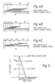
- Figure 4A shows a shingle produced by a conventional slicing machine and jump conveyor when handling the maximum size product that it is set up to produce.
- a log of product of height 48 mm and with four slices per pack and with a pack having an extent in the shingling direction of 76 mm it is desirable to leave a 5 mm border so that the pack can be effectively sealed in a downstream vacuum packaging machine.
- the maximum extent in the shingling direction of the shingle should be 66 mm which, with a 48 mm log height means that the pitch of the shingle should be 6 mm.
- the shingling speed of the jump conveyor is set to produce a pitch of 6 mm for all the packs under these circumstances.
- the present slicing machine includes a sensor 10 which has an arm 11 which engages the top of the log 5 immediately adjacent the blade 3 and produces an output proportional to the height of the log 5.
- This output is used to control the shingle speed so that the shingled pack has a substantially constant length in the shingle direction.
- the control means changes the feed speed to produce a pitch of 13.7 mm between adjacent slices as shown in Figure 4C so that, once again, a shingled length of 66 mm is produced leaving a 5 mm border around the 76 mm long pack.
- Figure 5 is a graph illustrating how the shingling speed varies with the log height to produce packs of constant shingle length.
Landscapes
- Life Sciences & Earth Sciences (AREA)
- Forests & Forestry (AREA)
- Engineering & Computer Science (AREA)
- Mechanical Engineering (AREA)
Abstract
Description
- In slicing foodstuffs a slicing machine is used to cut slices from a block of meat or meat product or a prism of cheese at a constant repetition rate. The cut slices fall onto what is known as a jump conveyor which, typically moves forwards at a slow speed to provide a shingle of slices and then, after a predetermined number of slices or a predetermined weight of foodstuff has been cut, accelerates and travels briefly at high speed. Early examples of jump conveyors such as disclosed in US-A-3910141 also stop the feed of foodstuff towards the blade at this time to allow sufficient time for the "jump" operation to occur to separate one shingled group of slices from the next. However, more recently jump conveyors have been arranged to have a faster jump operation so that the jump operation is carried out entirely in the interval between the cutting of consecutive slices. Such jump conveyors are typically driven from two separate drives, a high speed drive and a low speed drive both of which run continuously. One or other of the drives is clutched to the conveyor to drive the conveyor at low or high speed.
- It is also known to drive a jump conveyor via a hydraulic motor and to throttle the flow through the hydraulic motor to provide the slow speed. Another form of jump conveyor is described in our specification EP-A-0233008. This jump conveyor comprises two separate multi-element strip conveyors which are interleaved with one another. One conveyor runs at slow speed and is located at a fixed position in space whilst the other conveyor runs at high speed and is movable bodily upwards and downwards. Typically both conveyors run continuously and, after the slow speed conveyor has collected the required group of slices the high speed conveyor is moved up rapidly to engage the base of the group of slices and carry it away at high speed. The high speed conveyor is then lowered again so that the following slice falls on the low speed conveyor. EP-A-0233008 also discloses that the slow speed conveyor may be held stationary or even move slowly in the reverse direction to build up a group of slices into a stack.
- Typically a jump conveyor is followed by another conveyor which forms part of a downstream packaging line. In US-A-3910141 this following conveyor runs at a higher speed than the jump conveyor so that the separation between the groups of slices is increased as they are transferred onto the following conveyor.
- A slicing machine capable of high speed operation can cut as many slices as 1200 per minute. It is usually the jump conveyor which provides the limitation on the slicing speed because as the slicing speed of the slicer increases so the time interval between consecutive slices gets shorter and this means that the jump conveyor has less time to separate one group from another. With the jump conveyors described above most slicing machines operate in the region of up to 100 packs per minture and thus 100 shingled groups per minute but with the slicing machine described in EP-A-0233008 we have been able to reach speeds as high as 120 - 140 packs per minute but it is naturally desirable to be able to increase this speed still further.
- According to a first aspect of this invention a combined jump conveyor and slicing machine includes a jump conveyor formed by first short conveyor adjacent the slicing blade of the slicing machine having a length substantially equal to the height capacity of the slicing machine and a second conveyor downstream of the first conveyor, both conveyors of the jump conveyor having an independent drive and control means to drive the two conveyors at the same speed or at different speeds, the independent drive and control means of the first conveyor also enabling it to be driven at high speed in the reverse direction away from the second conveyor to reject slices cut by the slicing blade.
- With the arrangement in accordance with this invention the jump conveyor is formed by two separate conveyors, the first conveyor of which is short having a length which is approximately equal to that of the slices and cut by the slicing machine. When it is required that the slices be formed into groups having the form of a stack the first conveyor is held stationary or moved slowly in the reverse direction away from the second conveyor whilst the stack is accumulated on it. As explained in detail in specification EP-A-0233008 the flight path of the slices after they have been cut and before they land on the jump conveyor is curved and, therefore, to get an aligned stack, as the height of the stack increases the stack is moved closer to the slicing blade. Whilst the first conveyor is carrying out this maneouvre the second conveyor is completely free to move at whatever speed is required, for example to move at the line speed to be able to transfer a preceding stack to a downstream packaging line without distortion. When the slicing machine is forming shingled groups then the first conveyor moves forwards slowly so that the slices are formed into a shingled group on it. Since the first conveyor is only the same length as a single slice the slices of a shingled group are longer than the first conveyor alone. Thus during shingling both the first and second conveyor move at the same slow forwards speed and, in this way, can accommodate a long shingle of slices.
- As soon as the slicing of the group has been completed both the first and second conveyors are moved at high speed in the interval between the slicing of two consecutive slices to create a gap between sucessive groups. As soon as the group has left the first conveyor the first conveyor can again be slowed down, stopped or start moving slowly in the reverse direction so that it is ready to receive the first slice of the following group. Equally, as soon as the end of the group has passed onto the second conveyor the second conveyor can carry on at high speed or can be decelerated to match the line speed so that the sliced group of product is transferred to a downstream packaging line at the line speed of that product. When the jump conveyor is preparing shingled groups of slices the second conveyor slows down to the shingling speed as soon as it has transferred the preceding group so that it can again co-operate with the first conveyor to hold the next shingled group as it is cut.
- The intitial and final slices that are cut from a piece of meat or meat product tend to be irregularly shaped and tend not to be of the correct weight. Our co-pending patent application claiming priority from GB8911522 filed on the same day as this application and incorporated herein by reference describes a product slicing system in which the leading and trailing ends of each log of product are detected and in which the slices cut from the regions adjacent each end are rejected. Preferably such a product slicing system includes a combined slicing machine and jump conveyor in accordance with this invention and the first conveyor is run at high speed in the reverse direction to reject the slices cut from the end region of each log of product. Typically the high speed in the reverse direction is substantially the same speed that the jump conveyor moves to jump in the forwards direction. Acceptable products on the second conveyor are meanwhile transferred to the packaging line.
- Preferably both the first and second conveyors of the jump conveyor have the form of multi-element strip conveyors, the ends of which are, at least to some extent, interleaved to obtain a smooth transfer of the product from the first to the second conveyor of the jump conveyor. Preferably both the first and second conveyors are driven by DC brushless motors which have a very high torque and are controllable to a high degree. In this way the motors, and hence the conveyors can be both accelerated and decelerated rapidly in the interval between the cutting of two consecutive slices by the slicing machine. Preferably the first and second conveyors and the operation of a slicing machine are all under the control of a programmed computer, or a programmed logic controller so that the timing of the speed changes of the first and second conveyor is directly coupled to the operation and slice cutting of the slicing machine.
- When making shingled packs in the past the jump conveyor has a fixed slow shingling speed for each product that it handles. Since meat is a natural product size variations occur between different blocks or logs of product. The fixed shingling speed that is selected is thus determined as being the speed which, with the largest height of product likely to be cut the slices are spread out across the entire pack. However when the slicing machine is cutting a log with a smaller height this same fixed shingling speed does not spread the slices over the entire pack and this can give the impression to the eventual purchaser that the pack is not full even though it is, of course, of the correct weight.
- According to a second aspect of this invention a slicing machine and jump conveyor combination includes a sensor which detects the height of a log to be cut immediately upstream of the slicing blade of the slicer and means to control the low shingling speed of the jump conveyor in accordance with the output of the sensor to provide groups of shingled slices of constant length in the shingling direction.
- The jump conveyor may be one of the conventional types described in the introduction with a variable speed drive but preferably it is of the kind defined in the first aspect of this invention.
- Preferably the control unit calculates the pitch P between adjacent slices of a shingle and hence the shingling speed of the jump conveyor using the following equation:-
P =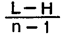
where L is the required total length of the shingled pack, H is the height of the log and n is the number of slices in the pack. - The sensor for detecting the height of each log immediately upstream of the slicing blade may simply be formed by a feeler which engages the upper surface of the log and is connected to an encoder or potentiometer or, alternatively the sensor may be an ultrasonic or laser operated distance measuring device which measures the distance to the upper surface of the log and, from this measurement, derives the height of the log.
- A slicing machine and jump conveyor combination in accordance with the first aspect of this invention is very much more versatile than any of the preceding arrangements since the product only has to clear the first short conveyor in the time interval between the cutting of consecutive slices. This is true whether the short conveyor is operated at high speed in the reverse direction to reject a slice or whether it moves at high speed in the forwards direction to form a separation between the adjacent groups of product. The separate second conveyor can, once decoupled from the first conveyor, then be slowed down to the line speed. We have found it possible to produce packs at speeds as high as 160 per minute with a combination in accordance with the present invention. A slicing machine and jump conveyor combination in accordance with the second aspect of this invention ensures a consistent filling of each pack irrespective of variations in the height of the log being sliced.
- A particular example of a jump conveyor and slicing machine combination in accordance with this invention will now be described with reference to the accompanying drawings, in which:-
- Figure 1 is a diagrammatic view of a slicing machine and jump conveyor combination;
- Figure 2 is a speed diagram showing the speed of the two jump conveyors when forming a pack stack;
- Figure 3 is a speed diagram of the two jump conveyors when forming a shingled pack;
- Figures 4A, B & C are diagrams showing shingled packs; and,
- Figure 5 is a graph illustrating the relationship between feed rate of the jump conveyor and the height of the log.
- A combination in accordance with this invention comprises a jump conveyor formed by a
first conveyor 1 and a second,downstream conveyor 2, arranged to receive slices cut by the slicingblade 3 of a slicing machine indicated generally by reference numeral 4. The slicing machine is conventional in construction and is a standard "Polyslicer" manufactured by Thurne Engineering Company Limited of Delta Close, Norwich, Norfolk. The slicing machine 4 cuts alog 5 of product which is moved forwards, to the left as shown in Figure 1, continuously by a drive, not shown.Slices 6 cut from the face of thelog 5 fall onto the upper surface ofconveyor 1 and substantially fill it. Theconveyors brushless DC motors 7 and 8 and are controlled independently by acontrol unit 9. - Figure 2 illustrates the way in which the speed of the two
conveyors conveyor 2 is shown by a dotted line whilst the speed ofconveyor 1 is shown by a solid line. Once the stack is formed with the required number of slices,conveyors conveyor 1 toconveyor 2 during this period.Conveyor 1 then declerates equally rapidly and returns to the slow speed in the reverse direction.Conveyor 2 is held at the highest speed that is reached for a period to provide a substantial separation of the pack from the following pack and is then slowed down to the speed of the packaging line. The pack is transferred from theconveyor 2 to the packaging line whilst their speeds are matched and then, subsequently, the speed ofconveyor 2 is matched to that ofconveyor 1 and hence moved slowly in the reverse direction. The process is then repeated for the next stack of slices. - All the while that the
first conveyor 1 is operating at a slow speed in the reverse direction it is capable of receivingslices 6 cut by the slicing machine 4 and forming them into stacks, it is only during the short acceleration and deceleration which takes place in the interval between the cutting of two consecutive slices that the first conveyor is operated at a different speed. However, the second conveyor operates at high speed firstly to establish a gap between one stack and another stack of products and secondly is operated at the line speed so that a smooth transfer of product takes place to a downstream packaging line. - When producing a shingle of slices as shown in Figure 3 both
conveyors second conveyor 2 whilst further slices are still being added to thefirst conveyor 1. On completion of the pack, both conveyors are accelerated rapidly as the final slices of the pack are transferred from thefirst conveyor 1 to thesecond conveyor 2. Thefirst conveyor 1 is then decelerated rapidly to return it to the slow forwards shingle speed whilst thesecond conveyor 2 is maintained at high speed to establish a substantial separation between one pack and the next. The second conveyor is then decelerated to line speed to enable the shingled group of slices to be transferred from the second conveyor to a downstream packaging line before returning to the shingling speed to be able to receive the initial slices of the following pack as they are transferred from thefirst conveyor 1 to thesecond conveyor 2. - Figure 4A shows a shingle produced by a conventional slicing machine and jump conveyor when handling the maximum size product that it is set up to produce. With a log of product of
height 48 mm and with four slices per pack and with a pack having an extent in the shingling direction of 76 mm it is desirable to leave a 5 mm border so that the pack can be effectively sealed in a downstream vacuum packaging machine. Accordingly, the maximum extent in the shingling direction of the shingle should be 66 mm which, with a 48 mm log height means that the pitch of the shingle should be 6 mm. In a conventional slicing machine and jump conveyor combination the shingling speed of the jump conveyor is set to produce a pitch of 6 mm for all the packs under these circumstances. However, when the slicing machine and jump conveyor are handling a product having a height of only 25 mm when the same shingling speed is used a pack as shown in Figure 4B is produced with a 5 mm gap at the leading edge but a 28 mm gap at the trailing edge. Such a pack gives the appearance of being only half full to the eventual consumer and this is not preferred. - Accordingly, the present slicing machine includes a
sensor 10 which has anarm 11 which engages the top of thelog 5 immediately adjacent theblade 3 and produces an output proportional to the height of thelog 5. This output is used to control the shingle speed so that the shingled pack has a substantially constant length in the shingle direction. Clearly if the log height is 48 mm then a pack identical to that shown in Figure 4A is produced. However with a log height of 25 mm, as shown in Figure 4B the control means changes the feed speed to produce a pitch of 13.7 mm between adjacent slices as shown in Figure 4C so that, once again, a shingled length of 66 mm is produced leaving a 5 mm border around the 76 mm long pack. Of course this flexibility means that if the log height is unexpectedly greater than 48 mm and so would in a conventional system overlap the 5 mm border and so produce a defective package in the vacuum packaging machine, the pitch is correspondingly reduced below 6 mm again to produce a shingle having a length of only 66 mm. - Figure 5 is a graph illustrating how the shingling speed varies with the log height to produce packs of constant shingle length.
Claims (7)
P =
where L is the required total length of the shingled pack, H is the height of the log and n is the number of slices in the pack.
Applications Claiming Priority (2)
| Application Number | Priority Date | Filing Date | Title |
|---|---|---|---|
| GB8911523 | 1989-05-19 | ||
| GB898911523A GB8911523D0 (en) | 1989-05-19 | 1989-05-19 | Combined jump conveyor and slicing machine |
Publications (2)
| Publication Number | Publication Date |
|---|---|
| EP0398603A1 true EP0398603A1 (en) | 1990-11-22 |
| EP0398603B1 EP0398603B1 (en) | 1994-07-20 |
Family
ID=10657018
Family Applications (1)
| Application Number | Title | Priority Date | Filing Date |
|---|---|---|---|
| EP90305139A Expired - Lifetime EP0398603B1 (en) | 1989-05-19 | 1990-05-14 | Combined jump conveyor and slicing machine |
Country Status (6)
| Country | Link |
|---|---|
| US (1) | US5125303A (en) |
| EP (1) | EP0398603B1 (en) |
| JP (1) | JPH0373294A (en) |
| CA (1) | CA2016903A1 (en) |
| DE (1) | DE69010767T2 (en) |
| GB (1) | GB8911523D0 (en) |
Cited By (8)
| Publication number | Priority date | Publication date | Assignee | Title |
|---|---|---|---|---|
| EP0634325A1 (en) * | 1993-06-09 | 1995-01-18 | Dixie-Union Verpackungen GmbH | Device for arranging sliced products in an overlapping shingle pattern |
| EP0733449A3 (en) * | 1995-03-22 | 1997-01-15 | Ryowa & Co Ltd | Device for dispensing food products |
| WO2000059692A1 (en) * | 1999-03-31 | 2000-10-12 | Biforce Anstalt | Method and device for slicing food products |
| NL1016422C2 (en) * | 2000-10-18 | 2002-04-22 | Sleegers Techniek B V | Slicing machine for foodstuffs, has collection station which contains parallel conveyor belts and can be moved sideways |
| EP0982107A3 (en) * | 1998-08-28 | 2002-12-18 | Weber Maschinenbau GmbH & Co. KG | Method and apparatus for stacking sliced food products |
| WO2005087456A1 (en) * | 2004-02-13 | 2005-09-22 | Cfs Kempten Gmbh | Method and device for producing portions |
| EP1982805A2 (en) | 2007-04-13 | 2008-10-22 | AEW Delford Systems Limited | Food processing apparatus and operation thereof |
| EP1911555A3 (en) * | 2004-02-13 | 2008-12-10 | CFS Kempten GmbH | Method and apparatus for producing portions |
Families Citing this family (19)
| Publication number | Priority date | Publication date | Assignee | Title |
|---|---|---|---|---|
| US5535654A (en) * | 1991-11-28 | 1996-07-16 | Microm Laborgerate Gmbh | Microtome |
| JP3077871B2 (en) * | 1994-04-05 | 2000-08-21 | ジューキ株式会社 | Paper transport device |
| US6073527A (en) * | 1997-04-11 | 2000-06-13 | Marquip, Inc. | Method and apparatus for direct shingling of cut sheets at the cutoff knife |
| GB9827855D0 (en) * | 1998-12-17 | 1999-02-10 | Wright Pugson Limited | Methods and apparatus for cutting cheese |
| US6387653B1 (en) * | 1999-04-09 | 2002-05-14 | Culterra, Llc | Apparatus and method for automatically producing tissue slides |
| DE10109142A1 (en) * | 2001-02-26 | 2002-09-05 | Cfs Gmbh Kempten | Method and device for shingled sliced goods |
| US6763750B2 (en) | 2002-02-07 | 2004-07-20 | Formax, Inc. | Conveyor system for slicer apparatus |
| US6763748B2 (en) * | 2002-07-26 | 2004-07-20 | Formax, Inc. | Automatic draft length compensation for slicing machine system |
| US6935215B2 (en) * | 2002-08-14 | 2005-08-30 | Formax, Inc. | Slicing machine and conveyor system with automatic product width compensation |
| US7698977B2 (en) * | 2004-11-19 | 2010-04-20 | Aew Delford Group Limited | Combined articulated jump conveyor and slicing machine |
| JP4649579B2 (en) * | 2005-02-18 | 2011-03-09 | 株式会社日本キャリア工業 | Meat slicer operation method |
| US8250955B2 (en) * | 2007-10-22 | 2012-08-28 | Formax, Inc. | Food article transfer mechanism for a food article slicing machine |
| NL2017923B1 (en) * | 2016-12-05 | 2018-06-18 | Qimarox Patenten B V | Device and method configured to control rotation of an object on a carrier |
| US11148313B2 (en) | 2018-01-26 | 2021-10-19 | Provisur Technologies, Inc. | Food log slicing apparatus for slicing multiple layers of stacked food logs |
| US11198565B2 (en) | 2019-02-19 | 2021-12-14 | Provisur Technologies, Inc. | Multi-presentation slicing conveyor apparatus |
| DE102020106054B4 (en) | 2020-03-05 | 2025-11-13 | Multivac Sepp Haggenmüller Se & Co. Kg | Methods for producing shingled portions and slicers used for this purpose |
| CA3184507A1 (en) * | 2020-06-02 | 2021-12-09 | Nippon Career Industry Co., Ltd. | Method for producing masses of food pieces and device for producing masses of food pieces |
| JP7590750B2 (en) * | 2020-06-02 | 2024-11-27 | 株式会社日本キャリア工業 | Method and device for forming food piece aggregates |
| JP7511841B2 (en) * | 2020-11-24 | 2024-07-08 | 株式会社日本キャリア工業 | Apparatus for forming food piece aggregates and storage device for use with said apparatus for forming food piece aggregates |
Citations (3)
| Publication number | Priority date | Publication date | Assignee | Title |
|---|---|---|---|---|
| US3910141A (en) * | 1974-08-16 | 1975-10-07 | Cashin Systems Corp | Apparatus for slicing food product and separating drafts of slices |
| AT355446B (en) * | 1977-06-01 | 1980-03-10 | Kuchler Fritz | SLICER |
| GB2139876A (en) * | 1983-05-17 | 1984-11-21 | Amca Int Corp | Method and apparatus for trimming slices from a product |
Family Cites Families (6)
| Publication number | Priority date | Publication date | Assignee | Title |
|---|---|---|---|---|
| US3010499A (en) * | 1956-02-20 | 1961-11-28 | Emhart Mfg Co | Automatic slicing machine for a meat product or the like |
| US3133571A (en) * | 1957-04-04 | 1964-05-19 | Swift & Co | Apparatus for preparing equal weight slices of product |
| US4379416A (en) * | 1977-06-01 | 1983-04-12 | Brain Dust Patents Establishment | Food-slicing machine and method |
| CH659232A5 (en) * | 1983-01-14 | 1987-01-15 | Grapha Holding Ag | DEVICE FOR TURNING SUB-SCALES consisting of PRINTED SHEETS. |
| CH660353A5 (en) * | 1983-05-17 | 1987-04-15 | Grapha Holding Ag | METHOD AND DEVICE FOR DIVIDING A DOMESTIC CURRENT FROM PRINTED SHEETS IN PARTIAL SCALES. |
| GB8314765D0 (en) * | 1983-05-27 | 1983-07-06 | Thurne Eng Co Ltd | Slicing machine |
-
1989
- 1989-05-19 GB GB898911523A patent/GB8911523D0/en active Pending
-
1990
- 1990-05-14 DE DE69010767T patent/DE69010767T2/en not_active Expired - Fee Related
- 1990-05-14 EP EP90305139A patent/EP0398603B1/en not_active Expired - Lifetime
- 1990-05-16 CA CA002016903A patent/CA2016903A1/en not_active Abandoned
- 1990-05-18 JP JP2127044A patent/JPH0373294A/en active Pending
- 1990-05-18 US US07/524,897 patent/US5125303A/en not_active Expired - Lifetime
Patent Citations (3)
| Publication number | Priority date | Publication date | Assignee | Title |
|---|---|---|---|---|
| US3910141A (en) * | 1974-08-16 | 1975-10-07 | Cashin Systems Corp | Apparatus for slicing food product and separating drafts of slices |
| AT355446B (en) * | 1977-06-01 | 1980-03-10 | Kuchler Fritz | SLICER |
| GB2139876A (en) * | 1983-05-17 | 1984-11-21 | Amca Int Corp | Method and apparatus for trimming slices from a product |
Cited By (9)
| Publication number | Priority date | Publication date | Assignee | Title |
|---|---|---|---|---|
| EP0634325A1 (en) * | 1993-06-09 | 1995-01-18 | Dixie-Union Verpackungen GmbH | Device for arranging sliced products in an overlapping shingle pattern |
| EP0733449A3 (en) * | 1995-03-22 | 1997-01-15 | Ryowa & Co Ltd | Device for dispensing food products |
| EP0982107A3 (en) * | 1998-08-28 | 2002-12-18 | Weber Maschinenbau GmbH & Co. KG | Method and apparatus for stacking sliced food products |
| WO2000059692A1 (en) * | 1999-03-31 | 2000-10-12 | Biforce Anstalt | Method and device for slicing food products |
| US6640681B1 (en) | 1999-03-31 | 2003-11-04 | Weber Maschinenbau Gmbh Co. Kg | Method and device for slicing food products |
| NL1016422C2 (en) * | 2000-10-18 | 2002-04-22 | Sleegers Techniek B V | Slicing machine for foodstuffs, has collection station which contains parallel conveyor belts and can be moved sideways |
| WO2005087456A1 (en) * | 2004-02-13 | 2005-09-22 | Cfs Kempten Gmbh | Method and device for producing portions |
| EP1911555A3 (en) * | 2004-02-13 | 2008-12-10 | CFS Kempten GmbH | Method and apparatus for producing portions |
| EP1982805A2 (en) | 2007-04-13 | 2008-10-22 | AEW Delford Systems Limited | Food processing apparatus and operation thereof |
Also Published As
| Publication number | Publication date |
|---|---|
| GB8911523D0 (en) | 1989-07-05 |
| EP0398603B1 (en) | 1994-07-20 |
| US5125303A (en) | 1992-06-30 |
| DE69010767D1 (en) | 1994-08-25 |
| JPH0373294A (en) | 1991-03-28 |
| CA2016903A1 (en) | 1990-11-19 |
| DE69010767T2 (en) | 1994-10-27 |
Similar Documents
| Publication | Publication Date | Title |
|---|---|---|
| EP0398603B1 (en) | Combined jump conveyor and slicing machine | |
| US5566600A (en) | Conveyor/classifier system for versatile hi-speed food loaf slicing machine | |
| US5724874A (en) | Method of manufacturing food loaf slice groups | |
| US5628237A (en) | Slicing machine for two or more food loaves | |
| EP0907472B1 (en) | Slicing of products | |
| US5787776A (en) | Food slicer | |
| CA1112099A (en) | Processor-stacker for papered food patties and like layered objects | |
| US20020059858A1 (en) | Improved slicing blade for concurrently slicing a plurality of product loaves disposed in a side- by -side relationship | |
| US5101702A (en) | Slicing machine with alternate-slice stacker | |
| JP2000288983A (en) | Raw slicing equipment for food such as ham | |
| EP0504466B1 (en) | Cutting apparatus and process | |
| KR20110136808A (en) | Method and device for creating a formatted package | |
| US6152004A (en) | Apparatus for forming stacks | |
| EP0591005B1 (en) | Automated line and method for preparing premade food set-ups | |
| JP2519028B2 (en) | Sheet transfer device | |
| US6938393B2 (en) | Packaging line and method for packaging separate products in a continuous manner | |
| JP2935526B2 (en) | Separation equipment for unbound stacking | |
| JPS63232996A (en) | Movable stacker in food slicing machine | |
| US20240342942A1 (en) | Cutting device for slicing foodstuffs and associated operating method | |
| US7698977B2 (en) | Combined articulated jump conveyor and slicing machine | |
| US20240083060A1 (en) | System and operating method for packaging paper rolls | |
| EP0830068B1 (en) | An indexer for moving food along a processing line in a precise manner | |
| US20060042434A1 (en) | Method and apparatus for slicing a block of material | |
| US20040118085A1 (en) | Apparatus for and method of transporting and stacking groups of flat articles and moving the group stacks to another location | |
| JPH0740284A (en) | Measuring slicer |
Legal Events
| Date | Code | Title | Description |
|---|---|---|---|
| PUAI | Public reference made under article 153(3) epc to a published international application that has entered the european phase |
Free format text: ORIGINAL CODE: 0009012 |
|
| AK | Designated contracting states |
Kind code of ref document: A1 Designated state(s): DE FR GB IT SE |
|
| 17P | Request for examination filed |
Effective date: 19901214 |
|
| 17Q | First examination report despatched |
Effective date: 19920904 |
|
| GRAA | (expected) grant |
Free format text: ORIGINAL CODE: 0009210 |
|
| AK | Designated contracting states |
Kind code of ref document: B1 Designated state(s): DE FR GB IT SE |
|
| PG25 | Lapsed in a contracting state [announced via postgrant information from national office to epo] |
Ref country code: IT Free format text: LAPSE BECAUSE OF FAILURE TO SUBMIT A TRANSLATION OF THE DESCRIPTION OR TO PAY THE FEE WITHIN THE PRE;WARNING: LAPSES OF ITALIAN PATENTS WITH EFFECTIVE DATE BEFORE 2007 MAY HAVE OCCURRED AT ANY TIME BEFORE 2007. THE CORRECT EFFECTIVE DATE MAY BE DIFFERENT FROM THE ONE RECORDED.SCRIBED TIME-LIMIT Effective date: 19940720 Ref country code: FR Effective date: 19940720 |
|
| REF | Corresponds to: |
Ref document number: 69010767 Country of ref document: DE Date of ref document: 19940825 |
|
| PG25 | Lapsed in a contracting state [announced via postgrant information from national office to epo] |
Ref country code: SE Effective date: 19941020 |
|
| EN | Fr: translation not filed | ||
| PLBI | Opposition filed |
Free format text: ORIGINAL CODE: 0009260 |
|
| 26 | Opposition filed |
Opponent name: FIRMA WEBER MASCHINENBAU GMBH Effective date: 19950418 |
|
| PLBO | Opposition rejected |
Free format text: ORIGINAL CODE: EPIDOS REJO |
|
| APAC | Appeal dossier modified |
Free format text: ORIGINAL CODE: EPIDOS NOAPO |
|
| APAE | Appeal reference modified |
Free format text: ORIGINAL CODE: EPIDOS REFNO |
|
| APAC | Appeal dossier modified |
Free format text: ORIGINAL CODE: EPIDOS NOAPO |
|
| APAE | Appeal reference modified |
Free format text: ORIGINAL CODE: EPIDOS REFNO |
|
| APAC | Appeal dossier modified |
Free format text: ORIGINAL CODE: EPIDOS NOAPO |
|
| REG | Reference to a national code |
Ref country code: GB Ref legal event code: IF02 |
|
| PLBN | Opposition rejected |
Free format text: ORIGINAL CODE: 0009273 |
|
| STAA | Information on the status of an ep patent application or granted ep patent |
Free format text: STATUS: OPPOSITION REJECTED |
|
| 27O | Opposition rejected |
Effective date: 20011106 |
|
| APAH | Appeal reference modified |
Free format text: ORIGINAL CODE: EPIDOSCREFNO |
|
| REG | Reference to a national code |
Ref country code: GB Ref legal event code: 732E |
|
| PLAB | Opposition data, opponent's data or that of the opponent's representative modified |
Free format text: ORIGINAL CODE: 0009299OPPO |
|
| PGFP | Annual fee paid to national office [announced via postgrant information from national office to epo] |
Ref country code: DE Payment date: 20080522 Year of fee payment: 19 |
|
| PGFP | Annual fee paid to national office [announced via postgrant information from national office to epo] |
Ref country code: GB Payment date: 20080514 Year of fee payment: 19 |
|
| GBPC | Gb: european patent ceased through non-payment of renewal fee |
Effective date: 20090514 |
|
| PG25 | Lapsed in a contracting state [announced via postgrant information from national office to epo] |
Ref country code: GB Free format text: LAPSE BECAUSE OF NON-PAYMENT OF DUE FEES Effective date: 20090514 |
|
| PG25 | Lapsed in a contracting state [announced via postgrant information from national office to epo] |
Ref country code: DE Free format text: LAPSE BECAUSE OF NON-PAYMENT OF DUE FEES Effective date: 20091201 |