EP0399130A1 - Shutters with tiltable louver boards - Google Patents
Shutters with tiltable louver boards Download PDFInfo
- Publication number
- EP0399130A1 EP0399130A1 EP89830226A EP89830226A EP0399130A1 EP 0399130 A1 EP0399130 A1 EP 0399130A1 EP 89830226 A EP89830226 A EP 89830226A EP 89830226 A EP89830226 A EP 89830226A EP 0399130 A1 EP0399130 A1 EP 0399130A1
- Authority
- EP
- European Patent Office
- Prior art keywords
- louver
- shutter
- fact
- louver boards
- boards
- Prior art date
- Legal status (The legal status is an assumption and is not a legal conclusion. Google has not performed a legal analysis and makes no representation as to the accuracy of the status listed.)
- Granted
Links
- 238000007789 sealing Methods 0.000 claims description 2
- 239000000463 material Substances 0.000 description 6
- 239000002184 metal Substances 0.000 description 5
- 239000003795 chemical substances by application Substances 0.000 description 3
- 230000033001 locomotion Effects 0.000 description 3
- 238000004519 manufacturing process Methods 0.000 description 2
- 239000004033 plastic Substances 0.000 description 2
- 239000002023 wood Substances 0.000 description 2
- 230000005540 biological transmission Effects 0.000 description 1
- 230000000903 blocking effect Effects 0.000 description 1
- 230000002427 irreversible effect Effects 0.000 description 1
- 230000000414 obstructive effect Effects 0.000 description 1
- 230000000717 retained effect Effects 0.000 description 1
- 239000007787 solid Substances 0.000 description 1
- 229910001220 stainless steel Inorganic materials 0.000 description 1
Images


Classifications
-
- E—FIXED CONSTRUCTIONS
- E06—DOORS, WINDOWS, SHUTTERS, OR ROLLER BLINDS IN GENERAL; LADDERS
- E06B—FIXED OR MOVABLE CLOSURES FOR OPENINGS IN BUILDINGS, VEHICLES, FENCES OR LIKE ENCLOSURES IN GENERAL, e.g. DOORS, WINDOWS, BLINDS, GATES
- E06B7/00—Special arrangements or measures in connection with doors or windows
- E06B7/02—Special arrangements or measures in connection with doors or windows for providing ventilation, e.g. through double windows; Arrangement of ventilation roses
- E06B7/08—Louvre doors, windows or grilles
- E06B7/084—Louvre doors, windows or grilles with rotatable lamellae
- E06B7/086—Louvre doors, windows or grilles with rotatable lamellae interconnected for concurrent movement
-
- E—FIXED CONSTRUCTIONS
- E06—DOORS, WINDOWS, SHUTTERS, OR ROLLER BLINDS IN GENERAL; LADDERS
- E06B—FIXED OR MOVABLE CLOSURES FOR OPENINGS IN BUILDINGS, VEHICLES, FENCES OR LIKE ENCLOSURES IN GENERAL, e.g. DOORS, WINDOWS, BLINDS, GATES
- E06B7/00—Special arrangements or measures in connection with doors or windows
- E06B7/02—Special arrangements or measures in connection with doors or windows for providing ventilation, e.g. through double windows; Arrangement of ventilation roses
- E06B7/08—Louvre doors, windows or grilles
- E06B7/084—Louvre doors, windows or grilles with rotatable lamellae
- E06B7/086—Louvre doors, windows or grilles with rotatable lamellae interconnected for concurrent movement
- E06B7/096—Louvre doors, windows or grilles with rotatable lamellae interconnected for concurrent movement operated or interconnected by gearing
Definitions
- the object of the present invention is an improvement of the tiltable louver-board shutters.
- the classic shutter has been preferred again that is a shutter with louver boards made of various materials such as wood, metal and plastic materials and disposed horizontally in parallel rows either fixed or tiltable.
- the purpose of this invention is to realize a tiltable louver board which prevents the above drawbacks exhibits and modular shape and size requirements, components standardization, ready mounting with no use of any tool and the chance of having a manual, motorized or automatic control, possibly associated with a photoelectric cell, so that the tilting of the louver boards can be put at the best as a function of the outside weather conditions.
- a shutter provided with tiltable louver boards comprises modular elements fitted in a frame made of standard sections, said modular elements comprising a pair of parallel racks with which a plurality of pinious or gears is engaged which are fastened to a corresponding number of head supports of the louver boards of the shutter, each of said rack modular elements being provided with a longitudinal slot which extends for a large portion of the same module length and is intended for allowing the transverse sliding connection between the racks and the passage of a rod for controlling the louver boards which is keyed on one of said pinions, whereby a self-locking is made which can be mounted at any spot along the sides of the shutter.
- Said modular rack-elements are provided at their ends with male and female junctions whereby two or more rack elements can be restrain-jointed in prosecution as far as the desired length is obtained.
- the shutters according to this invention comprises a perimetrical frame made of metal or other suitable material such as for instance a metal standard section made of two cross members 1 respectively located at the base and at the top and of two upright side-struts 2.
- Elements 1 and 2 are provided with usual cuts 3 at 45 degrees at the corners and are connected to one another by means of miter squares 4 cooperating with screws 5 and bores 6 which are provided through the same cross members.
- the two cross members 1 are provided with slot-seats 7 into which the base of a ledge 8,8′ is retained at its ends by terminal blocks 9 housed in upright sides 2 of the frame.
- gaskets 10 In ledges 8,8′ are fitted gaskets 10 by which a perfect seal is ensured against light and weather agents whenever the adjacent louvers of the shutter are in a closure attitude.
- an analogous gasket 10 is inserted along one of the edges of the louver boards 11 which in Fig. 1 are shown as tubular elements made of tubular metal thin sheet or plastic material or other suitable material.
- racks 12 which are formed by two modular elements of which one carries at its upper end a toothed projection 13 and at its lower end a recess 14 while the other carries at its upper end a recess 14 and at its lower end a toothed projection 13 which projections and recesses allow to obtain rapidly and without any tool the required height of the shutter.
- each modular element 12 of a rack is provided with a large slot 15 which extends substantially for all the length of the modular element 12.
- some supporting plates 16 are provided at intervals which have a circular bore 17 and four chamfered stakes 18, located at the corners of said plates, which stakes, being inserted through slots 15, allow to keep said racks at their positions with the rack teeth 19 facing each other.
- pinions 20 are inserted which are engaged with the rack teeth and are disposed at intervals equal to the distances between the axes of two subsequent louver boards.
- Each pinion 20 is provided at its center with a "thousand grooves" bore in which a corresponding hub 22 is inserted which is carried by the head-support 23 on which a louver board 11 is fitted.
- Head support 23 at the portion thereof adjoining upright side 2 has a bent edge 24 (fig. 4). Between head support 23 and hub 22 a flexible strip 25 is inserted which penetrates between the longitudinal edges 26 of standard section upright side 2 and which is pushed towards the head-support 23 by means of a spring 27 made of inox steel coaxial with pinion 20. Whenever the louver board is in opened position (Fig. 4) the bent edge 24 of bent edge 24 of support 23 urges spring 27 to compress whereby flexible strip 25 is urged between the edges 26 of standard section upright side 2.
- spring 27 urges flexible strip 25 against the head-support 23 thereby ensuring the perfect seal against light and weather agents coming from above.
- said seal is ensured by the above gaskets 10 which are arranged along the edge of each louver board 11.
- a box 30 which is fitted through slot 15 of rack 12 and comprises a circular housing 31 similar to the one carried by guiding support plates 16 (fig. 5) in which one of the pinions 20 is fitted.
- a housing 36 is provided for a worm screw 32 engaged with pinion 20 and secured to a metal axle 33 with exagonal cross section of which an end is fitted into a ferrule 34 while the other end is secured to a crank 35 which is carried by plate 37 fastened to box 30 by means of a pair of screws or other similar means.
- louver boards can be controlled from any spot along the upright side-strut and that said control is totally contained within said side-strut differently from what occurs in the shutters of the present trade.
- crank control has been represented and described but it should be understood that a motorized control can also be provided which could be possibly automatized by a fotoelectric cell device which could be actuated by outside light.
Landscapes
- Engineering & Computer Science (AREA)
- Civil Engineering (AREA)
- Structural Engineering (AREA)
- Blinds (AREA)
- Specific Sealing Or Ventilating Devices For Doors And Windows (AREA)
- Cooling, Air Intake And Gas Exhaust, And Fuel Tank Arrangements In Propulsion Units (AREA)
- Operating, Guiding And Securing Of Roll- Type Closing Members (AREA)
- Wing Frames And Configurations (AREA)
Abstract
Description
- The object of the present invention is an improvement of the tiltable louver-board shutters.
- During the past half-century, the conventional shutters with fixed louver-boards, downwards inclined and mainly made of wood, have been replaced firstly by windable roller- blinds which while not being the best solution in the matter of window blinds for buildings, have been very popular due to their seeming cheapness and to their practicalness disappearing when opened.
- At relatively recent times, due to reasons depending on the energy crysis and for structural functional and aesthetic considerations the classic shutter has been preferred again that is a shutter with louver boards made of various materials such as wood, metal and plastic materials and disposed horizontally in parallel rows either fixed or tiltable.
- In the recent years the request for tiltable louver boards has remarkably increased and at the same time, the designers and builders have directed their attention to a shutter provided with tiltable louver boards in which the control of the boards tilt is embodied into the periferyframe of the shutter.
- Various attempts have been implemented and proposed for solving this problem. For instance the USA Patent Number 2.610.371 granted in date 16-9-1952 to Daniel I. Hite provides a tilting device of the louver boards which uses a pair of parallel racks vertically disposed which engage a series of pinions connected with the boards. A crank control located outside of the window frame causes the respective sliding of said racks and consequently the tilting of the boards abount their longitudinal axes. The racks comprise sturdy and solid rods, of which the lengths are cut to fit the particular size of the window whereby the control device is rather obstructive and complicated and has an obliged position. Other solutions have been also proposed which however imply mechanical complications, scarcely reliable operation and remarkable obstruction.
- Summing up the above mentioned shutters presently on the trade, suffer from the following limitations.
- I. Lack of good sealing capacity against light and rain and wind both horizontally, particularly at the edges of the boards and vertically particularly at the ends of the boards with regard to the upright sides of the frame.
- II. Unstable louver boards and lack of self-locking of the said boards.
- III. The tilting of the board is not ample enough, the rotation thereof being at the maximum 90 deg.
- IV. The shutters can not be disposed as shutters with fixed louver boards and the latter cannot be used in a vertical attitude for sunlight shut- offs and at the same time cannot be tiltable.
- V. Automatic control systems for tilting the boards cannot be applied.
- VI. The manufacture of a modular productions readily adaptable to satisfy the customer dimensional requirements, with particular reference the shutter height and the location of one or more control spots of the louver movement cannot be made.
- The purpose of this invention is to realize a tiltable louver board which prevents the above drawbacks exhibits and modular shape and size requirements, components standardization, ready mounting with no use of any tool and the chance of having a manual, motorized or automatic control, possibly associated with a photoelectric cell, so that the tilting of the louver boards can be put at the best as a function of the outside weather conditions.
- According to this invention, a shutter provided with tiltable louver boards comprises modular elements fitted in a frame made of standard sections, said modular elements comprising a pair of parallel racks with which a plurality of pinious or gears is engaged which are fastened to a corresponding number of head supports of the louver boards of the shutter, each of said rack modular elements being provided with a longitudinal slot which extends for a large portion of the same module length and is intended for allowing the transverse sliding connection between the racks and the passage of a rod for controlling the louver boards which is keyed on one of said pinions, whereby a self-locking is made which can be mounted at any spot along the sides of the shutter.
- Said modular rack-elements are provided at their ends with male and female junctions whereby two or more rack elements can be restrain-jointed in prosecution as far as the desired length is obtained.
- This invention will be now described with reference to the annexed drawings which show as an illustration and not as a limitation a preferred embodiment thereof.
- In the drawings:
- Fig.1 shows an exploded view of the shutter according to this invention;
- Fig.2 shows a cross section along to a horizontal plane on which the tilting axis of a louver board lies;
- Fig.3 shows a cross section of an upright side-strut of the shutter wherein the louver boards are set in closed positions;
- Fig.4 shows a view similar to Fig. 3 the louver boards being set at the utmost opening;
- Fig.5 shows a vertical cross section in enlarged scale wherein the transverse sliding connection is shown between the two racks;
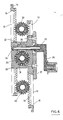
- Fig.6 shows a view similar to Fig. 5 wherein the crank control is shown for tilting the louver boards.
- With reference to Fig. 1 the shutters according to this invention comprises a perimetrical frame made of metal or other suitable material such as for instance a metal standard section made of two cross members 1 respectively located at the base and at the top and of two upright side-
struts 2. -
Elements 1 and 2 are provided withusual cuts 3 at 45 degrees at the corners and are connected to one another by means ofmiter squares 4 cooperating withscrews 5 andbores 6 which are provided through the same cross members. - The two cross members 1 are provided with slot-
seats 7 into which the base of a ledge 8,8′ is retained at its ends byterminal blocks 9 housed inupright sides 2 of the frame. In ledges 8,8′ are fittedgaskets 10 by which a perfect seal is ensured against light and weather agents whenever the adjacent louvers of the shutter are in a closure attitude. For the same purpose ananalogous gasket 10 is inserted along one of the edges of thelouver boards 11 which in Fig. 1 are shown as tubular elements made of tubular metal thin sheet or plastic material or other suitable material. - At the inside of upright sides 2 (see also figures 2-5) are inserted
racks 12 which are formed by two modular elements of which one carries at its upper end atoothed projection 13 and at its lower end arecess 14 while the other carries at its upper end arecess 14 and at its lower end atoothed projection 13 which projections and recesses allow to obtain rapidly and without any tool the required height of the shutter. - As better shown in fig. 5 each
modular element 12 of a rack is provided with alarge slot 15 which extends substantially for all the length of themodular element 12. In order to keep connected with one another the two racks and at the same time to allow the same sliding with reciprocating motion, some supportingplates 16 are provided at intervals which have acircular bore 17 and fourchamfered stakes 18, located at the corners of said plates, which stakes, being inserted throughslots 15, allow to keep said racks at their positions with therack teeth 19 facing each other. Between the teeth of the respective racks,pinions 20 are inserted which are engaged with the rack teeth and are disposed at intervals equal to the distances between the axes of two subsequent louver boards. - In the case of fig. 5 there are three pinions of which one is inserted into
bore 17 of guiding-support plate 16. - Each
pinion 20 is provided at its center with a "thousand grooves" bore in which acorresponding hub 22 is inserted which is carried by the head-support 23 on which alouver board 11 is fitted. - Head support 23 at the portion thereof adjoining
upright side 2 has a bent edge 24 (fig. 4). Betweenhead support 23 and hub 22 aflexible strip 25 is inserted which penetrates between thelongitudinal edges 26 of standard sectionupright side 2 and which is pushed towards the head-support 23 by means of aspring 27 made of inox steel coaxial withpinion 20. Whenever the louver board is in opened position (Fig. 4) thebent edge 24 ofbent edge 24 ofsupport 23urges spring 27 to compress wherebyflexible strip 25 is urged between theedges 26 of standard sectionupright side 2. - In a position of total closure (fig. 2 and 3)
spring 27 urgesflexible strip 25 against the head-support 23 thereby ensuring the perfect seal against light and weather agents coming from above. In case of an horizontal origin of said light and agents, said seal is ensured by theabove gaskets 10 which are arranged along the edge of eachlouver board 11. - As previously mentioned, all the assembly of
racks 12 and of the components thereto associated is readily mounted by fitting it inupright side 2. Thestop stake 28 carried byhub 22 and projecting through a corresponding hole provided in the standard sectionupright side 2 serves for blocking all the assembly at its position and for preventing any accidental slidings. - In fig. 6 the rotation control of the louver boards is illustrated. It consists of a
box 30 which is fitted throughslot 15 ofrack 12 and comprises acircular housing 31 similar to the one carried by guiding support plates 16 (fig. 5) in which one of thepinions 20 is fitted. Still in box 30 ahousing 36 is provided for aworm screw 32 engaged withpinion 20 and secured to ametal axle 33 with exagonal cross section of which an end is fitted into aferrule 34 while the other end is secured to acrank 35 which is carried byplate 37 fastened tobox 30 by means of a pair of screws or other similar means. - Obviously, by turning the crank in the two directions, the corresponding rotation of
pinions 20 and oflouver boards 11 is caused, whereby said boards can make a rotation through an angle of about 180 deg which, from a position of total closure, ranges to a horizontal position (maximum opening) by passing through the various intermediate positions which can be inclined either upwards and downwards. Said rotation movement of the louver boards is impressed by the couple worm screw and pinion which being a transmission of irreversible type contributes to the louver boards the appreciable characteristic of being self-locking and consequently burglar-proof when they are made with material of suitable resistance. - It is to be emphasized also the fact that the rotation of louver boards can be controlled from any spot along the upright side-strut and that said control is totally contained within said side-strut differently from what occurs in the shutters of the present trade.
- For the sake of simplicity a crank control has been represented and described but it should be understood that a motorized control can also be provided which could be possibly automatized by a fotoelectric cell device which could be actuated by outside light.
- The present invention has been illustrated and described with reference to a preferred embodiment thereof but it should be understood that structural variants thereof could be contributed thereto without departing from the protecting scope of the present invention patent.
Claims (12)
Priority Applications (1)
| Application Number | Priority Date | Filing Date | Title |
|---|---|---|---|
| AT89830226T ATE93927T1 (en) | 1988-05-23 | 1989-05-22 | BLINDS WITH SWIVELING BLINDS PANELS. |
Applications Claiming Priority (2)
| Application Number | Priority Date | Filing Date | Title |
|---|---|---|---|
| IT48004/88A IT1219943B (en) | 1988-05-23 | 1988-05-23 | IMPROVEMENT IN ADJUSTABLE SLAT SHUTTERS |
| IT4800488 | 1988-05-23 |
Publications (2)
| Publication Number | Publication Date |
|---|---|
| EP0399130A1 true EP0399130A1 (en) | 1990-11-28 |
| EP0399130B1 EP0399130B1 (en) | 1993-09-01 |
Family
ID=11263909
Family Applications (1)
| Application Number | Title | Priority Date | Filing Date |
|---|---|---|---|
| EP89830226A Expired - Lifetime EP0399130B1 (en) | 1988-05-23 | 1989-05-22 | Shutters with tiltable louver boards |
Country Status (5)
| Country | Link |
|---|---|
| EP (1) | EP0399130B1 (en) |
| AT (1) | ATE93927T1 (en) |
| DE (1) | DE68908877D1 (en) |
| ES (1) | ES2045551T3 (en) |
| IT (1) | IT1219943B (en) |
Cited By (15)
| Publication number | Priority date | Publication date | Assignee | Title |
|---|---|---|---|---|
| ES2064272A2 (en) * | 1992-03-18 | 1995-01-16 | Kikau Srl | Universal persiana reinforcable with vasculating lamps. (Machine-translation by Google Translate, not legally binding) |
| DE29714982U1 (en) * | 1997-08-21 | 1997-12-18 | Sobek, Andrea, 68519 Viernheim | Folding shutter |
| FR2755996A1 (en) * | 1996-11-15 | 1998-05-22 | Lutz Roland | DEVICE FOR HANDLING ASSISTED EFFORT LAMPS |
| US7124537B2 (en) * | 2003-04-11 | 2006-10-24 | Young Stephen C | Decorative shutter with hidden louver control |
| EP1712722A3 (en) * | 2005-04-06 | 2007-01-03 | Lougra, S.L. | Window opening and closing device |
| CN101571411B (en) * | 2009-06-08 | 2010-11-03 | 北京航空航天大学 | Petal-shaped baffle plate observation window mechanism |
| EP2514909A2 (en) | 2011-04-21 | 2012-10-24 | Thomas Fieger | Louvre window |
| US20130086843A1 (en) * | 2010-06-22 | 2013-04-11 | Kee Han Baek | Louver module and louver system employing the same |
| AU2013204717B2 (en) * | 2001-11-30 | 2015-04-30 | Breezway Australia (Holdings) Pty Ltd | A Louvre System |
| ITUA20162363A1 (en) * | 2016-04-07 | 2017-10-07 | Naldo Rotili | System for moving a plurality of fins of a shutter. |
| GB2559269A (en) * | 2016-12-28 | 2018-08-01 | Hunter Douglas | Motorized shutter assembly |
| CN108590475A (en) * | 2018-06-08 | 2018-09-28 | 清远市首建筑新材料有限公司 | A kind of all-sealed shutter |
| EP3816363A1 (en) | 2019-10-31 | 2021-05-05 | Christian Mick | Connecting profile strip |
| JP2023108950A (en) * | 2022-01-26 | 2023-08-07 | 積水ハウス株式会社 | Exterior wall structure |
| GB2588705B (en) * | 2019-07-26 | 2023-10-11 | Hunter Douglas | Shutter panel with an automatic louver closure assembly and related damping features |
Families Citing this family (3)
| Publication number | Priority date | Publication date | Assignee | Title |
|---|---|---|---|---|
| WO2002052119A1 (en) * | 2000-12-22 | 2002-07-04 | Robert Phillip Griffiths | Boss and shutter assembly |
| US20070204513A1 (en) * | 2004-06-17 | 2007-09-06 | Griffiths Robert P | Cassette for Rotating a Louvre Shutter |
| WO2007048175A1 (en) * | 2005-10-24 | 2007-05-03 | Montage Group Pty Ltd | Louvre window system |
Citations (5)
| Publication number | Priority date | Publication date | Assignee | Title |
|---|---|---|---|---|
| US2607585A (en) * | 1950-10-31 | 1952-08-19 | Edward Y Hashimoto | Window structure and operating medium therefor |
| US2610371A (en) * | 1950-02-27 | 1952-09-16 | Daniel I Hite | Shutter structure |
| FR1492403A (en) * | 1966-08-17 | 1967-08-18 | Beta Aluminium Products Ltd | Refinements to slatted windows |
| EP0119369B1 (en) * | 1983-03-10 | 1987-02-25 | FUTURA ALUMINIUM SYSTEMS S.r.l. | Metallic blind formed by assemblable components |
| EP0220355A1 (en) * | 1985-10-30 | 1987-05-06 | KIKAU S.r.l. | Shutter |
-
1988
- 1988-05-23 IT IT48004/88A patent/IT1219943B/en active
-
1989
- 1989-05-22 ES ES89830226T patent/ES2045551T3/en not_active Expired - Lifetime
- 1989-05-22 EP EP89830226A patent/EP0399130B1/en not_active Expired - Lifetime
- 1989-05-22 AT AT89830226T patent/ATE93927T1/en not_active IP Right Cessation
- 1989-05-22 DE DE89830226T patent/DE68908877D1/en not_active Expired - Lifetime
Patent Citations (5)
| Publication number | Priority date | Publication date | Assignee | Title |
|---|---|---|---|---|
| US2610371A (en) * | 1950-02-27 | 1952-09-16 | Daniel I Hite | Shutter structure |
| US2607585A (en) * | 1950-10-31 | 1952-08-19 | Edward Y Hashimoto | Window structure and operating medium therefor |
| FR1492403A (en) * | 1966-08-17 | 1967-08-18 | Beta Aluminium Products Ltd | Refinements to slatted windows |
| EP0119369B1 (en) * | 1983-03-10 | 1987-02-25 | FUTURA ALUMINIUM SYSTEMS S.r.l. | Metallic blind formed by assemblable components |
| EP0220355A1 (en) * | 1985-10-30 | 1987-05-06 | KIKAU S.r.l. | Shutter |
Cited By (26)
| Publication number | Priority date | Publication date | Assignee | Title |
|---|---|---|---|---|
| ES2064272A2 (en) * | 1992-03-18 | 1995-01-16 | Kikau Srl | Universal persiana reinforcable with vasculating lamps. (Machine-translation by Google Translate, not legally binding) |
| FR2755996A1 (en) * | 1996-11-15 | 1998-05-22 | Lutz Roland | DEVICE FOR HANDLING ASSISTED EFFORT LAMPS |
| WO1998022688A1 (en) * | 1996-11-15 | 1998-05-28 | Roland Lutz | Control device for blinds with assisted force |
| DE29714982U1 (en) * | 1997-08-21 | 1997-12-18 | Sobek, Andrea, 68519 Viernheim | Folding shutter |
| AU2013204717B2 (en) * | 2001-11-30 | 2015-04-30 | Breezway Australia (Holdings) Pty Ltd | A Louvre System |
| US7124537B2 (en) * | 2003-04-11 | 2006-10-24 | Young Stephen C | Decorative shutter with hidden louver control |
| EP1712722A3 (en) * | 2005-04-06 | 2007-01-03 | Lougra, S.L. | Window opening and closing device |
| CN101571411B (en) * | 2009-06-08 | 2010-11-03 | 北京航空航天大学 | Petal-shaped baffle plate observation window mechanism |
| US20130086843A1 (en) * | 2010-06-22 | 2013-04-11 | Kee Han Baek | Louver module and louver system employing the same |
| US8826593B2 (en) * | 2010-06-22 | 2014-09-09 | Bautek Co., Ltd. | Louver module and louver system employing the same |
| DE102011018428A1 (en) | 2011-04-21 | 2012-10-25 | Thomas Fieger | Louvre window |
| EP2514909A3 (en) * | 2011-04-21 | 2015-01-21 | Thomas Fieger | Louvre window |
| EP2514909A2 (en) | 2011-04-21 | 2012-10-24 | Thomas Fieger | Louvre window |
| ITUA20162363A1 (en) * | 2016-04-07 | 2017-10-07 | Naldo Rotili | System for moving a plurality of fins of a shutter. |
| US10407977B2 (en) | 2016-12-28 | 2019-09-10 | Hunter Douglas Inc. | Motorized shutter assembly |
| GB2559269A (en) * | 2016-12-28 | 2018-08-01 | Hunter Douglas | Motorized shutter assembly |
| US10697232B2 (en) | 2016-12-28 | 2020-06-30 | Hunter Douglas Inc. | Motorized shutter assembly |
| US11015385B2 (en) | 2016-12-28 | 2021-05-25 | Hunter Douglas Inc. | Motorized shutter assembly |
| GB2559269B (en) * | 2016-12-28 | 2021-09-08 | Hunter Douglas | Motorized shutter assembly |
| CN108590475A (en) * | 2018-06-08 | 2018-09-28 | 清远市首建筑新材料有限公司 | A kind of all-sealed shutter |
| GB2588705B (en) * | 2019-07-26 | 2023-10-11 | Hunter Douglas | Shutter panel with an automatic louver closure assembly and related damping features |
| GB2619632A (en) * | 2019-07-26 | 2023-12-13 | Hunter Douglas | Shutter panel with an automatic louver closure assembly and related damping features |
| GB2619632B (en) * | 2019-07-26 | 2024-03-06 | Hunter Douglas | Shutter panel with an automatic louver closure assembly and related damping features |
| US12188296B2 (en) | 2019-07-26 | 2025-01-07 | Hunter Douglas Inc. | Shutter panel with an automatic louver closure assembly and related damping features |
| EP3816363A1 (en) | 2019-10-31 | 2021-05-05 | Christian Mick | Connecting profile strip |
| JP2023108950A (en) * | 2022-01-26 | 2023-08-07 | 積水ハウス株式会社 | Exterior wall structure |
Also Published As
| Publication number | Publication date |
|---|---|
| DE68908877D1 (en) | 1993-10-07 |
| ES2045551T3 (en) | 1994-01-16 |
| ATE93927T1 (en) | 1993-09-15 |
| EP0399130B1 (en) | 1993-09-01 |
| IT8848004A0 (en) | 1988-05-23 |
| IT1219943B (en) | 1990-05-24 |
Similar Documents
| Publication | Publication Date | Title |
|---|---|---|
| EP0399130B1 (en) | Shutters with tiltable louver boards | |
| US5540018A (en) | Integrated window construction system for mounting both window systems and hurricane protection devices | |
| EP1146283B1 (en) | Apparatus for illuminating building rooms | |
| DE69224663T2 (en) | WINDOW WITH A FRAME OF EXTRUDED PROFILES | |
| US4382460A (en) | Slats for assembly into door or window shutters | |
| EP0956423B1 (en) | Device for protection against the sun, of venetian blind type | |
| US4611648A (en) | Unitized secondary glazing frame and venetian blind assembly | |
| US6038821A (en) | Variable width sill support | |
| DE1509608A1 (en) | Blind installation arrangement | |
| EP0619403A1 (en) | Construction of an exterior wall for buildings or for inclined roofs | |
| US4485589A (en) | Controllable detention window | |
| EP0221480B1 (en) | Front wall | |
| DE3233499A1 (en) | SOLAR PANELS IN PARTICULAR FOR EXTERNAL WINDOWS | |
| US4604827A (en) | Hinged window-guard assembly | |
| EP0538728A1 (en) | Light conductive device | |
| DE69011121T2 (en) | Element for ventilation of buildings such as winter gardens, solaria and greenhouses. | |
| DE4115220A1 (en) | SHUTTER FOR COVERING VENTILATION OPENINGS IN BUILDINGS | |
| DE9400852U1 (en) | For the metered admission of light into a room-serving shading device with slats | |
| DE10016587A1 (en) | Light deflection system for illuminating room with artificial and natural light has surfaces deflecting artificial light to ceiling and floor | |
| EP0180163A2 (en) | Wing for shutters, front-doors, room-doors and cabinet-doors with louver section | |
| AT405434B (en) | SHUTTER | |
| DE4211085A1 (en) | Double glazed window with internal reflectors - has slats arranged to deflect sun's rays to provide more effective illumination in room | |
| EP1170457B1 (en) | Multipane glazing with interior shade member | |
| EP0392986B1 (en) | Section member assembly for making wing blinds | |
| EP0584742B1 (en) | Receiving device for flat curtains |
Legal Events
| Date | Code | Title | Description |
|---|---|---|---|
| PUAI | Public reference made under article 153(3) epc to a published international application that has entered the european phase |
Free format text: ORIGINAL CODE: 0009012 |
|
| AK | Designated contracting states |
Kind code of ref document: A1 Designated state(s): AT BE CH DE ES FR GB GR LI LU NL SE |
|
| 17P | Request for examination filed |
Effective date: 19910527 |
|
| 111L | Licence recorded |
Free format text: 0100 METALTECNICA S.P.A. |
|
| 17Q | First examination report despatched |
Effective date: 19920429 |
|
| GRAA | (expected) grant |
Free format text: ORIGINAL CODE: 0009210 |
|
| AK | Designated contracting states |
Kind code of ref document: B1 Designated state(s): AT BE CH DE ES FR GB GR LI LU NL SE |
|
| PG25 | Lapsed in a contracting state [announced via postgrant information from national office to epo] |
Ref country code: SE Effective date: 19930901 Ref country code: NL Effective date: 19930901 Ref country code: GR Free format text: LAPSE BECAUSE OF FAILURE TO SUBMIT A TRANSLATION OF THE DESCRIPTION OR TO PAY THE FEE WITHIN THE PRESCRIBED TIME-LIMIT Effective date: 19930901 Ref country code: DE Effective date: 19930901 Ref country code: BE Effective date: 19930901 Ref country code: AT Effective date: 19930901 |
|
| REF | Corresponds to: |
Ref document number: 93927 Country of ref document: AT Date of ref document: 19930915 Kind code of ref document: T |
|
| REF | Corresponds to: |
Ref document number: 68908877 Country of ref document: DE Date of ref document: 19931007 |
|
| REG | Reference to a national code |
Ref country code: CH Ref legal event code: PLI Owner name: METALTECNICA S.P.A. |
|
| ET | Fr: translation filed | ||
| REG | Reference to a national code |
Ref country code: ES Ref legal event code: FG2A Ref document number: 2045551 Country of ref document: ES Kind code of ref document: T3 |
|
| NLV1 | Nl: lapsed or annulled due to failure to fulfill the requirements of art. 29p and 29m of the patents act | ||
| PG25 | Lapsed in a contracting state [announced via postgrant information from national office to epo] |
Ref country code: GB Effective date: 19940522 |
|
| PG25 | Lapsed in a contracting state [announced via postgrant information from national office to epo] |
Ref country code: LU Free format text: LAPSE BECAUSE OF NON-PAYMENT OF DUE FEES Effective date: 19940531 |
|
| PLBE | No opposition filed within time limit |
Free format text: ORIGINAL CODE: 0009261 |
|
| STAA | Information on the status of an ep patent application or granted ep patent |
Free format text: STATUS: NO OPPOSITION FILED WITHIN TIME LIMIT |
|
| 26N | No opposition filed | ||
| GBPC | Gb: european patent ceased through non-payment of renewal fee |
Effective date: 19940522 |
|
| REG | Reference to a national code |
Ref country code: CH Ref legal event code: PL |
|
| REG | Reference to a national code |
Ref country code: CH Ref legal event code: AEN Free format text: DAS PATENT IST AUFGRUND DES WEITERBEHANDLUNGSANTRAGS VOM 27.01.1997 REAKTIVIERT WORDEN. |
|
| PGFP | Annual fee paid to national office [announced via postgrant information from national office to epo] |
Ref country code: CH Payment date: 20010517 Year of fee payment: 13 |
|
| PGFP | Annual fee paid to national office [announced via postgrant information from national office to epo] |
Ref country code: FR Payment date: 20010530 Year of fee payment: 13 Ref country code: ES Payment date: 20010530 Year of fee payment: 13 |
|
| PG25 | Lapsed in a contracting state [announced via postgrant information from national office to epo] |
Ref country code: ES Free format text: LAPSE BECAUSE OF NON-PAYMENT OF DUE FEES Effective date: 20020523 |
|
| PG25 | Lapsed in a contracting state [announced via postgrant information from national office to epo] |
Ref country code: LI Free format text: LAPSE BECAUSE OF NON-PAYMENT OF DUE FEES Effective date: 20020531 Ref country code: CH Free format text: LAPSE BECAUSE OF NON-PAYMENT OF DUE FEES Effective date: 20020531 |
|
| REG | Reference to a national code |
Ref country code: CH Ref legal event code: PL |
|
| PG25 | Lapsed in a contracting state [announced via postgrant information from national office to epo] |
Ref country code: FR Free format text: LAPSE BECAUSE OF NON-PAYMENT OF DUE FEES Effective date: 20030131 |
|
| REG | Reference to a national code |
Ref country code: FR Ref legal event code: ST |
|
| REG | Reference to a national code |
Ref country code: ES Ref legal event code: FD2A Effective date: 20030611 |