EP0399376A2 - Heat fixing roll for copying machine, method of producing the same and electronic copying machine provided with the same - Google Patents
Heat fixing roll for copying machine, method of producing the same and electronic copying machine provided with the same Download PDFInfo
- Publication number
- EP0399376A2 EP0399376A2 EP90109374A EP90109374A EP0399376A2 EP 0399376 A2 EP0399376 A2 EP 0399376A2 EP 90109374 A EP90109374 A EP 90109374A EP 90109374 A EP90109374 A EP 90109374A EP 0399376 A2 EP0399376 A2 EP 0399376A2
- Authority
- EP
- European Patent Office
- Prior art keywords
- layer
- heating resistor
- groove
- copying machine
- heat fixing
- Prior art date
- Legal status (The legal status is an assumption and is not a legal conclusion. Google has not performed a legal analysis and makes no representation as to the accuracy of the status listed.)
- Withdrawn
Links
Images


Classifications
-
- H—ELECTRICITY
- H05—ELECTRIC TECHNIQUES NOT OTHERWISE PROVIDED FOR
- H05B—ELECTRIC HEATING; ELECTRIC LIGHT SOURCES NOT OTHERWISE PROVIDED FOR; CIRCUIT ARRANGEMENTS FOR ELECTRIC LIGHT SOURCES, IN GENERAL
- H05B3/00—Ohmic-resistance heating
- H05B3/0095—Heating devices in the form of rollers
-
- G—PHYSICS
- G03—PHOTOGRAPHY; CINEMATOGRAPHY; ANALOGOUS TECHNIQUES USING WAVES OTHER THAN OPTICAL WAVES; ELECTROGRAPHY; HOLOGRAPHY
- G03G—ELECTROGRAPHY; ELECTROPHOTOGRAPHY; MAGNETOGRAPHY
- G03G15/00—Apparatus for electrographic processes using a charge pattern
- G03G15/20—Apparatus for electrographic processes using a charge pattern for fixing, e.g. by using heat
- G03G15/2003—Apparatus for electrographic processes using a charge pattern for fixing, e.g. by using heat using heat
- G03G15/2014—Apparatus for electrographic processes using a charge pattern for fixing, e.g. by using heat using heat using contact heat
- G03G15/2053—Structural details of heat elements, e.g. structure of roller or belt, eddy current, induction heating
-
- Y—GENERAL TAGGING OF NEW TECHNOLOGICAL DEVELOPMENTS; GENERAL TAGGING OF CROSS-SECTIONAL TECHNOLOGIES SPANNING OVER SEVERAL SECTIONS OF THE IPC; TECHNICAL SUBJECTS COVERED BY FORMER USPC CROSS-REFERENCE ART COLLECTIONS [XRACs] AND DIGESTS
- Y10—TECHNICAL SUBJECTS COVERED BY FORMER USPC
- Y10T—TECHNICAL SUBJECTS COVERED BY FORMER US CLASSIFICATION
- Y10T29/00—Metal working
- Y10T29/49—Method of mechanical manufacture
- Y10T29/49544—Roller making
Definitions
- the present invention relates to a heat fixing roll for so-called electronic copying machines such as electrostatic copying machines, laser printers and the like.
- the present invention also relates to a method of producing the roll.
- Such a heat fixing roll is generally manufactured as shown in Fig. 7 to 9.
- an insulating layer 2 is formed on the surface of a hollow tube 1, and a metal wire 3 is helically wound on the insulating layer 2 formed, a heating resistor layer 4 being formed on the surface of the insulating layer 2 by thermal spray coating a resistor material.
- the metal wire 3 is then removed to form the screw-like heating resistor 4a shown in Fig. 8.
- a reinforcing insulating layer 5 and an antisticking layer 6 are formed in turn on the surface of the heating resistor 4a.
- the antisticking layer 6 must be thus coated so as to have a thickness which is greater than the required thickness by a thickness corresponding to the layer to be ground.
- the need for the grinding process causes an increase in production cost.
- the present invention provides a heat fixing roll comprising an insulator layer and a heating resistor layer, which are formed in turn on the outside of a hollow tube; a groove which is helically formed in the heating resistor layer by laser cutting so that the insulator layer is exposed; a screw-like heating resistor having adjacent portions divided by the groove; and an antisticking layer for covering the heating resistor and the groove.
- the present invention also provide a production method comprising the steps of covering the outer peripheral surface of a hollow tube with an insulator layer; forming a heating resistor layer on the surface of the insulator layer; forming a helical groove in the heating resistor layer by using a laser to form a heating resistor; and forming an antisticking layer for covering the heating resistor and the groove.
- Figs. 1 to 6 are drawings of an embodiment of the present invention in which:
- Figs. 7 to 9 are drawings of a conventional roll in which:
- An insulating layer 12 is formed in a thin layer having a thickness of, for example, about 200 ⁇ m, on the surface of a hollow metal tube 11 by plasma thermal spray coating alumina, magnesia alumina spinel or the like using a thermal spray coating torch 14a while rotating the hollow tube 11, as shown in Fig. 2.
- a resistor layer 13 is then formed in a thin layer having a thickness of, for example, about 30 to 100 ⁇ m, on the surface of the insulating layer 12 by plasma thermal spray coating nichrome, stainless, aluminum, aluminum alloy brazing filler metals, a titania-chromia mixture, a titania-nichrome mixture, a silica-alumina-nickel mixture or the like using the spray coating torch 14a.
- Nichrome aluminum containing 6% of aluminum relative to the total of nichrome consisting of 80% of nickel and 20% of chromium is excellent as a resistor material.
- Aluminum can be appropriately mixed within the range of 0.5 to 4% relative to nichrome.
- the components of nichrome are also not limited to the above-described mixing ratio.
- the hollow tube 11 is rotated while a laser irradiation head 16 being moved in the direction shown by the arrow A16 in the drawing.
- a laser beam 10 converged to a narrow beam for example, a YAG laser beam
- the resistor layer 13 which is made of a metal or mainly made of a metal
- the insulating layer 12 is made of ceramics such as alumina, magnesia-alumina spinel or the like, as described above, it has a melting point and a boiling point which are higher than those of metals.
- the output of the laser beam 10 and the irradiation time can thus be regulated so that the insulating layer 12 is hardly worn out, while the irradiated portion of the resistor layer is evaporated, whereby the surface of the insulating layer 12 can be exposed at the bottom of a groove 19.
- the helical groove 19 can be formed with parallel portions at predetermined distances H by controlling the speed of movement of the laser irradiation head 16 and the rotational speed of the hollow tube 11.
- the distance H between the adjacent parallel portions of the groove 19 is determined by the resistivity value, the thickness, the required heating value and so on of the resistor layer 13 and is about 2 to 10 mm.
- the width D of the groove 19 is about 100 to 200 ⁇ m.
- the electric resistance value is affected by the thickness of the resistor layer 13, the width W of the screw-like heating resistor 14 and the conditions of thermal spray coating.
- the width W of the heating resistor 14 can be precisely controlled by a method using the above-described laser beam, it is very difficult to maintain a constant thickness of the resistor layer 13 and constant conditions of spray coating during the operation of a production apparatus over a long time and thus difficult to increase the rate of nondefective products.
- this problem can be resolved by the following method:
- the resistor layer 13 is first formed in such a manner that the thickness of the resistor layer 13 is as constant as possible, and the conditions of thermal spray coating are also constant. Power supplying parts 21 are then formed at both ends of the resistor layer 13, and the measuring terminals of resistance measuring instrument of an electric resistance compensator are brought into contact with the power supplying parts 21, as shown in Fig. 4.
- the electric resistance value between both ends of the heating resistor layer 13 can be precisely measured by measuring the resistance using the power supplying parts 21.
- the width W of the heating resistor 14 can be determined by calculation so that the electric resistance value between both ends of the heating resistor layer 13 is a predetermined value in correspondence with the value obtained measurement.
- the electric resistance value decreases with an increase in width W of the heating resistor 14 and conversely increases with a reduction in width W.
- the rotational speed of the hollow tube 11 and the moving speed of the laser irradiation head 16 are thus programmed so that the width W of the heating resistor 14 determined by calculation can be obtained
- the groove 19 with a depth reaching the surface of the insulating layer 12 is formed by helically cutting the resistor layer 13 by using the laser beam in accordance with the program formed.
- the dispersion of the electric resistance values of the heating resistors 14 can be restricted to a value within the range of +5%.
- the reinforcing insulating layer 23 is formed on the surface of the heating resistor 14 and on the internal surface of the groove 19, as shown in Fig. 5.
- the reinforcing insulating layer 23 is formed by a method of plasma spray coating a ceramics material such as alumina, magnesia-alumina spinel or the like so that the thickness thereof is 100 to 250 ⁇ m.
- the power supplying parts 21 are formed at both ends of the heating resistor 14, as shown in Fig. 5.
- the heating parts 21 are formed by a method of spray coating or plasma thermal spray coating a conductive material such as copper, a copper alloy or the like.
- the antisticking layer 25 is then formed on the reinforcing insulating layer 23 by a method of powder coating fluorine resin such as PFA or the like.
- the material for the antisticking layer 25 is not limited to the fluorine resin such as PFA or the like, and silicone and other resins having excellent antisticking properties can be used as materials for the antisticking layer 25.
- the method of forming the antisticking layer 25 is not limited to the power coating method, and other known liquid coating methods can be employed.
- the antisticking layer 25 When the antisticking layer 25 has a high level of electrical insulating properties, the antisticking layer 25 is sometimes formed directly on the surface of the heating resistor 14 without the reinforcing insulating layer 23 disposed thereon, as shown in Fig. 6.
- the direct heating-type heat fixing roll can be manufactured at a low cost with a high rate of nondefective products.
- the width D of the groove 19 can be reduced to 100 to 200 ⁇ m, as described above. Even if the antisticking layer 25 or the reinforcing insulating layer 23 and the antisticking layer 25 are formed, therefore, there is no problem of occurring a depressed line because the groove 19 is filled with small amounts of the antisticking material and the reinforcing insulating material.
- the antisticking layer 25 thus has a smooth surface and need not be ground.
- the present invention employs the laser beam for forming the helical groove 19 in the heating resistor layer so that the insulating layer is exposed to air, it is possible to reduce the width of the groove and completely separate the adjacent portions of the heating resistor from each other.
- the positioning of the helical groove 19 using the electric resistance compensator enables a reduction in dispersion of the electric resistance value of the heat fixing roll produced and an increase in the rate of nondefective products.
- an electronic copying machine provided with a heat fixing roll for copying machines, which has the helical heating resistor layer formed by laser cutting, is capable of uniformly controlling the temperature distribution on the roll. Uniformity therefor occurs between the central portion and both ends of the image copied, and a uniform and clear image can be copied.
- An electronic copying machine provided with a heating fixing roll for a copying machine which has the helical nichrome-aluminum heating resistor layer formed by laser cutting has the aforementioned effect and comprises the heating resistor which has a low temperature coefficient and uniformly generates heat at the start of electrical charge and during stationary use. It is therefore possible to ensure that the allowable power consumed (heating value) by the heat fixing roll for a copying machine is always kept at the maximum and to obtain the following effects:
Landscapes
- Physics & Mathematics (AREA)
- General Physics & Mathematics (AREA)
- Fixing For Electrophotography (AREA)
- Control Of Resistance Heating (AREA)
- Laser Beam Processing (AREA)
Abstract
Description
- The present invention relates to a heat fixing roll for so-called electronic copying machines such as electrostatic copying machines, laser printers and the like. The present invention also relates to a method of producing the roll.
- Such a heat fixing roll is generally manufactured as shown in Fig. 7 to 9.
- As shown in Fig. 7, an
insulating layer 2 is formed on the surface of a hollow tube 1, and ametal wire 3 is helically wound on the insulatinglayer 2 formed, a heating resistor layer 4 being formed on the surface of theinsulating layer 2 by thermal spray coating a resistor material. Themetal wire 3 is then removed to form the screw-like heating resistor 4a shown in Fig. 8. As shown in Fig. 9, a reinforcinginsulating layer 5 and an antisticking layer 6 are formed in turn on the surface of theheating resistor 4a. - Conventional fixing rolls for copying machines and the method of producing the rolls have the following problems:
- (1) When the
metal wire 3 is helically wound on theinsulating layer 2 outside the hollow tube, the hollow tube is rotated so that themetal wire 3 closely adheres to theinsulating layer 2, and themetal wire 3 is tensed so as not to slide thereon and is moved at a predetermined speed along the hollow tube while being balanced so as not to be cut.
The winding work is therefore complex and delicate and thus takes much time, as well as being incapable of easily winding thewire 3 in accordance with setting. - (2) Since the
metal wire 3 does not closely adhere to theinsulating layer 2, if the wire size of themetal wire 3 is, for example, 100 to 200 µm, since the adjacent portions of the groove formed are incompletely separated from each other at the bottom, the adjacent portions of the heating resistor are sometimes connected to each other at the bottom. In order to prevent the connection at the bottoms of the groove, it is necessary to use a metal wire having a large size, for example, 350 to 700 µm. - However, the use of such a thick metal wire causes the formation of a groove having a width of 400 to 700 µm and thus often causes the formation of a depressed
helical line 6a on the surface of the antisticking layer 6. - In order to remove such a
depressed line 6a, it is therefore necessary to grind the surface of the antisticking layer 6 until thesmooth plane 6b shown by a one-dot chain line in Fig. 9 is formed. - The antisticking layer 6 must be thus coated so as to have a thickness which is greater than the required thickness by a thickness corresponding to the layer to be ground. In addition, the need for the grinding process causes an increase in production cost.
- In consideration of the above-described situation, it is an object of the present invention to simply produce a heat fixing roll for a copying machine at low cost. It is another object of the present invention to reduce dispersion in the heating values of the roll products and increase the rate of non-defective products.
- In order to achieve the objects, the present invention provides a heat fixing roll comprising an insulator layer and a heating resistor layer, which are formed in turn on the outside of a hollow tube; a groove which is helically formed in the heating resistor layer by laser cutting so that the insulator layer is exposed; a screw-like heating resistor having adjacent portions divided by the groove; and an antisticking layer for covering the heating resistor and the groove. The present invention also provide a production method comprising the steps of covering the outer peripheral surface of a hollow tube with an insulator layer; forming a heating resistor layer on the surface of the insulator layer; forming a helical groove in the heating resistor layer by using a laser to form a heating resistor; and forming an antisticking layer for covering the heating resistor and the groove.
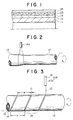
- Figs. 1 to 6 are drawings of an embodiment of the present invention in which:
- Fig. 1 is a sectional view of the embodiment at the end of processing of an antisticking layer,
- Fig. 2 is a front view of the embodiment during the formation of a resistor layer by spray coating,
- Fig. 3 is a front view of the embodiment during the formation of a groove by laser processing,
- Fig. 4 is a partially sectional front view of the embodiment when the electrical resistance of a resistor layer is measured;
- Fig. 5 is a sectional view of the embodiment at the end of processing of power supplying parts and the antisticking layer; and
- Fig. 6 is a sectional view of the embodiment when no reinforcing insulating layer is provided; and
- Figs. 7 to 9 are drawings of a conventional roll in which:
- Fig. 7 is a sectional view of the same after the formation of a heating resistor layer by thermal spray coating;
- Fig. 8 is a sectional view of the same after the removal of a metal wire; and
- Fig. 9 is a sectional view of the same at the end of processing of an antisticking layer.
- Although the present invention is described below with reference to the attached drawings, the same reference numeral denotes the same member having the same function.
- An
insulating layer 12 is formed in a thin layer having a thickness of, for example, about 200 µm, on the surface of ahollow metal tube 11 by plasma thermal spray coating alumina, magnesia alumina spinel or the like using a thermalspray coating torch 14a while rotating thehollow tube 11, as shown in Fig. 2. Aresistor layer 13 is then formed in a thin layer having a thickness of, for example, about 30 to 100 µm, on the surface of the insulatinglayer 12 by plasma thermal spray coating nichrome, stainless, aluminum, aluminum alloy brazing filler metals, a titania-chromia mixture, a titania-nichrome mixture, a silica-alumina-nickel mixture or the like using thespray coating torch 14a. Nichrome aluminum containing 6% of aluminum relative to the total of nichrome consisting of 80% of nickel and 20% of chromium is excellent as a resistor material. - (1) When a power source is connected to both ends of the heating resistor layer so as to cause electric current to flow through the heating resistor layer and increase the temperature thereof by heating, if nichrome aluminum (NiCr.Al) is used as a material for the heating resistor, only a slight difference occurs between the electric resistance values at the starting time of electrical charge of the resistor and the time the temperature reaches a predetermined value, for example, 200°C, because the temperature coefficient of the resistor is as low as 100 to 300 PPM. There is thus no problem in that a fuse is blown owing to a large current flowing at the start of electrical charge, or in that the temperature rising time of the heating element is long owing to a low current flowing at the start of electrical charge.
- (2) Fluorine resin is frequently used in the antisticking layer, and the baking temperature thereof is about 360 to 400°C. The electric resistance value of NiCr.Al is not changed by baking at such a relatively high temperature.
- In addition, although a heat fixing roll is on-off controlled so as to be kept at a temperature of about 200°C, the electric resistance value of NiCr.Al is stable even if a heat fixing roll is operated for a long time at the above high temperature.
- Aluminum can be appropriately mixed within the range of 0.5 to 4% relative to nichrome. The components of nichrome are also not limited to the above-described mixing ratio.
- As shown in Fig. 3, the
hollow tube 11 is rotated while alaser irradiation head 16 being moved in the direction shown by the arrow A16 in the drawing. When alaser beam 10 converged to a narrow beam, for example, a YAG laser beam, is applied to the surface of theresistor layer 13, which is made of a metal or mainly made of a metal, is heated by thelaser beam 10 so that a portion of theresistor layer 13 to which thelaser beam 10 is applied is evaporated. - Since the insulating
layer 12 is made of ceramics such as alumina, magnesia-alumina spinel or the like, as described above, it has a melting point and a boiling point which are higher than those of metals. The output of thelaser beam 10 and the irradiation time can thus be regulated so that theinsulating layer 12 is hardly worn out, while the irradiated portion of the resistor layer is evaporated, whereby the surface of theinsulating layer 12 can be exposed at the bottom of agroove 19. - The
helical groove 19 can be formed with parallel portions at predetermined distances H by controlling the speed of movement of thelaser irradiation head 16 and the rotational speed of thehollow tube 11. - The distance H between the adjacent parallel portions of the
groove 19 is determined by the resistivity value, the thickness, the required heating value and so on of theresistor layer 13 and is about 2 to 10 mm. - The width D of the
groove 19 is about 100 to 200 µm. - When many heat fixing rolls are produced, if the electric resistance value between both ends of each of the
heating resistors 14 is out of a predetermined range, i.e., if the values vary, the rate of nondefective products is decreased. - The electric resistance value is affected by the thickness of the
resistor layer 13, the width W of the screw-like heating resistor 14 and the conditions of thermal spray coating. - Although the width W of the
heating resistor 14 can be precisely controlled by a method using the above-described laser beam, it is very difficult to maintain a constant thickness of theresistor layer 13 and constant conditions of spray coating during the operation of a production apparatus over a long time and thus difficult to increase the rate of nondefective products. However, this problem can be resolved by the following method: - The
resistor layer 13 is first formed in such a manner that the thickness of theresistor layer 13 is as constant as possible, and the conditions of thermal spray coating are also constant.Power supplying parts 21 are then formed at both ends of theresistor layer 13, and the measuring terminals of resistance measuring instrument of an electric resistance compensator are brought into contact with thepower supplying parts 21, as shown in Fig. 4. - In this way, the electric resistance value between both ends of the
heating resistor layer 13 can be precisely measured by measuring the resistance using thepower supplying parts 21. - If the result of measurement deviates from a standard value, the width W of the
heating resistor 14 can be determined by calculation so that the electric resistance value between both ends of theheating resistor layer 13 is a predetermined value in correspondence with the value obtained measurement. - Although the calculating method is not described below, the electric resistance value decreases with an increase in width W of the
heating resistor 14 and conversely increases with a reduction in width W. - The rotational speed of the
hollow tube 11 and the moving speed of thelaser irradiation head 16 are thus programmed so that the width W of theheating resistor 14 determined by calculation can be obtained Thegroove 19 with a depth reaching the surface of theinsulating layer 12 is formed by helically cutting theresistor layer 13 by using the laser beam in accordance with the program formed. As a result of laser trimming, the dispersion of the electric resistance values of theheating resistors 14 can be restricted to a value within the range of +5%. - As a matter of course, a series of processes (laser trimming) such as the measurement of the electric resistance value of the
resistor layer 13, the calculation of the width of theheating resistor 14, the calculation of the rotational speed of the hollow tube, the moving speed of thelaser irradiation head 16, the programming and other executions are automatically carried out After thegroove 19 has been formed, the reinforcinginsulating layer 23 is formed on the surface of theheating resistor 14 and on the internal surface of thegroove 19, as shown in Fig. 5. In this case, the reinforcing insulatinglayer 23 is formed by a method of plasma spray coating a ceramics material such as alumina, magnesia-alumina spinel or the like so that the thickness thereof is 100 to 250 µm. - When no power supplying part is disposed on the
resistor layer 13, thepower supplying parts 21 are formed at both ends of theheating resistor 14, as shown in Fig. 5. Theheating parts 21 are formed by a method of spray coating or plasma thermal spray coating a conductive material such as copper, a copper alloy or the like. - The
antisticking layer 25 is then formed on the reinforcing insulatinglayer 23 by a method of powder coating fluorine resin such as PFA or the like. - The material for the
antisticking layer 25 is not limited to the fluorine resin such as PFA or the like, and silicone and other resins having excellent antisticking properties can be used as materials for theantisticking layer 25. The method of forming theantisticking layer 25 is not limited to the power coating method, and other known liquid coating methods can be employed. - When the
antisticking layer 25 has a high level of electrical insulating properties, theantisticking layer 25 is sometimes formed directly on the surface of theheating resistor 14 without the reinforcing insulatinglayer 23 disposed thereon, as shown in Fig. 6. - In this way, the direct heating-type heat fixing roll can be manufactured at a low cost with a high rate of nondefective products.
- When the
groove 19 is formed by using thelaser beam 10, the width D of thegroove 19 can be reduced to 100 to 200 µm, as described above. Even if theantisticking layer 25 or the reinforcing insulatinglayer 23 and theantisticking layer 25 are formed, therefore, there is no problem of occurring a depressed line because thegroove 19 is filled with small amounts of the antisticking material and the reinforcing insulating material. - The
antisticking layer 25 thus has a smooth surface and need not be ground. - As described above, since the present invention employs the laser beam for forming the
helical groove 19 in the heating resistor layer so that the insulating layer is exposed to air, it is possible to reduce the width of the groove and completely separate the adjacent portions of the heating resistor from each other. - It is therefore unnecessary to wind and remove the metal wire, and no depressed stripe occurs in the antisticking layer, apart from conventional fixing rolls. Since the surface of the
antisticking layer 25 need not be ground, the production cost can be reduced. In addition, the positioning of thehelical groove 19 using the electric resistance compensator enables a reduction in dispersion of the electric resistance value of the heat fixing roll produced and an increase in the rate of nondefective products. - Further, an electronic copying machine provided with a heat fixing roll for copying machines, which has the helical heating resistor layer formed by laser cutting, is capable of uniformly controlling the temperature distribution on the roll. Uniformity therefor occurs between the central portion and both ends of the image copied, and a uniform and clear image can be copied.
- An electronic copying machine provided with a heating fixing roll for a copying machine which has the helical nichrome-aluminum heating resistor layer formed by laser cutting has the aforementioned effect and comprises the heating resistor which has a low temperature coefficient and uniformly generates heat at the start of electrical charge and during stationary use. It is therefore possible to ensure that the allowable power consumed (heating value) by the heat fixing roll for a copying machine is always kept at the maximum and to obtain the following effects:
- (1) Since the rising time of a copying machine is short, a waiting time from the time a switch is turned on can be reduced.
- (2) The heating value is not reduced during stationary use, as described above, and heat is easily supplied to the heating resistor in correspondence with the heat required for fixing. It is therefore possible to significantly increase the amount of copying paper (the number of sheets of copying paper per unit time). Namely, it is possible to improve the copying ability of the copying machine.
Claims (10)
Applications Claiming Priority (2)
| Application Number | Priority Date | Filing Date | Title |
|---|---|---|---|
| JP131139/89 | 1989-05-24 | ||
| JP1131139A JPH02308291A (en) | 1989-05-24 | 1989-05-24 | Heat fixing roll for copying machine and its manufacture |
Publications (2)
| Publication Number | Publication Date |
|---|---|
| EP0399376A2 true EP0399376A2 (en) | 1990-11-28 |
| EP0399376A3 EP0399376A3 (en) | 1992-06-10 |
Family
ID=15050908
Family Applications (1)
| Application Number | Title | Priority Date | Filing Date |
|---|---|---|---|
| EP19900109374 Withdrawn EP0399376A3 (en) | 1989-05-24 | 1990-05-17 | Heat fixing roll for copying machine, method of producing the same and electronic copying machine provided with the same |
Country Status (4)
| Country | Link |
|---|---|
| US (1) | US5065193A (en) |
| EP (1) | EP0399376A3 (en) |
| JP (1) | JPH02308291A (en) |
| CA (1) | CA2017365A1 (en) |
Cited By (4)
| Publication number | Priority date | Publication date | Assignee | Title |
|---|---|---|---|---|
| EP1217466A1 (en) * | 2000-12-22 | 2002-06-26 | Samsung Electronics Co., Ltd. | Fusing roller assembly including a resistance coil for heating wound around a heat pipe roller for electrophotographic image forming apparatus |
| US6571080B2 (en) | 2000-12-22 | 2003-05-27 | Samsung Electronics Co., Ltd. | Fusing roller assembly having working fluid and heater coil for quick heating and low power consumption for an electrophotographic image forming apparatus and method of making the same |
| US6580896B2 (en) | 2000-12-22 | 2003-06-17 | Samsung Electronics Co., Ltd. | Fusing roller assembly for electrophotographic image forming apparatus |
| EP2009648A1 (en) | 2001-12-19 | 2008-12-31 | Watlow Electric Manufacturing Company | Heating and/or cooling device with multiple layers |
Families Citing this family (20)
| Publication number | Priority date | Publication date | Assignee | Title |
|---|---|---|---|---|
| FI90098C (en) * | 1992-04-14 | 1993-12-27 | Valmet Paper Machinery Inc | FOERFARANDE VID BELAEGGNINGEN AV EN MITTVALS I PRESSEN AV EN PAPPERSMASKIN OCH MITTVALS FOER EN PRESS I EN PAPPERSMASKIN |
| JPH06118829A (en) * | 1992-10-02 | 1994-04-28 | Fuji Xerox Co Ltd | Local heating device and device equipped with the same |
| US5408070A (en) * | 1992-11-09 | 1995-04-18 | American Roller Company | Ceramic heater roller with thermal regulating layer |
| US5722025A (en) * | 1995-10-24 | 1998-02-24 | Minolta Co., Ltd. | Fixing device |
| JPH09250539A (en) * | 1996-03-19 | 1997-09-22 | Shin Etsu Polymer Co Ltd | Semi-conductive roll and manufacturing method thereof |
| EP0881550B1 (en) * | 1997-05-30 | 2004-01-02 | Kyocera Corporation | Heating roller for fixing toner |
| CZ301527B6 (en) * | 2000-02-28 | 2010-04-07 | Vaw Aluminium Ag | Process for producing surface-alloyed cylindrical, partially cylindrical or hollow cylindrical component and device for making the same |
| ATE515990T1 (en) * | 2000-05-19 | 2011-07-15 | Advanced Bio Prosthetic Surfac | METHOD AND DEVICE FOR PRODUCING AN INTRAVASCULAR STENT |
| KR100388997B1 (en) * | 2001-02-22 | 2003-06-25 | 삼성전자주식회사 | Heating roller assembly for electrophotographic printer |
| WO2004013900A2 (en) * | 2002-08-05 | 2004-02-12 | Research Foundation Of The State University Of New York | System and method for manufacturing embedded conformal electronics |
| JP5017522B2 (en) * | 2005-09-13 | 2012-09-05 | 株式会社アイ.エス.テイ | Planar heating element and manufacturing method thereof |
| KR101474566B1 (en) * | 2005-10-26 | 2014-12-18 | 마이크로닉 마이데이터 아베 | Lighting apparatus and method |
| US8122846B2 (en) | 2005-10-26 | 2012-02-28 | Micronic Mydata AB | Platforms, apparatuses, systems and methods for processing and analyzing substrates |
| KR100654360B1 (en) * | 2005-10-27 | 2006-12-08 | 삼성전자주식회사 | Semiconductor integrated circuit device and its manufacturing method |
| US20100077602A1 (en) * | 2008-09-27 | 2010-04-01 | Wolfgang Kollenberg | Method of making an electrical heater |
| US20130215202A1 (en) * | 2012-02-22 | 2013-08-22 | Kevin David Koller | Helical dryer path for a print substrate web |
| WO2014140047A2 (en) | 2013-03-12 | 2014-09-18 | Micronic Mydata AB | Method and device for writing photomasks with reduced mura errors |
| WO2014140046A2 (en) | 2013-03-12 | 2014-09-18 | Micronic Mydata AB | Mechanically produced alignment fiducial method and device |
| CN104625426B (en) * | 2013-11-11 | 2017-11-07 | 昆山思拓机器有限公司 | One kind is used for medical long solenoid laser cutting method |
| JP6652346B2 (en) * | 2015-08-07 | 2020-02-19 | 住友電気工業株式会社 | Self-heating type fixing roller |
Family Cites Families (9)
| Publication number | Priority date | Publication date | Assignee | Title |
|---|---|---|---|---|
| US958144A (en) * | 1909-08-21 | 1910-05-17 | Hyatt Roller Bearing Co | Process of making helical rolls. |
| NL6707448A (en) * | 1967-05-30 | 1968-12-02 | ||
| GB1549218A (en) * | 1976-06-18 | 1979-08-01 | Xerox Corp | Method and appratus for forming a desired surface cinfiguration on a resilient roller |
| JPS5469896A (en) * | 1977-11-15 | 1979-06-05 | Koyo Seiko Co Ltd | Method of machining work outer surface with laser beam |
| EP0262833B1 (en) * | 1986-09-22 | 1992-10-14 | Onoda Cement Company, Ltd. | Thermal fixing roller for use in a copying machine and method for manufacturing the same |
| DE3881906T2 (en) * | 1987-02-23 | 1994-01-20 | Centre Rech Metallurgique | Process for surface marking of rolling mill rolls. |
| JPS6416584A (en) * | 1987-07-13 | 1989-01-20 | Mitsui Toatsu Chemicals | Preparation of aqueous solution of tryptophan synthase |
| US4866826A (en) * | 1987-12-22 | 1989-09-19 | Makoto Koide | Method of making squeezing roll and squeezing equipment |
| DE3809821A1 (en) * | 1988-03-23 | 1989-10-05 | Georg Sillner | Device for producing film resistors, and a method for controlling this device |
-
1989
- 1989-05-24 JP JP1131139A patent/JPH02308291A/en active Pending
-
1990
- 1990-05-17 EP EP19900109374 patent/EP0399376A3/en not_active Withdrawn
- 1990-05-18 US US07/525,903 patent/US5065193A/en not_active Expired - Fee Related
- 1990-05-23 CA CA002017365A patent/CA2017365A1/en not_active Abandoned
Cited By (5)
| Publication number | Priority date | Publication date | Assignee | Title |
|---|---|---|---|---|
| EP1217466A1 (en) * | 2000-12-22 | 2002-06-26 | Samsung Electronics Co., Ltd. | Fusing roller assembly including a resistance coil for heating wound around a heat pipe roller for electrophotographic image forming apparatus |
| US6571080B2 (en) | 2000-12-22 | 2003-05-27 | Samsung Electronics Co., Ltd. | Fusing roller assembly having working fluid and heater coil for quick heating and low power consumption for an electrophotographic image forming apparatus and method of making the same |
| US6580896B2 (en) | 2000-12-22 | 2003-06-17 | Samsung Electronics Co., Ltd. | Fusing roller assembly for electrophotographic image forming apparatus |
| EP2009648A1 (en) | 2001-12-19 | 2008-12-31 | Watlow Electric Manufacturing Company | Heating and/or cooling device with multiple layers |
| US9029742B2 (en) | 2001-12-19 | 2015-05-12 | Watlow Electric Manufacturing Company | Method for the production of an electrically conductive resistive layer and heating and/or cooling device |
Also Published As
| Publication number | Publication date |
|---|---|
| JPH02308291A (en) | 1990-12-21 |
| CA2017365A1 (en) | 1990-11-24 |
| EP0399376A3 (en) | 1992-06-10 |
| US5065193A (en) | 1991-11-12 |
Similar Documents
| Publication | Publication Date | Title |
|---|---|---|
| US5065193A (en) | Heat fixing roll for copying machine, method of producing the same and electronic copying machine provided with the same | |
| EP0262833B1 (en) | Thermal fixing roller for use in a copying machine and method for manufacturing the same | |
| US11845223B2 (en) | Apparatus, system and method of operating an additive manufacturing nozzle | |
| EP3954177B1 (en) | Method to compensate for irregularities in a thermal system | |
| JP2015197971A (en) | Heater, fixation device with the same, image forming apparatus, heating device, and manufacturing method of heater | |
| SE438057B (en) | SET TO REGULATE THE RESISTANCE OF A TERMISTOR | |
| US20250375938A1 (en) | Apparatus, system and method of operating an additive manufacturing nozzle | |
| US6323460B1 (en) | Image heating apparatus in which first and second heating resistors are within a width of a nip through which a recording material passes | |
| US6071347A (en) | Apparatus for manufacturing heater roller | |
| RU2052352C1 (en) | Method of melting-down of organic product with the aid of microwaves and device for its accomplishment | |
| JPH0636121B2 (en) | Heat fixing roll for copier | |
| JPH05258843A (en) | Fixing heater and its manufacture | |
| JP3441325B2 (en) | Heat roller for fixing and method of manufacturing the same | |
| JPH11282297A (en) | Heat fixing roller | |
| JPH06275368A (en) | Ceramic heater | |
| EP4559288A1 (en) | Electric heating element production method | |
| JPH05181376A (en) | Heater and method for adjusting resistance value of heater | |
| JPH0433288A (en) | Heating resistor pattern forming method on fixing roller | |
| JPH05216360A (en) | Fixing heater and manufacturing method thereof | |
| JP3090395B2 (en) | Electric soldering iron device | |
| JPH06267864A (en) | Vapor growth device | |
| JPH1074579A (en) | Cylindrical heater | |
| JPH0340390A (en) | Manufacture of heater | |
| JPH03114755A (en) | Heating element | |
| JPH01106408A (en) | Manufacture of resistance thin-film |
Legal Events
| Date | Code | Title | Description |
|---|---|---|---|
| PUAI | Public reference made under article 153(3) epc to a published international application that has entered the european phase |
Free format text: ORIGINAL CODE: 0009012 |
|
| AK | Designated contracting states |
Kind code of ref document: A2 Designated state(s): CH DE FR GB LI |
|
| PUAL | Search report despatched |
Free format text: ORIGINAL CODE: 0009013 |
|
| AK | Designated contracting states |
Kind code of ref document: A3 Designated state(s): CH DE FR GB LI |
|
| 17P | Request for examination filed |
Effective date: 19920723 |
|
| 17Q | First examination report despatched |
Effective date: 19931203 |
|
| STAA | Information on the status of an ep patent application or granted ep patent |
Free format text: STATUS: THE APPLICATION IS DEEMED TO BE WITHDRAWN |
|
| 18D | Application deemed to be withdrawn |
Effective date: 19941201 |