EP0399590A2 - Frame - Google Patents
Frame Download PDFInfo
- Publication number
- EP0399590A2 EP0399590A2 EP90201210A EP90201210A EP0399590A2 EP 0399590 A2 EP0399590 A2 EP 0399590A2 EP 90201210 A EP90201210 A EP 90201210A EP 90201210 A EP90201210 A EP 90201210A EP 0399590 A2 EP0399590 A2 EP 0399590A2
- Authority
- EP
- European Patent Office
- Prior art keywords
- frame
- piece
- frame profile
- clamping device
- clamping
- Prior art date
- Legal status (The legal status is an assumption and is not a legal conclusion. Google has not performed a legal analysis and makes no representation as to the accuracy of the status listed.)
- Granted
Links
Images


Classifications
-
- E—FIXED CONSTRUCTIONS
- E06—DOORS, WINDOWS, SHUTTERS, OR ROLLER BLINDS IN GENERAL; LADDERS
- E06B—FIXED OR MOVABLE CLOSURES FOR OPENINGS IN BUILDINGS, VEHICLES, FENCES OR LIKE ENCLOSURES IN GENERAL, e.g. DOORS, WINDOWS, BLINDS, GATES
- E06B1/00—Border constructions of openings in walls, floors, or ceilings; Frames to be rigidly mounted in such openings
- E06B1/56—Fastening frames to the border of openings or to similar contiguous frames
- E06B1/60—Fastening frames to the border of openings or to similar contiguous frames by mechanical means, e.g. anchoring means
- E06B1/6046—Clamping means acting perpendicular to the wall opening; Fastening frames by tightening or drawing them against a surface parallel to the opening
- E06B1/6061—Clamping means acting perpendicular to the wall opening; Fastening frames by tightening or drawing them against a surface parallel to the opening with separate clamping means acting on opposite wall or associated surfaces
Definitions
- the invention relates to a frame, comprising at least one substantially U-shaped frame profile gripping around a wall edge and at least one clamping device, which clamping device comprises: - a substantially U-shaped gripping bracket whereof in each case one of two legs clamps on one of the two flanges of the frame profile; - a bridging piece supporting with two outer ends relative to the gripping bracket; and - a screw connection acting between bridging piece and gripping bracket.
- Such a frame is known from the Italian patent specification 1127936.
- a deformable gripping bracket is therein welded to a deformable bridging piece.
- Much force is required to deform the assembly of gripping bracket and bridging piece in principle welded together as a closed tube.
- Much manual force is therefore needed to effect the required clamping of the frame profile onto the wall edge.
- the gripping bracket and the bridging piece both have a breadth which is slightly greater than the breadth of the wall edge. They occupy a lot of space within the frame profile so that the frame profile must have broad flanges.
- the invention has for its object to provide a frame of the type referred to in the preamble wherein a better fixed clamping of the frame profile on the wall edge can be effected with similar or even less manual force.
- the frame according to the invention has the feature that the gripping bracket has a screwed piece which is connected to two clamping pieces; that the bridging piece is arranged between the frame profile and the gripping bracket; and that the bridging piece grips at an interval from the screwed piece onto the clamping pieces between the screwed piece and the free ends of the clamping pieces.
- the invention further provides a frame whereof the frame profile can have narrower flanges because the bridging piece extends only over a length which is situated within the space of a recess of the frame present next to a groove.
- the present invention provides a frame wherein additional deformations of the frame profiles for the positioning of the clamping devices are not necessary.
- a frame comprising at least one substantially U-shaped frame profile gripping around the wall edge wherein at least one clamping device is present to clamp the frame profile fixedly onto a wall edge has the feature that the clamping device is provided with a fixing sleeve which fixes the clamping device relative to an operating opening arranged in the frame profile.
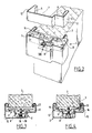
- Fig. 1 shows a frame 1 whereof frame profiles 2 are clamped fixedly to wall edges 3 by means of clamping devices 4.
- the frame profile 2 is substantially U-shaped, has two flanges 12 with edges 5 bent over gutter-like and has a groove 6 for receiving a door edge. Adjoining this groove 6 the frame profile 2 has a recess 7 wherein is arranged a bridging piece 8 of a clamping device 4 which also further comprises U-shaped gripping bracket 9 two legs 10 of which grip in the gutter-like edges 5. As shown particularly in fig. 5-7, the bracket 9 has a U-shaped section practically along its entire length and has therefore a considerable bending strength. The bracket 9 is provided with indentations 12 at the corners.
- the bracket 9 has three elements, namely a screwed piece 13 and two clamping pieces 14 bent over in an L-shape and mutually connected via two deformable bracket pieces 15 arranged on either side of the screwed piece 13. At the location of these deformable bracket pieces 15 the flanges 17 of the U-shaped bracket profile are cut away while the body 18 has also been subjected to local stamping out 19 at that position.
- the body 18 further has two protuberances 20 which serve as stop.
- the screwed piece 13 has a threaded hole 21.
- the bridging piece 8 has a middle piece 22 with U-shaped profile and two support pieces 24 which are connected to the middle piece 22 via corners 26 reinforced by hollowed portions 25.
- the support pieces 24 each have a cut-away portion 27 wherewith they grip freely pivoting around the U profile-shaped clamping pieces 14 and therein stop against the protuberances 20.
- a socket head screw 30 is inserted through a central hole 31 of the middle piece 22 and screwed into the threaded hole 21.
- the gripping bracket 9 is deformed by tightening the socket head screw 30 and by deformation of the deforming pieces 15 so that clamping pieces 14 optionally provided with teeth 33 clamp the edges 5 fixedly against the wall edge 3 with considerable force.
- the portions of the clamping pieces 9 adjoining the deforming pieces 15 further have extra reinforcing edges 34.
- the socket head screw 30 can be accessed with a hexagonal spanner via an operating opening 36 of the frame profile 2 wherein is arranged a fixing sleeve 37 of elastic plastic.
- the fixing sleeve 37 has a groove 38 for receiving the edge 39 of the operating opening 36 and further axial slits 40 for deformation during assembly.
- the fixing sleeve 37 When the clamping device 4 is pushed with the socket head screw 30 onto its position opposite the operating opening 36 the fixing sleeve 37 is pushed into the operating opening 36 by deforming this radially, making use therein of the conical outer surface 43, while the head 44 of the socket head screw 30 falls into the internal conical bore 45.
- the frame profile 2 is transported to the building site with the thus positioned clamping device 4. After clamping the frame profile 2 in place on a wall edge 3 the fixing sleeve 37 is closed off by means of a cover 47 of elastic material, the edge 48 whereof clamps behind an inner edge 49 of the fixing sleeve 37.
- the embodiment of the clamping device 54 in fig. 10-12 is identical to the clamping device 4, with the understanding that with the clamping device 54 practically the entire space of the recess 7 adjoining the groove 6 is used for accommodating the bridging piece 58, which has a greater length.
- the screwed piece 13 has a rolled screw thread and is deformable around the screw 30.
- the clamping pieces 14 of the gripping bracket 59 are reinforced with a pressed recess 61 running over the bend 60.
- the frame profile 2 in fig. 10 and 11 has an S-shaped edge 63 with an anchoring edge 64 penetrating into the surface of the wall edge 3.
- the fixing sleeve 66 has elastic, outward protruding clip hooks 67 which grip behind a hole edge 68.
- the flanges 12 of the frame profile 2 do not have to be broad because the inner space of the frame profile 2 is well utilized so that considerable variations of the size of the door opening of the wall can be accommodated in the window profile 2 as a wall edge 3 penetrating to a greater or lesser extent into the clamping device 4.
- the clamping device 74 in fig. 13 has two separate clamping pieces 75 and 76 which hook into one another by means of a hinge 77 and are swivelled toward one another by means of a socket head screw 30 for clamping a frame profile 2 to a wall edge.
- the socket screw head 30 is again enclosed in a conical bore 45 of a fixing sleeve 37.
Landscapes
- Engineering & Computer Science (AREA)
- Mechanical Engineering (AREA)
- Civil Engineering (AREA)
- Structural Engineering (AREA)
- Clamps And Clips (AREA)
- Mirrors, Picture Frames, Photograph Stands, And Related Fastening Devices (AREA)
- Connection Of Plates (AREA)
- Forms Removed On Construction Sites Or Auxiliary Members Thereof (AREA)
- Sheet Holders (AREA)
- Mutual Connection Of Rods And Tubes (AREA)
Abstract
Description
- The invention relates to a frame, comprising at least one substantially U-shaped frame profile gripping around a wall edge and at least one clamping device, which clamping device comprises:
- a substantially U-shaped gripping bracket whereof in each case one of two legs clamps on one of the two flanges of the frame profile;
- a bridging piece supporting with two outer ends relative to the gripping bracket; and
- a screw connection acting between bridging piece and gripping bracket. - Such a frame is known from the Italian patent specification 1127936. A deformable gripping bracket is therein welded to a deformable bridging piece. Much force is required to deform the assembly of gripping bracket and bridging piece in principle welded together as a closed tube. Much manual force is therefore needed to effect the required clamping of the frame profile onto the wall edge.
- With the stated known frame the gripping bracket and the bridging piece both have a breadth which is slightly greater than the breadth of the wall edge. They occupy a lot of space within the frame profile so that the frame profile must have broad flanges.
- The invention has for its object to provide a frame of the type referred to in the preamble wherein a better fixed clamping of the frame profile on the wall edge can be effected with similar or even less manual force. To this end the frame according to the invention has the feature that the gripping bracket has a screwed piece which is connected to two clamping pieces;
that the bridging piece is arranged between the frame profile and the gripping bracket; and
that the bridging piece grips at an interval from the screwed piece onto the clamping pieces between the screwed piece and the free ends of the clamping pieces. - The invention further provides a frame whereof the frame profile can have narrower flanges because the bridging piece extends only over a length which is situated within the space of a recess of the frame present next to a groove.
- With frames it is usual to attach the clamping devices positioned on the frame profiles before they are transported to a building site. To this end the frame profiles are for example deformed close to the clamping devices so that each clamping device is for instance enclosed between two deformations of the frame profile.
- The present invention provides a frame wherein additional deformations of the frame profiles for the positioning of the clamping devices are not necessary. For this purpose according to the invention a frame comprising at least one substantially U-shaped frame profile gripping around the wall edge wherein at least one clamping device is present to clamp the frame profile fixedly onto a wall edge has the feature that the clamping device is provided with a fixing sleeve which fixes the clamping device relative to an operating opening arranged in the frame profile.
- Mentioned and other features of the invention will become apparent from the description following hereinafter of embodiments of frames according to the invention.
- In the drawings in schematic form:
- fig. 1 shows a broken away perspective view of a frame according to the invention;
- fig. 2 shows on a larger scale a broken away perspective view of detail II from fig. 1;
- fig. 3 and 4 show on a larger scale a section along line III-III from fig. 1 respectively before and after fixed clamping of a frame profile;
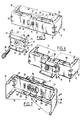
- fig. 5 shows on a larger scale a perspective view of the disassembled clamping device of the frame of fig. 1;
- fig. 6 and 7 show perspective views of the fitted clamping device of fig. 5 viewed in opposing directions;
- fig. 8 shows on a larger scale a perspective broken away view of detail VIII from fig. 2 in disassembled state;
- fig. 9 shows a section along line IX-IX from fig. 8 in mounted position;
- fig. 10 and 11 show sections corresponding with fig. 3 and 4 respectively and relating to another frame according to the invention;
- fig. 12 shows a perspective view of the clamping device of fig. 10 and 11;
- fig. 13 shows a broken away perspective view of yet another frame according to the invention; and
- fig. 14 shows on a larger scale a section along line XIV-XIV in fig. 13.
- Fig. 1 shows a frame 1 whereof frame profiles 2 are clamped fixedly to
wall edges 3 by means of clamping devices 4. - The
frame profile 2 is substantially U-shaped, has twoflanges 12 withedges 5 bent over gutter-like and has a groove 6 for receiving a door edge. Adjoining this groove 6 theframe profile 2 has a recess 7 wherein is arranged abridging piece 8 of a clamping device 4 which also further comprises U-shaped gripping bracket 9 twolegs 10 of which grip in the gutter-like edges 5. As shown particularly in fig. 5-7, the bracket 9 has a U-shaped section practically along its entire length and has therefore a considerable bending strength. The bracket 9 is provided withindentations 12 at the corners. The bracket 9 has three elements, namely a screwedpiece 13 and two clampingpieces 14 bent over in an L-shape and mutually connected via twodeformable bracket pieces 15 arranged on either side of the screwedpiece 13. At the location of thesedeformable bracket pieces 15 theflanges 17 of the U-shaped bracket profile are cut away while thebody 18 has also been subjected to local stamping out 19 at that position. - The
body 18 further has twoprotuberances 20 which serve as stop. The screwedpiece 13 has a threadedhole 21. Thebridging piece 8 has amiddle piece 22 with U-shaped profile and twosupport pieces 24 which are connected to themiddle piece 22 viacorners 26 reinforced by hollowedportions 25. Thesupport pieces 24 each have a cut-awayportion 27 wherewith they grip freely pivoting around the U profile-shapedclamping pieces 14 and therein stop against theprotuberances 20. - From the outside a
socket head screw 30 is inserted through acentral hole 31 of themiddle piece 22 and screwed into the threadedhole 21. As fig. 3 and 4 show, the gripping bracket 9 is deformed by tightening thesocket head screw 30 and by deformation of the deformingpieces 15 so that clampingpieces 14 optionally provided withteeth 33 clamp theedges 5 fixedly against thewall edge 3 with considerable force. The portions of the clamping pieces 9 adjoining the deformingpieces 15 further have extra reinforcing edges 34. - As is to be seen in fig. 3, 4, 8 and 9 the
socket head screw 30 can be accessed with a hexagonal spanner via anoperating opening 36 of theframe profile 2 wherein is arranged a fixingsleeve 37 of elastic plastic. The fixingsleeve 37 has agroove 38 for receiving theedge 39 of theoperating opening 36 and furtheraxial slits 40 for deformation during assembly. - When the clamping device 4 is pushed with the
socket head screw 30 onto its position opposite theoperating opening 36 the fixingsleeve 37 is pushed into theoperating opening 36 by deforming this radially, making use therein of the conicalouter surface 43, while thehead 44 of thesocket head screw 30 falls into the internal conical bore 45. Theframe profile 2 is transported to the building site with the thus positioned clamping device 4. After clamping theframe profile 2 in place on awall edge 3 the fixingsleeve 37 is closed off by means of acover 47 of elastic material, theedge 48 whereof clamps behind aninner edge 49 of the fixingsleeve 37. - The embodiment of the
clamping device 54 in fig. 10-12 is identical to the clamping device 4, with the understanding that with the clampingdevice 54 practically the entire space of the recess 7 adjoining the groove 6 is used for accommodating thebridging piece 58, which has a greater length. In the clamping position thelong bridging piece 58 can support over a considerable length against the inner side of theframe profile 2. The screwedpiece 13 has a rolled screw thread and is deformable around thescrew 30. The clampingpieces 14 of the grippingbracket 59 are reinforced with a pressedrecess 61 running over thebend 60. - The
frame profile 2 in fig. 10 and 11 has an S-shapededge 63 with an anchoringedge 64 penetrating into the surface of thewall edge 3. The fixingsleeve 66 has elastic, outward protruding clip hooks 67 which grip behind ahole edge 68. - In the use of the clamping device 4 the
flanges 12 of theframe profile 2 do not have to be broad because the inner space of theframe profile 2 is well utilized so that considerable variations of the size of the door opening of the wall can be accommodated in thewindow profile 2 as awall edge 3 penetrating to a greater or lesser extent into the clamping device 4. - The clamping
device 74 in fig. 13 has twoseparate clamping pieces hinge 77 and are swivelled toward one another by means of asocket head screw 30 for clamping aframe profile 2 to a wall edge. Thesocket screw head 30 is again enclosed in aconical bore 45 of a fixingsleeve 37.
Claims (5)
- a substantially U-shaped gripping bracket (9) whereof one of two legs (10) grips in each case onto one of the two flanges (80) of the frame profile (2);
- a bridging piece (8) which supports with two ends (24) relative to the gripping bracket (9); and
- a screw connection (30) acting between bridging piece (8) and gripping bracket (9),
characterized in that the gripping bracket (9) has a screwed piece (13) which is connected to two clamping pieces (14);
that the bridging piece (8) is arranged between the frame profile (2) and the gripping bracket (9); and
that the bridging piece (8) grips at an interval from the screwed piece (13) onto the clamping pieces (14) between the screwed piece (13) and the free ends of the clamping pieces (14).
Applications Claiming Priority (2)
| Application Number | Priority Date | Filing Date | Title |
|---|---|---|---|
| NL8901264A NL8901264A (en) | 1989-05-19 | 1989-05-19 | FRAME. |
| NL8901264 | 1989-05-19 |
Publications (3)
| Publication Number | Publication Date |
|---|---|
| EP0399590A2 true EP0399590A2 (en) | 1990-11-28 |
| EP0399590A3 EP0399590A3 (en) | 1991-03-27 |
| EP0399590B1 EP0399590B1 (en) | 1993-07-21 |
Family
ID=19854682
Family Applications (1)
| Application Number | Title | Priority Date | Filing Date |
|---|---|---|---|
| EP19900201210 Expired - Lifetime EP0399590B1 (en) | 1989-05-19 | 1990-05-14 | Frame |
Country Status (4)
| Country | Link |
|---|---|
| EP (1) | EP0399590B1 (en) |
| DE (1) | DE69002279T2 (en) |
| ES (1) | ES2042198T3 (en) |
| NL (1) | NL8901264A (en) |
Cited By (1)
| Publication number | Priority date | Publication date | Assignee | Title |
|---|---|---|---|---|
| EP3712367A1 (en) * | 2019-03-18 | 2020-09-23 | SFS Intec Holding AG | Embrasure clamp |
Family Cites Families (6)
| Publication number | Priority date | Publication date | Assignee | Title |
|---|---|---|---|---|
| US3250049A (en) * | 1963-12-20 | 1966-05-10 | Sklar Samuel | Adjustable wall clamping means for door bucks |
| GB1305196A (en) * | 1969-10-14 | 1973-01-31 | ||
| FR2355152A1 (en) * | 1976-06-18 | 1978-01-13 | Rauc Ctre Rech Architect Urba | Partition gap compensation device - comprises profiled section with open groove accommodating partition and adjustable stops |
| US4126975A (en) * | 1977-01-21 | 1978-11-28 | Williams Larry L | Door jamb |
| FR2526846A1 (en) * | 1982-05-13 | 1983-11-18 | Secco Ind Spa | Metal framework fixture - has screw loaded articulated fixture jaws |
| EP0303334B1 (en) * | 1983-10-13 | 1991-05-29 | Polynorm N.V. | Frame for door or window opening |
-
1989
- 1989-05-19 NL NL8901264A patent/NL8901264A/en not_active Application Discontinuation
-
1990
- 1990-05-14 DE DE1990602279 patent/DE69002279T2/en not_active Expired - Fee Related
- 1990-05-14 ES ES90201210T patent/ES2042198T3/en not_active Expired - Lifetime
- 1990-05-14 EP EP19900201210 patent/EP0399590B1/en not_active Expired - Lifetime
Cited By (1)
| Publication number | Priority date | Publication date | Assignee | Title |
|---|---|---|---|---|
| EP3712367A1 (en) * | 2019-03-18 | 2020-09-23 | SFS Intec Holding AG | Embrasure clamp |
Also Published As
| Publication number | Publication date |
|---|---|
| EP0399590A3 (en) | 1991-03-27 |
| EP0399590B1 (en) | 1993-07-21 |
| DE69002279T2 (en) | 1993-11-04 |
| NL8901264A (en) | 1990-12-17 |
| ES2042198T3 (en) | 1993-12-01 |
| DE69002279D1 (en) | 1993-08-26 |
Similar Documents
| Publication | Publication Date | Title |
|---|---|---|
| FI66467C (en) | The coupling element | |
| US4044428A (en) | Conduit clamp | |
| US5207043A (en) | Masonry connector | |
| US7293745B2 (en) | Cable holder | |
| CA2242289C (en) | Improvements relating to fastening devices | |
| WO1999045310A8 (en) | Mounting bracket | |
| JP2002531794A (en) | T-joint of two formed rods | |
| US3198463A (en) | Pipe hanger | |
| US5693910A (en) | Easy-insertion integrally hinged C-shaped connector | |
| US5193769A (en) | Vertically adjustable pipe hanger | |
| US5275518A (en) | Hand rail fastener | |
| GB1592909A (en) | Cable grommet with traction relief | |
| CA1196401A (en) | Tap bracket or the like | |
| EP0399590A2 (en) | Frame | |
| US2733290A (en) | valiulis | |
| EP0301611A2 (en) | Frame profile | |
| US4233764A (en) | Device for hanging a picture frame | |
| KR200154752Y1 (en) | Cable fixed clamp | |
| GB2419748A (en) | An anchorage device for cables | |
| JP2000034810A (en) | Downspout mounting structure | |
| JP3729561B2 (en) | Saddle for piping | |
| JPH0752460Y2 (en) | Pipe support bracket | |
| CA1036569A (en) | Conduit clamp | |
| GB2119848A (en) | Scaffolding fitting | |
| EP0826921B1 (en) | Luminaire |
Legal Events
| Date | Code | Title | Description |
|---|---|---|---|
| PUAI | Public reference made under article 153(3) epc to a published international application that has entered the european phase |
Free format text: ORIGINAL CODE: 0009012 |
|
| AK | Designated contracting states |
Kind code of ref document: A2 Designated state(s): BE DE ES FR GB IT NL |
|
| PUAL | Search report despatched |
Free format text: ORIGINAL CODE: 0009013 |
|
| AK | Designated contracting states |
Kind code of ref document: A3 Designated state(s): BE DE ES FR GB IT NL |
|
| 17P | Request for examination filed |
Effective date: 19910522 |
|
| 17Q | First examination report despatched |
Effective date: 19920218 |
|
| GRAA | (expected) grant |
Free format text: ORIGINAL CODE: 0009210 |
|
| AK | Designated contracting states |
Kind code of ref document: B1 Designated state(s): BE DE ES FR GB IT NL |
|
| REF | Corresponds to: |
Ref document number: 69002279 Country of ref document: DE Date of ref document: 19930826 |
|
| ITF | It: translation for a ep patent filed | ||
| ET | Fr: translation filed | ||
| REG | Reference to a national code |
Ref country code: ES Ref legal event code: FG2A Ref document number: 2042198 Country of ref document: ES Kind code of ref document: T3 |
|
| PLBE | No opposition filed within time limit |
Free format text: ORIGINAL CODE: 0009261 |
|
| STAA | Information on the status of an ep patent application or granted ep patent |
Free format text: STATUS: NO OPPOSITION FILED WITHIN TIME LIMIT |
|
| 26N | No opposition filed | ||
| PGFP | Annual fee paid to national office [announced via postgrant information from national office to epo] |
Ref country code: NL Payment date: 19990630 Year of fee payment: 10 Ref country code: DE Payment date: 19990630 Year of fee payment: 10 |
|
| PGFP | Annual fee paid to national office [announced via postgrant information from national office to epo] |
Ref country code: BE Payment date: 19990701 Year of fee payment: 10 |
|
| PGFP | Annual fee paid to national office [announced via postgrant information from national office to epo] |
Ref country code: FR Payment date: 19990826 Year of fee payment: 10 |
|
| PGFP | Annual fee paid to national office [announced via postgrant information from national office to epo] |
Ref country code: ES Payment date: 19990831 Year of fee payment: 10 |
|
| PGFP | Annual fee paid to national office [announced via postgrant information from national office to epo] |
Ref country code: GB Payment date: 20000504 Year of fee payment: 11 |
|
| PG25 | Lapsed in a contracting state [announced via postgrant information from national office to epo] |
Ref country code: ES Free format text: THE PATENT HAS BEEN ANNULLED BY A DECISION OF A NATIONAL AUTHORITY Effective date: 20000516 |
|
| PG25 | Lapsed in a contracting state [announced via postgrant information from national office to epo] |
Ref country code: BE Free format text: LAPSE BECAUSE OF NON-PAYMENT OF DUE FEES Effective date: 20000531 |
|
| BERE | Be: lapsed |
Owner name: BOMAR KOZIJNEN B.V. Effective date: 20000531 |
|
| PG25 | Lapsed in a contracting state [announced via postgrant information from national office to epo] |
Ref country code: NL Free format text: LAPSE BECAUSE OF NON-PAYMENT OF DUE FEES Effective date: 20001201 |
|
| PG25 | Lapsed in a contracting state [announced via postgrant information from national office to epo] |
Ref country code: FR Free format text: LAPSE BECAUSE OF NON-PAYMENT OF DUE FEES Effective date: 20010131 |
|
| NLV4 | Nl: lapsed or anulled due to non-payment of the annual fee |
Effective date: 20001201 |
|
| PG25 | Lapsed in a contracting state [announced via postgrant information from national office to epo] |
Ref country code: DE Free format text: LAPSE BECAUSE OF NON-PAYMENT OF DUE FEES Effective date: 20010301 |
|
| REG | Reference to a national code |
Ref country code: FR Ref legal event code: ST |
|
| PG25 | Lapsed in a contracting state [announced via postgrant information from national office to epo] |
Ref country code: GB Free format text: LAPSE BECAUSE OF NON-PAYMENT OF DUE FEES Effective date: 20010514 |
|
| GBPC | Gb: european patent ceased through non-payment of renewal fee |
Effective date: 20010514 |
|
| REG | Reference to a national code |
Ref country code: ES Ref legal event code: FD2A Effective date: 20020304 |
|
| PG25 | Lapsed in a contracting state [announced via postgrant information from national office to epo] |
Ref country code: IT Free format text: LAPSE BECAUSE OF NON-PAYMENT OF DUE FEES;WARNING: LAPSES OF ITALIAN PATENTS WITH EFFECTIVE DATE BEFORE 2007 MAY HAVE OCCURRED AT ANY TIME BEFORE 2007. THE CORRECT EFFECTIVE DATE MAY BE DIFFERENT FROM THE ONE RECORDED. Effective date: 20050514 |