EP0400376A2 - Adjusting flexible hood device for a motor vehicle - Google Patents
Adjusting flexible hood device for a motor vehicle Download PDFInfo
- Publication number
- EP0400376A2 EP0400376A2 EP19900108883 EP90108883A EP0400376A2 EP 0400376 A2 EP0400376 A2 EP 0400376A2 EP 19900108883 EP19900108883 EP 19900108883 EP 90108883 A EP90108883 A EP 90108883A EP 0400376 A2 EP0400376 A2 EP 0400376A2
- Authority
- EP
- European Patent Office
- Prior art keywords
- roof
- link
- actuator
- adjusting device
- closed position
- Prior art date
- Legal status (The legal status is an assumption and is not a legal conclusion. Google has not performed a legal analysis and makes no representation as to the accuracy of the status listed.)
- Granted
Links
Images


Classifications
-
- B—PERFORMING OPERATIONS; TRANSPORTING
- B60—VEHICLES IN GENERAL
- B60J—WINDOWS, WINDSCREENS, NON-FIXED ROOFS, DOORS, OR SIMILAR DEVICES FOR VEHICLES; REMOVABLE EXTERNAL PROTECTIVE COVERINGS SPECIALLY ADAPTED FOR VEHICLES
- B60J7/00—Non-fixed roofs; Roofs with movable panels, e.g. rotary sunroofs
- B60J7/08—Non-fixed roofs; Roofs with movable panels, e.g. rotary sunroofs of non-sliding type, i.e. movable or removable roofs or panels, e.g. let-down tops or roofs capable of being easily detached or of assuming a collapsed or inoperative position
- B60J7/12—Non-fixed roofs; Roofs with movable panels, e.g. rotary sunroofs of non-sliding type, i.e. movable or removable roofs or panels, e.g. let-down tops or roofs capable of being easily detached or of assuming a collapsed or inoperative position foldable; Tensioning mechanisms therefor, e.g. struts
- B60J7/1226—Soft tops for convertible vehicles
- B60J7/1234—Soft tops for convertible vehicles characterised by arches, e.g. shape or material
- B60J7/1252—Soft tops for convertible vehicles characterised by arches, e.g. shape or material characterised by lateral arches
-
- B—PERFORMING OPERATIONS; TRANSPORTING
- B60—VEHICLES IN GENERAL
- B60J—WINDOWS, WINDSCREENS, NON-FIXED ROOFS, DOORS, OR SIMILAR DEVICES FOR VEHICLES; REMOVABLE EXTERNAL PROTECTIVE COVERINGS SPECIALLY ADAPTED FOR VEHICLES
- B60J7/00—Non-fixed roofs; Roofs with movable panels, e.g. rotary sunroofs
- B60J7/185—Locking arrangements
- B60J7/1856—Locking arrangements for interlocking the roof linkage system when deployed
Definitions
- the invention relates to an adjusting device on a folding top of a motor vehicle, with the features specified in the preamble of claim 1.
- Such an adjustment device is already known from DE-PS 885 356, which has an electric motor on both roof sides at a joint connecting a front and rear roof link, which enables the folding top to be opened and closed automatically.
- a major disadvantage of this adjustment device is that the electric motor is to be designed so that it overcomes the maximum opening and closing forces that occur when the folding top is opened and closed.
- the opening and closing forces of the folding top are different depending on the adjustment path, so that the electric motor is oversized in the adjustment areas with low opening and closing forces.
- the electric motor restricts lateral head movements of a person sitting in the rear area on the assigned vehicle side, which increases the risk of injury in the event of an accident.
- a long power cable feed to the joint of the roof handlebar is also required, which kinks when opening and closing the folding top and can be damaged as a result.
- the invention has for its object to provide an adjusting device on a folding top of a motor vehicle according to the preamble of claim 1, which allows the automatic opening and / or closing of the folding top in a simple manner with a low energy requirement.
- the adjustment device should be arranged so that the passenger compartment of the motor vehicle is not or only insignificantly restricted by the adjustment device.
- the folding top can be forcibly moved from the closed position and / or from a pre-closing position into the closed position of the folding top by the motor drive.
- All that is required is a simple actuator connected to the motor drive, which is supported, for example, for opening and closing the folding top on an easy-to-form support shoulder on one of the roof links or on the handlebars.
- the actuator can be a simple pivot lever or a sliding element and the support shoulder can be a wall section on one of the roof links or on the links.
- the support shoulder can be formed by a bolt or pin which protrudes from one of the roof links or the link.
- the adjustment device is particularly suitable for folding tops, in which the lateral front and rear roof links each form an over-center joint.
- the convertible top linkage can be brought in a fully automatic movement sequence by further drive means from the fully swung-back open position into a pre-closing position and then forcibly displaced by the adjusting device into the closed position of the folding top and vice versa into the open position.
- Men acting the other drive means with the adjusting device is a design adapted to the different opening and closing forces of the drive means and the adjusting device possible, which require a lower drive power.
- the adjustment device can easily be arranged so that it does not restrict the passenger compartment without enlarging the vehicle or only insignificantly.
- the convertible top linkage shown only partially in a side view in FIG. 1 carries a convertible top material, not shown, of a folding top provided on a convertible motor vehicle.
- the top linkage has a front roof link 1 and a rear roof link 2 symmetrically opposite each other on both roof sides, which are pivotally connected in a joint 3 about a transverse axis.
- a link 4 engages in a joint 5 on a lever arm of the front roof link 1. In the closed position of the folding top, the roof link 1, 2 and the link 4 extend approximately in the longitudinal direction of the vehicle.
- the folding top can be displaced by a drive means, not shown, for example hydraulic actuating cylinders, into a pre-closing position, in which the roof link 1, 2 and the link 4 are in the position shown in the figure.
- An adjusting device cooperating with a control or regulating device, not shown, enables a further, in the exemplary embodiment, fully automatic closing of the folding top, in which the top material is stretched.
- the adjusting device has in the embodiment an actuator 6 with two support arms 7, 7 '.
- the actuator 6 is pivotally attached to the rear roof link 2 about a transverse axis 8.
- the two support arms 7, 7 ' are arranged approximately V-shaped to the transverse axis 8.
- a rod element 10 which is connected to a motor drive, not shown, engages in a joint 9 on a lever arm of the actuator 6. If the motor drive which can be activated in opposite directions of action is switched on automatically by the control or regulating device in a sense corresponding to the further closing of the folding top, for example when the pre-closing position is reached or is switched on manually, the actuator 6 swivels in the direction of arrow S in the direction indicated by Dash-dotted line 11 marked position.
- the handlebar 4 is approximated laterally from the handlebar 4 projecting bolt or pin 12, which forms a support shoulder 13 for an active surface 14 on the support arm 7 ', to the rear roof link 2.
- the front roof link 1 is thereby pivoted in the direction of the arrow 15 over a longitudinal position in which the front and rear roof links are extended, into an over-center position in which the folding top is closed and the top material is stretched.
- the hinge 5 is about a distance 16 lower than the hinge 3, so that the folding top cannot open under the tensioning force of the top fabric even if the actuator 6 is not in the closed position of the folding top before being moved to an open position is secured.
- the front roof link could also be in the closed position of the folding top in a position other than the one specified, which is not an over-dead center position if the folding top linkage is held securely in the closed position by the actuator interacting with a support shoulder, for example by self-locking of the motor drive.
- the actuator it is also possible for the actuator to be pivotally or displaceably arranged on one of the roof links or on the link, for example via a lever mechanism.
- the support shoulder is to be formed on the other part, on the handlebar or on one of the roof handlebars.
- the support shoulder can also be formed by a wall section of the joint 3 if the actuator is arranged displaceably on the handlebar.
- an actuator 6 ' is provided, which is arranged on a laterally opposite link 4' connecting carrier 19 slidably in the transverse direction.
- the folding top has, with the exception of the differences described below, a structure corresponding to the folding top according to FIGS. 1 and 2, with on both sides of the vehicle a front roof link 1 ', a rear roof link 2' and a lever arm of the front roof link 1 'attacking Handlebar 4 '.
- the actuator 6 ' is moved to open the folding top from a position indicated by a broken line 20 in the retracted position in the figure indicated by the solid line 21 in the unlocked position in which an actuator 6' formed active surface 22 with a support surface on the front roof link 1 'Interacts.
- the support shoulder is formed by the lower edge 23 of a slot-shaped opening 24 in a rear region with the front link 1 'connected support plate. Due to the lateral actuating movement of the actuator 6 ', the front roof link 1' is pivoted relative to the rear roof link 2 'from an over-center position corresponding to the closed position of the folding top that after the subsequent withdrawal of the actuator 6' into position 20 the roof link 1 ', 2 'automatically move under the tensioning force of the convertible top fabric into an open position, not shown, corresponding to the locking position.
- the automatically activated adjustment device can shift the folding top from the closed position to the closed position, in which the interior of the vehicle is covered waterproof by the folding top.
- the actuator 6 has at its upper region a further active surface 26 which cooperates with a support shoulder 27 formed by the upper edge of the opening 24 in the support plate 25.
- the support member 6 'to fully close the folding top into the position indicated by the broken line 28 in the opening 24, whereupon the roof link 1', 2 'automatically under the tension of the top fabric in shift their position, shown by solid lines, corresponding to an over-center position, in which the folding top is completely closed.
- the lower region of the opening 24 around the articulation point 29 of the link 4 'on the front roof link 1' is curved to a lateral space between the penetrating into the opening 24 actuator 6 'and the side walls of the Ensure opening 24 when the roof handlebars pivot from the pre-closed position to the closed position and vice versa.
- top linkage of the folding top could also be formed differently with a front and rear roof link and a handlebar.
- the laterally opposite link 4 ' of which only one link 4' is shown due to the symmetry to the vertical longitudinal median plane, are connected via the carrier 19.
- the carrier 19 can be a sheet metal part.
- the carrier 19 can be made of another material, for example plastic.
- the carrier 19 has cutouts 35, 35 ', 35 ⁇ , which are arranged so that the rigidity of the carrier 19 is maintained.
- the carrier 19 acts like a roll bar, which protects the vehicle occupants in the event of an accident.
- a motor drive formed by a double-acting hydraulic actuating cylinder 36 with a piston rod 37 which is adjustable in the longitudinal direction in accordance with the double arrow is supported on this.
- the motor drive could also be formed by another drive, for example by a hydraulic single-acting or a pneumatically single or double-acting actuating cylinder.
- An electric motor can also be used.
- a transverse adjusting rod 38 which is articulated on the one hand with the actuator 6' and on the other hand articulated to an arm of a two-armed angle lever 39 which is pivotable on the carrier 19th is supported.
- a transmission lever 40 is articulated, which is pivotally connected to the projecting end of the piston rod 37.
- the motor drive is housed inconspicuously and safely.
- the passenger compartment or the construction of the folding top is not or hardly restricted.
- a transmission of motion from the piston rod 37 to the actuator 6 ' can also be done differently, for example over one or more ropes. If, as in the second embodiment, a displaceable actuator 6 'is provided, this can be arranged in the transverse direction or in another direction, for example in the longitudinal direction, on the handlebar 4' or on the front or rear roof link.
- FIG. 7 A possible variant of the second embodiment is shown in Fig. 7, with an actuating cylinder 36 which is supported on a carrier 19 'comparable to the carrier 19' with a piston rod 37 which is adjustable in the transverse direction.
- the protruding end of the piston rod 37 hinges on an extended two-armed pivot lever 41 which extends approximately in the longitudinal direction of the vehicle and is pivotally supported about a vertical axis 42 on the carrier 19 '.
- Symmetrically to the axis 42 each engage an adjusting rod 37 ', 37' on the pivot lever, each of which is articulated to an associated actuator 6 '.
- pivotable or displaceable actuators were used, which inevitably bring about an opening of the folding top from the closed position and a complete closing from a pre-closed position.
- Actuators could also be provided that only close or open the Folding hoods cause, for example, if the folding hood is difficult to adjust only in one of the specified directions.
- a separate, pivotable or displaceable actuator can be provided for closing the folding top and for opening the folding top, for example, on both sides of the vehicle.
- the actuator can lock the roof link and the link when the folding top is closed.
Landscapes
- Engineering & Computer Science (AREA)
- Mechanical Engineering (AREA)
- Lock And Its Accessories (AREA)
- Power-Operated Mechanisms For Wings (AREA)
- Superstructure Of Vehicle (AREA)
- Body Structure For Vehicles (AREA)
Abstract
Verstelleinrichtung an einem Faltverdeck eines Kraftfahrzeugs, bei dem das Verdeckgestänge an beiden Dachseiten jeweils einen vorderen (1) und einen hinteren Dachlenker (2), die um eine Querachse (Gelenk 3) verbunden sind, und einen an einem Hebelarm des vorderen Dachlenkers (1) gelenkig befestigten Lenker (4) aufweist. An einem der Dachlenker (2) oder an dem Lenker ist ein von einem Motorantrieb verstellbares Stellglied (6) angeordnet, das zum Verschwenken der Dachlenker (1, 2) aus der Schließstellung und/oder in die Schließstellung des Faltverdecks mit einer Stützschulter (Zapfen 12) an dem anderen Teil, an dem Lenker (4) oder an einem der Dachlenker, zusammenwirkt. 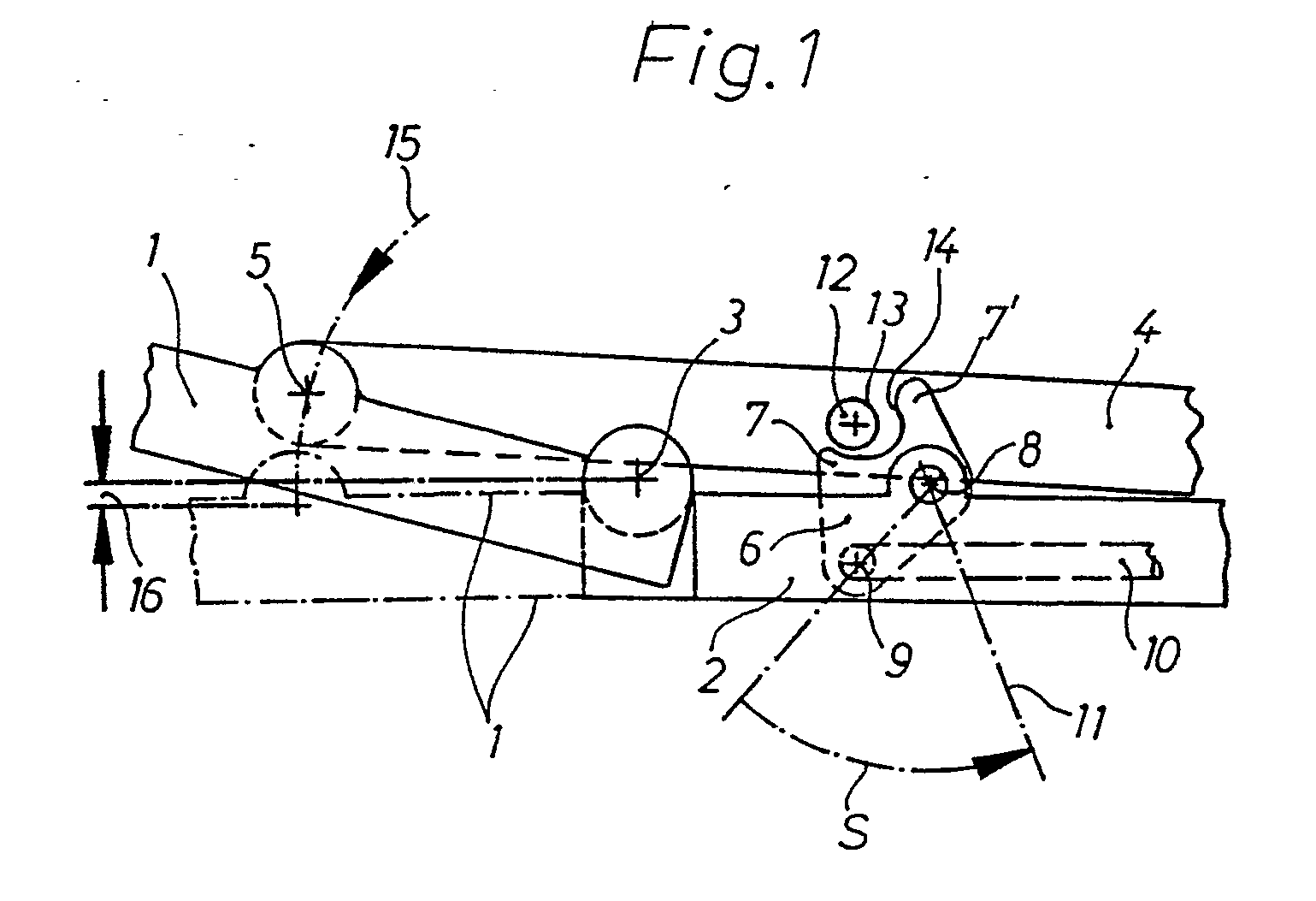
Description
Die Erfindung betrifft eine Verstelleinrichtung an einem Faltverdeck eines Kraftfahrzeugs, mit den im Oberbegriff des Patentanspruchs 1 angegebenen Merkmalen.The invention relates to an adjusting device on a folding top of a motor vehicle, with the features specified in the preamble of
Eine derartige Verstelleinrichtung ist bereits aus der DE-PS 885 356 bekannt, die an beiden Dachseiten jeweils an einem einen vorderen und hinteren Dachlenker verbindenden Gelenk einen Elektromotor aufweist, der ein selbsttätiges Öffnen und Schließen des Faltverdecks ermöglicht. Ein wesentlicher Nachteil dieser Verstelleinrichtung ist, daß der Elektromotor so auszulegen ist, daß er die beim Öffnen und Schließen des Faltverdecks maximal auftretenden Öffnungs- und Schließkräfte überwindet. Die Öffnungs- und Schließkräfte des Faltverdecks sind jedoch in Abhängigkeit von dem Verstellweg unterschiedlich, so daß der Elektromotor in den Verstellbereichen mit geringen Öffnungs- und Schließkräften überdimensioniert ist. Außerdem schränkt der Elektromotor bei geschlossenem Faltverdeck seitliche Kopfbewegungen einer auf der zugeordneten Fahrzeugseite im Fondraum sitzenden Person ein, wodurch sich die Verletzungsgefahr bei einem Unfall erhöht. Erforderlich ist auch eine lange Stromkabelzuführung an das Gelenk der Dachlenker, die beim Öffnen und Schließen des Faltverdecks abknickt und dadurch beschädigt werden kann.Such an adjustment device is already known from DE-PS 885 356, which has an electric motor on both roof sides at a joint connecting a front and rear roof link, which enables the folding top to be opened and closed automatically. A major disadvantage of this adjustment device is that the electric motor is to be designed so that it overcomes the maximum opening and closing forces that occur when the folding top is opened and closed. However, the opening and closing forces of the folding top are different depending on the adjustment path, so that the electric motor is oversized in the adjustment areas with low opening and closing forces. In addition, when the folding top is closed, the electric motor restricts lateral head movements of a person sitting in the rear area on the assigned vehicle side, which increases the risk of injury in the event of an accident. A long power cable feed to the joint of the roof handlebar is also required, which kinks when opening and closing the folding top and can be damaged as a result.
Der Erfindung liegt die Aufgabe zugrunde, eine Verstelleinrichtung an einem Faltverdeck eines Kraftfahrzeugs nach dem Oberbegriff des Patentanspruchs 1 anzugeben, die auf einfache Weise mit einem geringen Energiebedarf ein selbsttätiges Öffnen und/oder Schließen des Faltverdecks ermöglicht. Darüber hinaus soll die Verstelleinrichtung so anzuordnen sein, daß der Fahrgastraum des Kraftfahrzeugs durch die Verstelleinrichtung nicht oder nur unwesentlich eingeschränkt ist.The invention has for its object to provide an adjusting device on a folding top of a motor vehicle according to the preamble of
Diese Aufgabe ist durch die im Kennzeichen des Patentanspruchs 1 angegebenen Merkmale gelöst. Besonders vorteilhaft ist, daß mit dieser Verstelleinrichtung das Faltverdeck durch den Motorantrieb zwangsweise aus der Schließstellung und/oder aus einer Vorschließstellung in die Schließstellung des Faltverdecks verlagert werden kann. Hierzu ist lediglich ein einfaches, mit dem Motorantrieb in Verbindung stehendes Stellglied erforderlich, das sich beispielsweise zum Öffnen und Schließen des Faltverdecks an einer einfach zu bildenden Stützschulter an einem der Dachlenker oder an dem Lenker abstützt. Das Stellglied kann ein einfacher Schwenkhebel oder ein Schiebeelement und die Stützschulter ein Wandabschnitt an einem der Dachlenker oder an dem Lenker sein. Ebenso kann die Stützschulter durch einen Bolzen oder Zapfen gebildet sein, der von einem der Dachlenker oder dem Lenker absteht. Die Verstelleinrichtung eignet sich insbesondere für Faltverdecke, bei denen jeweils der seitlich vordere und hintere Dachlenker ein Übertotpunktgelenk bilden. Das Verdeckgestänge kann in einem vollautomatischen Bewegungsablauf von weiteren Antriebsmitteln aus der vollständig zurückgeschwenkten Offenstellung in eine Vorschließstellung gebracht und anschließend von der Verstelleinrichtung zwangsweise in die Schließstellung des Faltverdecks und umgekehrt in die Offenstellung verlagert werden. Durch das Zusam menwirken der weiteren Antriebsmittel mit der Verstelleinrichtung ist eine an die unterschiedlichen Öffnungs- und Schließkräfte angepaßte Auslegung der Antriebsmittel und der Verstelleinrichtung möglich, wodurch diese eine geringere Antriebsleistung erfordern. Die Verstelleinrichtung kann ohne weiteres so angeordnet werden, daß sie den Fahrgastraum ohne Vergrößerung des Fahrzeugs nicht oder nur unwesentlich einschränkt.This object is achieved by the features specified in the characterizing part of
Vorteilhafte Ausgestaltungen der Erfindung sind Gegenstand von Unteransprüchen.Advantageous embodiments of the invention are the subject of dependent claims.
Zwei Ausführungsbeispiele der Erfindung werden anhand einer Zeichnung näher erläutert. Es zeigen
- Fig. 1 ein erstes Ausführungsbeispiel in Seitenansicht, mit einem schwenkbaren Stellglied,
- Fig. 2 eine Fig. 1 entsprechende Ansicht in Schließstellung des Faltverdecks,
- Fig. 3 ein zweites Ausführungsbeispiel mit einem verschiebbaren Stellglied,
- Fig. 4 das Stellglied gemäß Fig. 3 in Vorschließstellung des Faltverdecks,
- Fig. 5 eine Seitenansicht von den beiden Dachlenkern und dem Lenker in Fig. 3,
- Fig. 6 eine Draufsicht auf eine die Lenker in Fig. 5 verbindende Tragbrücke und
- Fig. 7 eine Fig. 6 entsprechende Ansicht mit quer angeordnetem Motorantrieb.
- 1 shows a first embodiment in side view, with a pivotable actuator,
- 2 a view corresponding to FIG. 1 in the closed position of the folding top,
- 3 shows a second embodiment with a displaceable actuator,
- 4 the actuator according to FIG. 3 in the closed position of the folding top,
- 5 is a side view of the two roof links and the handlebar in Fig. 3,
- Fig. 6 is a plan view of a support bridge connecting the handlebars in Fig. 5 and
- Fig. 7 is a Fig. 6 corresponding view with a transversely arranged motor drive.
Das in Fig. l in einem ersten Ausführungsbeispiel nur teilweise in Seitenansicht dargestellte Verdeckgestänge trägt einen nicht dargestellten Verdeckstoff eines an einem Cabriolet-Kraftfahrzeug vorgesehenen Faltverdecks. Das Verdeckgestänge weist an beiden Dachseiten symmetrisch gegenüberliegend je einen vorderen Dachlenker 1 und einen hinteren Dachlenker 2 auf, die in einem Gelenk 3 um eine Querachse schwenkbar verbunden sind. Ein Lenker 4 greift in einem Gelenk 5 an einem Hebelarm des vorderen Dachlenkers 1 an. In Schließstellung des Faltverdecks verlaufen die Dachlenker 1, 2 und der Lenker 4 etwa in Fahrzeuglängsrichtung. Das Faltverdeck ist von nicht dargestellten Antriebsmitteln, beispielsweise hydraulischen Stellzylindern, in eine Vorschließstellung verlagerbar, in der sich die Dachlenker 1, 2 und der Lenker 4 in der in der Figur dargestellten Lage befinden. Eine mit einer nicht dargestellten Steuer- oder Regeleinrichtung zusammenwirkende Verstelleinrichtung ermöglicht ein weiteres, bei dem Ausführungsbeispiel vollautomatisches Schließen des Faltverdecks, bei dem der Verdeckstoff gespannt wird. Die Verstelleinrichtung weist bei dem Ausführungsbeispiel ein Stellglied 6 mit zwei Stützarmen 7, 7′ auf. Bei dem Ausführungsbeispiel ist das Stellglied 6 um eine Querachse 8 an dem hinteren Dachlenker 2 schwenkbar befestigt. Die beiden Stützarme 7, 7′ sind zur Querachse 8 etwa V-förmig angeordnet. An einem Hebelarm des Stellgliedes 6 greift in einem Gelenk 9 ein Stangenelement 10 an, das mit einem nicht dargestellten Motorantrieb in Verbindung steht. Ist der in entgegengesetzte Wirkrichtungen akivierbare Motorantrieb von der Steuer- oder Regeleinrichtung in einem dem weiteren Schließen des Faltverdecks entsprechenden Sinn beispielsweise beim Erreichen der Vorschließstellung selbsttätig oder über einen Schalter von Hand eingeschaltet, so schwenkt das Stellglied 6 in Pfeilrichtung S in die durch eine strichpunktierte Linie 11 gekennzeichnete Lage. Dabei wird der Lenker 4 über einen seitlich von dem Lenker 4 abstehenden Bolzen oder Zapfen 12, der eine Stützschulter 13 für eine Wirkfläche 14 an dem Stützarm 7′ bildet, an den hinteren Dachlenker 2 angenähert. Der vordere Dachlenker 1 wird dadurch in Pfeilrichtung 15 über eine Längslage, in der der vordere und hintere Dachlenker gestreckt sind, hinaus in eine Übertotpunktlage eingeschwenkt, in der das Faltverdeck geschlossen und der Verdeckstoff gespannt ist. In der dargestellten Übertotpunktlage liegt das Gelenk 5 etwa um den Abstand 16 tiefer als das Gelenk 3, so daß sich das Faltverdeck unter der Spannkraft des Verdeckstoffes auch dann nicht öffnen kann, wenn das Stellglied 6 in Schließstellung des Faltverdecks vor einer Verlagerung in eine Öffnungslage nicht gesichert ist. Der vordere Dachlenker könnte sich auch in Schließstellung des Faltverdecks in einer anderen als der angegebenen Lage befinden, die keine Übertotpunktlage ist, wenn das Verdeckgestänge in Schließstellung von dem mit einer Stützschulter zusammenwirkenden Stellglied beispielsweise durch Selbsthemmung des Motorantriebs zuverlässig festgehalten ist. Es ist auch möglich, daß das Stellglied an einem der Dachlenker oder an dem Lenker beispielsweise über ein Hebelgetriebe schwenkbar oder verschiebbar angeordnet ist. In diesem Fall ist die Stützschulter an dem anderen Teil, an dem Lenker oder an einem der Dachlenker, auszubilden. Die Stützschulter kann auch durch einen Wandabschnitt des Gelenks 3 gebildet sein, wenn das Stellglied an dem Lenker verlagerbar angeordnet ist.The convertible top linkage shown only partially in a side view in FIG. 1 carries a convertible top material, not shown, of a folding top provided on a convertible motor vehicle. The top linkage has a
Wird das Stellglied 6 aus der in Fig. 2 dargestellten Lage, die der Schließstellung des Faltverdecks entspricht, in Pfeilrichtung 0 bis in die durch die strichpunktierte Linie 17 dargestellte Lage verschwenkt, so verlagern sich durch das Zusammenwirken einer Wirk fläche 18 an dem Stellglied 6 mit dem Zapfen 12 die Dachlenker 1, 2 und der Lenker 4 in die in Fig. 1 dargestellte Vorschließstellung. Das weitere Öffnen des Faltverdecks kann nun von Hand oder wie in dem Ausführungsbeispiel durch die nicht dargestellten weiteren Antriebsmittel vollautomatisch erfolgen.If the
Bei dem in Fig. 3 dargestellten zweiten Ausführungsbeispiel ist ein Stellglied 6′ vorgesehen, das an einem die seitlich gegenüberliegenden Lenker 4′ verbindenden Träger 19 in Querrichtung verschiebbar angeordnet ist. Das Faltverdeck weist mit Ausnahme der nachfolgend beschriebenen Unterschiede einen dem Faltverdeck gemäß den Fig. 1 und 2 entsprechenden Aufbau auf, mit an beiden Fahrzeugseiten jeweils einem vorderen Dachlenker 1′, einem hinteren Dachlenker 2′ und einem an einem Hebelarm des vorderen Dachlenkers 1′ angreifenden Lenker 4′. Das Stellglied 6′ ist zum Öffnen des Faltverdecks aus einer durch eine unterbrochene Linie 20 gekennzeichneten zurückgezogenen Lage in die in der Figur durch die ausgezogene Linie 21 angegebene Entriegelungsstellung verlagert, in der eine am Stellglied 6′ ausgebildete Wirkfläche 22 mit einer Stützfläche am vorderen Dachlenker 1′ zusammenwirkt. Bei dem Ausführungsbeispiel ist die Stützschulter durch den unteren Rand 23 einer schlitzförmigen Öffnung 24 in einer im hinteren Bereich mit dem vorderen Dachlenker 1′ verbundenen Stützplatte gebildet. Durch die seitliche Stellbewegung des Stellgliedes 6′ wird der vordere Dachlenker 1′ gegenüber dem hinteren Dachlenker 2′ so aus einer der Schließstellung des Faltverdecks entsprechenden Übertotpunktlage verschwenkt, daß sich nach dem anschließenden Zurückziehen des Stellgliedes 6′ in die Lage 20 die Dachlenker 1′, 2′ selbsttätig unter der Spannkraft des Verdeckstoffes in eine nicht dargestellte, der Vorschließstellung entsprechende Offenstellung verlagern.In the second embodiment shown in Fig. 3, an actuator 6 'is provided, which is arranged on a laterally opposite link 4' connecting
Auch bei diesem Ausführungsbeispiel sind weitere, nicht dargestellte Antriebsmittel vorgesehen, die das Faltverdeck in einem vollautomatischen Öffnungsvorgang aus dieser Vorschließstellung in eine vollständig zurückgeschwenkte Öffnungsstellung verlagern.Also in this embodiment, further drive means, not shown, are provided, which move the folding top from this pre-closed position into a fully pivoted open position in a fully automatic opening process.
Ist in umgekehrter Weise das Faltverdeck von den nicht dargestellten weiteren Antriebsmitteln aus der vollständig zurückgeschwenkten Offenstellung in die in Fig. 4 dargestellte Vorschließstellung verlagert, so kann die beispielsweise selbsttätig aktivierte Verstelleinrichtung das Faltverdeck aus der Vorschließstellung in die Schließstellung verlagern, in der der Innenraum des Fahrzeugs von dem Faltverdeck wasserdicht überdeckt ist. Um diesen Schließvorgang zu bewirken, weist das Stellglied 6′ an seinem oberen Bereich eine weitere Wirkfläche 26 auf, die mit einer durch den oberen Rand der Öffnung 24 in der Stützplatte 25 gebildeten Stützschulter 27 zusammenwirkt. Wie man aus Fig. 3 erkennt, ist das Stützglied 6′ zum vollständigen Schließen des Faltverdecks bis in die durch die unterbrochene Linie 28 gekennzeichnete Lage in die Öffnung 24 einzuschieben, worauf sich die Dachlenker 1′, 2′ unter der Spannkraft des Verdeckstoffes selbsttätig in ihre durch ausgezogene Linien dargestellte, einer Übertotpunktstellung entsprechende Stellung verlagern, in der das Faltverdeck vollständig geschlossen ist. Wie man aus Fig. 4 weiter erkennt, ist der untere Bereich der Öffnung 24 um die Anlenkstelle 29 des Lenkers 4′ an dem vorderen Dachlenker 1′ gekrümmt, um einen seitlichen Freiraum zwischen dem in die Öffnung 24 eindringenden Stellglied 6′ und den Seitenwänden der Öffnung 24 sicherzustellen, wenn die Dachlenker aus der Vorschließstellung in die Schließstellung, und umgekehrt, verschwenken.Conversely, if the folding top is shifted from the further drive means, not shown, from the fully pivoted open position to the closing position shown in FIG. 4, the automatically activated adjustment device can shift the folding top from the closed position to the closed position, in which the interior of the vehicle is covered waterproof by the folding top. In order to effect this closing operation, the actuator 6 'has at its upper region a further
In der Darstellung gemäß Fig. 5 ist neben dem vorderen Dachlenker 1′, dem hinteren Dachlenker 2′ und dem Lenker 4′ eine obere Spannstange 30, ein Hauptlenker 31, eine Hauptsäule 32 und ein Hauptspriegel 33 erkennbar, an dem sich der Verdeckstoff 34 des Faltverdecks abstützt. Das Verdeckgestänge des Faltverdecks könnte aber auch anders mit einem vorderen und hinteren Dachlenker und einem Lenker gebildet sein.5 is next to the front roof link 1 ', the rear roof link 2' and the link 4 'an
Aus der in Fig. 6 angegebenen Draufsicht ist ersichtlich, daß bei dem Ausführungsbeispiel die seitlich gegenüberliegenden Lenker 4′, von denen aufgrund der Symmetrie zur vertikalen Längsmittelebene nur ein Lenker 4′ dargestellt ist, über den Träger 19 verbunden sind. Der Träger 19 kann wie bei dem Ausführungsbeispiel ein Blechteil sein. Ebenso läßt sich der Träger 19 aus einem anderen Material, beispielsweise aus Kunststoff, fertigen. Zur Gewichtseinsparung weist der Träger 19 Ausschnitte 35, 35′, 35˝ auf, die so angeordnet sind, daß die Steifigkeit des Trägers 19 erhalten bleibt. Der Träger 19 wirkt wie ein Überrollbügel, der die Fahrzeuginsassen bei einem Unfall schützt. An diesem ist ein durch einen doppelwirkenden hydraulischen Stellzylinder 36 gebildeter Motorantrieb mit entsprechend dem Doppelpfeil in Längsrichtung verstellbarer Kolbenstange 37 abgestützt. Der Motorantrieb könnte auch durch einen anderen Antrieb, beispielsweise durch einen hydraulisch einfachwirkenden oder einen pneumatisch einfach- oder doppelwirkenden Stellzylinder gebildet sein. Ebenso kann eine Elektromotor Verwendet werden. Zur Übertragung der Bewegung der Kolbenstange 37 auf das Stellglied 6′ dient bei dem Ausführungsbeispiel eine in Querrichtung verlaufenede Stellstange 38, die einerseits gelenkig mit dem Stellglied 6′ und andererseits gelenkig mit einem Arm eines zweiarmigen Winkelhebels 39 verbunden ist, der schwenkbar an dem Träger 19 abgestützt ist. An dem freien Schenkelende des Winkelhebels 39 ist ein Übertragungshebel 40 angelenkt, der mit dem vorstehenden Ende der Kolbenstange 37 gelenkig verbunden ist. Durch diese Anordnung des Stellzylinders 36 und der Übertragungselemente ist der Motorantrieb unauffällig und verletzungssicher untergebracht. Der Fahrgastraum oder die Bauweise des Faltverdecks wird nicht oder kaum eingeschränkt. Eine Bewegungsübertragung von der Kolbenstange 37 auf das Stellglied 6′ kann auch anders, beispielsweise über ein oder mehrere Seile erfolgen. Ist wie bei dem zweiten Ausführungsbeispiel ein verschiebbares Stellglied 6′ vorgesehen, so kann dieses in Querrichtung oder in einer anderen Richtung, beispielsweise in Längsrichtung, an dem Lenker 4′ oder an dem vorderen oder hinteren Dachlenker verstellbar angeordnet sein.From the top view shown in Fig. 6 it can be seen that in the embodiment, the laterally opposite link 4 ', of which only one link 4' is shown due to the symmetry to the vertical longitudinal median plane, are connected via the
Eine mögliche Variante zu dem zweiten Ausführungsbeispiel ist in Fig. 7 abgebildet, mit einem Stellzylinder 36, der an einem mit dem Träger 19 vergleichbaren Träger 19′, mit in Querrichtung verstellbarer Kolbenstange 37 abgestützt ist. Das vorstehende Ende der Kolbenstange 37 greift gelenkig an einem gestreckt zweiarmigen Schwenkhebel 41 an, der etwa in Fahrzeuglängsrichtung verläuft und um eine vertikale Achse 42 schwenkbar an dem Träger 19′ abgestützt ist. Symmetrisch zur Achse 42 greifen an dem Schwenkhebel jeweils eine Stellstange 37′, 37˝ an, die jeweils gelenkig mit einem zugeordneten Stellglied 6′ verbunden sind.A possible variant of the second embodiment is shown in Fig. 7, with an
Bei den Ausführungsbeispielen wurden schwenkbare bzw. verschiebbare Stellglieder verwendet, die zwangsweise ein Öffnen des Faltverdecks aus der Schließstellung und ein vollständiges Schließen aus einer Vorschließstellung bewirken. Ebenso könnten Stellglieder vorgesehen sein, die nur ein Schließen oder aber nur ein Öffnen des Faltverdecks bewirken, beispielsweise wenn das Faltverdeck nur in eine der angegebenen Richtungen schwer zu verstellen ist. Ohne den Erfindungsgedanken zu verlassen, kann für das Schließen des Faltverdecks und für das Öffnen des Faltverdecks beispielsweise auf beiden Fahrzeugseiten jeweils ein eigenes, schwenkbares oder verschiebbares Stellglied vorgesehen sein. Das Stellglied kann wie bei dem ersten Ausführungsbeispiel eine Arretierung der Dachlenker und des Lenkers bewirken, wenn das Faltverdeck geschlossen ist. Bei dem zweiten Ausführungsbeispiel gemäß Fig. 3 ist zwar keine derartige Verriegelung vorgesehen, doch kann mit dem angegebenen oder einem ähnlichen Stellglied auch bei dieser Ausfühung eine Arretierung der Dachlenker und des Lenkers in Schließstellung des Faltverdecks erreicht werden, wodurch sich die Sicherheit vor einem unbeabsichtigten Öffnen des Faltverdecks bei einem Unfall erhöht. Der Motorantrieb kann wie bei den Ausführungsbeispielen als zentraler Antrieb ausgebildet sein, der beispielsweise zwei seitlich gegenüberliegenden Stellgliedern zugeordnet ist. Ebenso kann jedem Stellglied ein beispielsweise seitlich angeordneter Motorantrieb oder bei mehr als zwei Stellgliedern beispielsweise jeweils zwei Stellgliedern ein eigener Motorantrieb zugeordnet sein. Ist ein verschiebbares Stellglied vorgesehen, so kann dieses an dem mit der Stützschulter zusammenwirkenden Ende mit einem drehbaren Gleitrad versehen sein, um die zwischen dem Stellglied und der Stützschulter auftretenden Reibkräfte zu vermindern.In the exemplary embodiments, pivotable or displaceable actuators were used, which inevitably bring about an opening of the folding top from the closed position and a complete closing from a pre-closed position. Actuators could also be provided that only close or open the Folding hoods cause, for example, if the folding hood is difficult to adjust only in one of the specified directions. Without leaving the concept of the invention, a separate, pivotable or displaceable actuator can be provided for closing the folding top and for opening the folding top, for example, on both sides of the vehicle. As in the first exemplary embodiment, the actuator can lock the roof link and the link when the folding top is closed. In the second embodiment according to FIG. 3, no such locking is provided, but with the specified or a similar actuator, even with this embodiment, the roof handlebars and the handlebars can be locked in the closed position of the folding top, which increases the security against unintentional opening the folding top in the event of an accident. As in the exemplary embodiments, the motor drive can be designed as a central drive which is assigned, for example, to two actuators located opposite one another. Likewise, each actuator can be assigned, for example, a laterally arranged motor drive or, in the case of more than two actuators, two actuators, for example, a separate motor drive. If a displaceable actuator is provided, this can be provided with a rotatable sliding wheel at the end cooperating with the support shoulder in order to reduce the frictional forces occurring between the actuator and the support shoulder.
Claims (11)
Applications Claiming Priority (2)
| Application Number | Priority Date | Filing Date | Title |
|---|---|---|---|
| DE3917284 | 1989-05-27 | ||
| DE19893917284 DE3917284C2 (en) | 1989-05-27 | 1989-05-27 | Adjustment device on a folding roof of a motor vehicle |
Publications (3)
| Publication Number | Publication Date |
|---|---|
| EP0400376A2 true EP0400376A2 (en) | 1990-12-05 |
| EP0400376A3 EP0400376A3 (en) | 1992-06-24 |
| EP0400376B1 EP0400376B1 (en) | 1994-07-13 |
Family
ID=6381510
Family Applications (1)
| Application Number | Title | Priority Date | Filing Date |
|---|---|---|---|
| EP19900108883 Expired - Lifetime EP0400376B1 (en) | 1989-05-27 | 1990-05-11 | Adjusting flexible hood device for a motor vehicle |
Country Status (3)
| Country | Link |
|---|---|
| EP (1) | EP0400376B1 (en) |
| DE (1) | DE3917284C2 (en) |
| ES (1) | ES2057255T3 (en) |
Cited By (2)
| Publication number | Priority date | Publication date | Assignee | Title |
|---|---|---|---|---|
| US5286077A (en) * | 1992-03-05 | 1994-02-15 | Oy Saab-Valmet Ab | Top mechanism for the retractable top of an open automobile |
| EP0699549A1 (en) * | 1994-08-28 | 1996-03-06 | Jeroen Van Bon | Folding roof for motorvehicle |
Families Citing this family (7)
| Publication number | Priority date | Publication date | Assignee | Title |
|---|---|---|---|---|
| DE4111646C2 (en) * | 1991-04-10 | 1994-12-08 | Bayerische Motoren Werke Ag | Locking device, in particular for a convertible folding top |
| DE4415969C2 (en) * | 1994-05-08 | 2002-05-16 | Scharwaechter Gmbh Co Kg | Closure drive for a folding roof of a motor vehicle |
| DE29711049U1 (en) * | 1997-06-25 | 1998-11-19 | Wilhelm Karmann GmbH, 49084 Osnabrück | Cabriolet vehicle |
| DE10218307B4 (en) | 2002-04-24 | 2007-10-18 | Webasto Ag | Roof construction for a convertible |
| DE102004040697B4 (en) * | 2004-08-23 | 2006-09-07 | Edscha Cabrio-Dachsysteme Gmbh | top linkage |
| DE102004044908B3 (en) | 2004-09-14 | 2006-06-14 | Wilhelm Karmann Gmbh | Convertible car |
| DE102006030517A1 (en) * | 2006-07-01 | 2008-01-03 | Wilhelm Karmann Gmbh | Cabriolet vehicle for operating a moving roof has a roof with multiple roof sections held on side frame parts to be repositioned against each other |
Family Cites Families (4)
| Publication number | Priority date | Publication date | Assignee | Title |
|---|---|---|---|---|
| DE885356C (en) * | 1941-07-22 | 1953-08-03 | Auto Union A G | Folding top for motor vehicles |
| DE2327486C2 (en) * | 1973-05-30 | 1975-04-30 | Daimler-Benz Ag, 7000 Stuttgart | Control of a linkage of a folding top of motor vehicles that is hinged to sunk-in consoles |
| DE3724532C1 (en) * | 1987-07-24 | 1988-11-10 | Daimler Benz Ag | Hood frame of a folding roof for vehicles |
| DE3901051A1 (en) * | 1988-03-31 | 1989-10-19 | Daimler Benz Ag | SWIVELING ASSISTANCE OF A ROOF SKIN BRACKET THAT MAKES THE LOWER ENCLOSURE OF A FOLDING COVER |
-
1989
- 1989-05-27 DE DE19893917284 patent/DE3917284C2/en not_active Expired - Lifetime
-
1990
- 1990-05-11 EP EP19900108883 patent/EP0400376B1/en not_active Expired - Lifetime
- 1990-05-11 ES ES90108883T patent/ES2057255T3/en not_active Expired - Lifetime
Cited By (2)
| Publication number | Priority date | Publication date | Assignee | Title |
|---|---|---|---|---|
| US5286077A (en) * | 1992-03-05 | 1994-02-15 | Oy Saab-Valmet Ab | Top mechanism for the retractable top of an open automobile |
| EP0699549A1 (en) * | 1994-08-28 | 1996-03-06 | Jeroen Van Bon | Folding roof for motorvehicle |
Also Published As
| Publication number | Publication date |
|---|---|
| DE3917284A1 (en) | 1990-11-29 |
| DE3917284C2 (en) | 1998-03-19 |
| EP0400376B1 (en) | 1994-07-13 |
| ES2057255T3 (en) | 1994-10-16 |
| EP0400376A3 (en) | 1992-06-24 |
Similar Documents
| Publication | Publication Date | Title |
|---|---|---|
| DE19944615C2 (en) | Lock for a swiveling motor vehicle roof | |
| DE10205144B4 (en) | Locking device for a folding roof of a vehicle | |
| EP0754130A1 (en) | Locking device for detachably securing a vehicle roof to an immovable part of the car body | |
| EP0222160A2 (en) | Operating device for a freight-loading door | |
| DE3923695C2 (en) | Device for pulling down the front end of a vehicle top | |
| EP0933242B1 (en) | Driving device for vehicle top | |
| DE10160406B4 (en) | Hood compartment in a convertible vehicle for receiving an openable vehicle roof | |
| DE60133543T2 (en) | VERSATILE RIGGED ROOF SYSTEM FOR CABRIO VEHICLES | |
| EP1314601B1 (en) | Openable vehicle roof with a folding top | |
| EP1108582B1 (en) | Device for locking two guided elements displaceable to each other | |
| EP0400376B1 (en) | Adjusting flexible hood device for a motor vehicle | |
| DE10259864A1 (en) | Cabriolet vehicle with a movable roof | |
| EP1554150B1 (en) | Hood compartment cover for a cabriolet vehicle with a retractable hood | |
| DE3400753A1 (en) | Outer swing door for vehicles, and its actuating device | |
| EP1034979B1 (en) | Rear window shelf for vehicles with folding top | |
| EP1554151B1 (en) | Cabriolet vehicle with a hood compartment which receives the cabriolet hood | |
| DE19812835B4 (en) | Fanghook actuator assembly for engine hoods of motor vehicles | |
| DE102017121577A1 (en) | Top compartment lid assembly with control arms and drive link assembly | |
| EP1907231A2 (en) | Drive unit of a movable vehicle component | |
| DE10052001A1 (en) | Convertible has hatchback, which can be raised at back to allow luggage to be put in or at front to allow roof to be moved under it, on lever system comprising section attached to hatchback and section attached to auxiliary frame component | |
| EP1132241A2 (en) | Convertible vehicle with a foldable top storable underneath a cover panel of a foldable top compartment | |
| DE202015004325U1 (en) | Locking device for one or more nose flaps, in particular for rail vehicles | |
| DE9309760U1 (en) | Motor vehicle | |
| DE19511013A1 (en) | Locking arrangement for motorcycle cases | |
| DE10161394B4 (en) | Roof kinematics for a hardtop vehicle roof with at least two rigid roof parts |
Legal Events
| Date | Code | Title | Description |
|---|---|---|---|
| PUAI | Public reference made under article 153(3) epc to a published international application that has entered the european phase |
Free format text: ORIGINAL CODE: 0009012 |
|
| AK | Designated contracting states |
Kind code of ref document: A2 Designated state(s): ES FR GB IT |
|
| PUAL | Search report despatched |
Free format text: ORIGINAL CODE: 0009013 |
|
| AK | Designated contracting states |
Kind code of ref document: A3 Designated state(s): ES FR GB IT |
|
| 17P | Request for examination filed |
Effective date: 19920523 |
|
| RAP3 | Party data changed (applicant data changed or rights of an application transferred) |
Owner name: BAYERISCHE MOTOREN WERKE AKTIENGESELLSCHAFT |
|
| 17Q | First examination report despatched |
Effective date: 19930928 |
|
| GRAA | (expected) grant |
Free format text: ORIGINAL CODE: 0009210 |
|
| AK | Designated contracting states |
Kind code of ref document: B1 Designated state(s): ES FR GB IT |
|
| ET | Fr: translation filed | ||
| GBT | Gb: translation of ep patent filed (gb section 77(6)(a)/1977) |
Effective date: 19940725 |
|
| ITF | It: translation for a ep patent filed | ||
| REG | Reference to a national code |
Ref country code: ES Ref legal event code: FG2A Ref document number: 2057255 Country of ref document: ES Kind code of ref document: T3 |
|
| PLBE | No opposition filed within time limit |
Free format text: ORIGINAL CODE: 0009261 |
|
| STAA | Information on the status of an ep patent application or granted ep patent |
Free format text: STATUS: NO OPPOSITION FILED WITHIN TIME LIMIT |
|
| 26N | No opposition filed | ||
| PGFP | Annual fee paid to national office [announced via postgrant information from national office to epo] |
Ref country code: GB Payment date: 19970506 Year of fee payment: 8 |
|
| PGFP | Annual fee paid to national office [announced via postgrant information from national office to epo] |
Ref country code: ES Payment date: 19970514 Year of fee payment: 8 |
|
| PGFP | Annual fee paid to national office [announced via postgrant information from national office to epo] |
Ref country code: FR Payment date: 19970530 Year of fee payment: 8 |
|
| PG25 | Lapsed in a contracting state [announced via postgrant information from national office to epo] |
Ref country code: GB Free format text: LAPSE BECAUSE OF NON-PAYMENT OF DUE FEES Effective date: 19980511 |
|
| PG25 | Lapsed in a contracting state [announced via postgrant information from national office to epo] |
Ref country code: ES Free format text: LAPSE BECAUSE OF NON-PAYMENT OF DUE FEES Effective date: 19980512 |
|
| PG25 | Lapsed in a contracting state [announced via postgrant information from national office to epo] |
Ref country code: FR Free format text: LAPSE BECAUSE OF NON-PAYMENT OF DUE FEES Effective date: 19980531 |
|
| GBPC | Gb: european patent ceased through non-payment of renewal fee |
Effective date: 19980511 |
|
| REG | Reference to a national code |
Ref country code: FR Ref legal event code: ST |
|
| REG | Reference to a national code |
Ref country code: ES Ref legal event code: FD2A Effective date: 20000503 |
|
| PG25 | Lapsed in a contracting state [announced via postgrant information from national office to epo] |
Ref country code: IT Free format text: LAPSE BECAUSE OF NON-PAYMENT OF DUE FEES;WARNING: LAPSES OF ITALIAN PATENTS WITH EFFECTIVE DATE BEFORE 2007 MAY HAVE OCCURRED AT ANY TIME BEFORE 2007. THE CORRECT EFFECTIVE DATE MAY BE DIFFERENT FROM THE ONE RECORDED. Effective date: 20050511 |