EP0406448A1 - Dispositif detecteur de temperature anormale d'une resistance de regeneration - Google Patents
Dispositif detecteur de temperature anormale d'une resistance de regeneration Download PDFInfo
- Publication number
- EP0406448A1 EP0406448A1 EP90901678A EP90901678A EP0406448A1 EP 0406448 A1 EP0406448 A1 EP 0406448A1 EP 90901678 A EP90901678 A EP 90901678A EP 90901678 A EP90901678 A EP 90901678A EP 0406448 A1 EP0406448 A1 EP 0406448A1
- Authority
- EP
- European Patent Office
- Prior art keywords
- temperature
- regeneration resistor
- thermostat
- conductive member
- resistor
- Prior art date
- Legal status (The legal status is an assumption and is not a legal conclusion. Google has not performed a legal analysis and makes no representation as to the accuracy of the status listed.)
- Withdrawn
Links
- 230000002159 abnormal effect Effects 0.000 title claims abstract description 23
- 230000001172 regenerating effect Effects 0.000 title claims abstract description 15
- 230000008929 regeneration Effects 0.000 claims abstract description 59
- 238000011069 regeneration method Methods 0.000 claims abstract description 59
- 238000001816 cooling Methods 0.000 claims description 22
- 238000001514 detection method Methods 0.000 claims description 9
- 239000002184 metal Substances 0.000 claims description 5
- 238000010586 diagram Methods 0.000 description 4
- 230000000694 effects Effects 0.000 description 3
- 230000002950 deficient Effects 0.000 description 2
- 239000000428 dust Substances 0.000 description 2
- 230000020169 heat generation Effects 0.000 description 2
- 238000009413 insulation Methods 0.000 description 2
- 230000005855 radiation Effects 0.000 description 2
- 239000004568 cement Substances 0.000 description 1
- 239000000919 ceramic Substances 0.000 description 1
- 238000011109 contamination Methods 0.000 description 1
- 230000007547 defect Effects 0.000 description 1
- 230000002708 enhancing effect Effects 0.000 description 1
- 238000000034 method Methods 0.000 description 1
- 239000010445 mica Substances 0.000 description 1
- 229910052618 mica group Inorganic materials 0.000 description 1
- 238000007493 shaping process Methods 0.000 description 1
- 229910000679 solder Inorganic materials 0.000 description 1
Images

Classifications
-
- G—PHYSICS
- G01—MEASURING; TESTING
- G01W—METEOROLOGY
- G01W1/00—Meteorology
- G01W1/16—Measuring atmospheric potential differences, e.g. due to electrical charges in clouds
-
- G—PHYSICS
- G01—MEASURING; TESTING
- G01K—MEASURING TEMPERATURE; MEASURING QUANTITY OF HEAT; THERMALLY-SENSITIVE ELEMENTS NOT OTHERWISE PROVIDED FOR
- G01K1/00—Details of thermometers not specially adapted for particular types of thermometer
- G01K1/16—Special arrangements for conducting heat from the object to the sensitive element
Definitions
- This invention relates to an abnormal temperature detection device for a regeneration resistor which processes the regenerative energy of an electric motor or the like by heat generation, and more particularly, to an abnormal temperature detection device for a regeneration resistor in a small-sized spindle motor, servomotor or the like used in an NC machine tool or industrial robot.
- a regeneration resistor is mounted on a small-sized spindle motor, servomotor or the like used in an NC machine tool or industrial robot, to consume a regenerative energy thereof.
- the regeneration resistor is covered with cement and set into a metal case, to thereby increase the surface area of the regeneration resistor so as to suppress a rise in the temperature thereof, and a thermostat is mounted on the surface thereof, whereby when an abnormal increase of the temperature of the regeneration resistor occurs, the abnormal temperature is detected and a countermeasure is taken by, for example, turning off the power source of the numerical control device.
- the regeneration resistor is constituted by only a resistor and a case, and an insulation member for isolating these members from each other, to reduce the overall size thereof, the surface temperature of the regeneration resistor is as high as several hundred °C even during a normal operation. Therefore, if a thermostat which is generally used at such high temperatures is set in direct contact with the regeneration resistor, the solder therein may be melted or the metal portion thereof oxidized.
- the regeneration resistor is forcibly air- cooled by a cooling fan, to suppress any rise in the temperature of the regeneration resistor, and therefore, a defect in the insulation in the thermostat may be easily caused by dust in the duct, making it difficult to correctly detect the temperature of the regeneration resistor.
- This invention has been made in view of the above circumstances, and an object thereof is to provide an abnormal temperature detection device for a regeneration resistor in which a thermostat able to detect temperatures of approximately 100°C is used to detect temperatures higher than approximately 100°C.
- an abnormal temperature detection device for a regeneration resistor for consuming the regenerative energy of an electric motor characterized by comprising a heat conductive member mounted in contact with the surface of the regeneration resistor and a thermostat for detecting a temperature rise due to an abnormal heat generation in the regeneration resistor, via the heat conductive member, and characterized in that the thermostat and the regeneration resistor are provided in different spaces.
- the surface temperature of the regeneration resistor which is set high, is not directly detected, and the thermostat is mounted on a portion at which the temperature is lowered via the heat conductive member and the temperature of the portion is detected.
- a thermostat able to detect temperatures of approximately 100°C can be used to detect temperatures higher than approximately 100°C, thereby making it possible to detect an abnormal heat generated in the regeneration resistor.
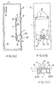
- FIGs 1(a) to 1(c) are diagrams showing an embodiment of this invention, wherein a regeneration resistor 1 is set inside a container (duct) constituted by a bottom plate 2 and an outer casing 3.
- the outer casing 3 is omitted.
- a cooling fan 4 and an air inlet port 5 are provided in the outer casing 3, and a rotation of the cooling fan 4 causes external cool air to be introduced via the air inlet port 5, to absorb the heat of the regeneration resistor 1, and to be discharged to the exterior via the cooling fan 4.
- a wiring 6 for a flow of regenerative current is connected to the regeneration resistor 1.
- the wiring 6 penetrates the bottom plate 2 and is lead out to the exterior of the duct, and one end of the regeneration resistor 1 is fixed to the bottom plate 2 by a fitting 7.
- the fitting 7 and bottom plate 2 are fixed together by a screw 8, and the fitting 7 and regeneration resistor 1 are fixed together by a screw 9.
- a heat insulating member 10 is disposed between the fitting 7 and regeneration resistor 1, to prevent a transfer of heat from the regeneration resistor 1 to the bottom plate 2, and mica, ceramic or the like can be used for the heat insulating member 10.
- the other end of the regeneration resistor 1 is fixed to the bottom plate 2 by a heat conductive member 11.
- the heat conductive member 11 is formed by shaping a rectangular metal plate to a concave configuration, and a thermostat 12 is mounted on an upper part of a concave portion of the heat conductive member 11.
- the thermostat 12 is projected toward the exterior of the duct, via an opening 13 of the bottom plate 2, and a portion thereof on the side of the opening 13 extends toward a not shown locker. Namely, the thermostat 12 and the regeneration resistor 1 are disposed in different containers (different spaces).
- the heat conductive member 11 and bottom plate 2 are fixed together by a screw 14, and the heat conductive member 11 is placed in contact with the surface of the regeneration resistor 1 and fixed thereto by a screw 15.
- a heat insulating member may be disposed between the heat conductive member 11 and the bottom plate 2.
- the temperature of the heat conductive member 11 mounted on the surface of the regeneration resistor 1 is adequately lowered by an air flow by the cooling fan 4. Therefore, the temperature of a portion on which the thermostat 12 is mounted becomes lower than the operation temperature of the thermostat 12, and thus a thermostat able to detect temperatures of approximately 100°C can be used to detect temperatures higher than approximately 100°C.
- Fig. 2 shows a heat radiation characteristic obtained when a regeneration resistor having a resistance of 16 ⁇ is used in this embodiment.
- the abscissa indicates a regenerative heat amount (W) given to the regeneration resistor and the ordinate indicates a rise in the temperature of the regeneration resistor, the indicated temperatures being measured with the ambient temperature and a temperature in the locker set to a reference temperature (0°C).
- a curve C1 indicates a rise in the temperature of the regeneration resistor itself when the operation of the cooling fan 4 is stopped and a natural cooling is effected
- a curve C2 indicates a rise in the temperature of the regeneration resistor itself when the cooling fan 4 is operated to effect a forced cooling operation at a wind speed of 5 meter/sec.
- the temperature of the regeneration resistor 1 becomes higher than 100°C even when the forced cooling operation is effected, at a regenerative heat amount of 200 W, and the temperature thereof becomes higher than 200°C when the operation of the cooling fan is interrupted and the natural cooling operation is effected.
- the range of the rise in the temperature of the thermostat is approximately 50°C at most, even when the regenerative heat amount is 500 W, and therefore, a thermostat able to detect temperatures of approximately 100°C or less than 100°C can be satisfactorily used to detect an abnormal temperature rise in the regeneration resistor. Further, an actual temperature of the regeneration resistor can be derived by effecting a converting operation based on the characteristic diagram of Fig. 2.
- the abnormal temperature rise caused by a continuous flow of an excessively large current due to a defective transistor of a control circuit for controlling a current in the regeneration resistor or an abnormal temperature rise caused by an interruption of the cooling fan for forcibly cooling the regeneration resistor, can be detected by the thermostat, and a countermeasure can be taken by, for example, turning off the power source of the device.
- the heat conductive member in this embodiment, but any other heat conductive member can be used.
- the shape of the heat conductive member is determined by taking into consideration the temperature of the regeneration resistor, the reduction in the temperature by the air-cooling of the fan, and the temperature detected by the thermostat, an abnormal rise in the temperature of the regeneration resistor can be detected by using a general thermostat for normal temperatures.
- the thermostat and the regeneration resistor are disposed in different spaces, and in particular, the thermostat is disposed in a tightly sealed locker, so that a contamination due to dust can be prevented, thereby enhancing the reliability of the thermostat itself.
- an effect can be obtained such that an abnormal temperature of the regeneration resistor set at temperatures higher than approximately 100°C can be detected by using a thermostat able to detect temperatures of approximately 100°C.
Landscapes
- Environmental & Geological Engineering (AREA)
- Physics & Mathematics (AREA)
- General Physics & Mathematics (AREA)
- Engineering & Computer Science (AREA)
- Life Sciences & Earth Sciences (AREA)
- Atmospheric Sciences (AREA)
- Biodiversity & Conservation Biology (AREA)
- Ecology (AREA)
- Environmental Sciences (AREA)
- Stopping Of Electric Motors (AREA)
- Measuring Temperature Or Quantity Of Heat (AREA)
- Thermally Actuated Switches (AREA)
Abstract
Dispositif servant à détecter la température anormale d'une résistance de régénération qui dissipe l'énergie de régénération d'un moteur électrique. Ce dispositif comporte un organe thermoconducteur (11) en contact avec la surface d'une résistance de régénération (1), ainsi qu'un thermostat (12) servant à détecter par l'intermédiaire de l'organe thermoconducteur une augmentation de température, provoquée par un dégagement anormal de chaleur par la résistance de régénération (1). Le thermostat (12) et la résistance de régénération (1) sont situés à des endroits différents. Ce dispositif n'est pas utilisé pour détecter directement la température de la surface de la résistance de régénération (1) à haute température. Le thermostat (12) est fixé sur une partie dont la température est abaissée par l'organe thermoconducteur (11), et on détecte la température de cette partie. Cet agencement permet de détecter les condiditons de température élevée de la résistance de régénération (1) à l'aide du thermostat (12) qui possède des caractéristiques de détection de faible température.
Applications Claiming Priority (2)
| Application Number | Priority Date | Filing Date | Title |
|---|---|---|---|
| JP1014625A JPH02197278A (ja) | 1989-01-24 | 1989-01-24 | 回生抵抗の異常温度検出装置 |
| JP114625/89 | 1989-01-24 |
Publications (1)
| Publication Number | Publication Date |
|---|---|
| EP0406448A1 true EP0406448A1 (fr) | 1991-01-09 |
Family
ID=11866387
Family Applications (1)
| Application Number | Title | Priority Date | Filing Date |
|---|---|---|---|
| EP90901678A Withdrawn EP0406448A1 (fr) | 1989-01-24 | 1990-01-10 | Dispositif detecteur de temperature anormale d'une resistance de regeneration |
Country Status (4)
| Country | Link |
|---|---|
| US (1) | US5164572A (fr) |
| EP (1) | EP0406448A1 (fr) |
| JP (1) | JPH02197278A (fr) |
| WO (1) | WO1990008947A1 (fr) |
Cited By (1)
| Publication number | Priority date | Publication date | Assignee | Title |
|---|---|---|---|---|
| EP0952764A3 (fr) * | 1998-04-21 | 2000-04-26 | Fanuc Ltd | Résistance pour un variateur et variateur avec cette résistance |
Families Citing this family (4)
| Publication number | Priority date | Publication date | Assignee | Title |
|---|---|---|---|---|
| JP2009149232A (ja) * | 2007-12-21 | 2009-07-09 | Nishishiba Electric Co Ltd | 船舶用電動機駆動システム |
| JP2010231730A (ja) * | 2009-03-30 | 2010-10-14 | Suzuki Gokin Kk | 高温警報表示器 |
| JP7006169B2 (ja) * | 2017-11-20 | 2022-01-24 | セイコーエプソン株式会社 | ロボット |
| JP6918741B2 (ja) * | 2018-04-27 | 2021-08-11 | 株式会社クボタ | 作業装置及びこの作業装置を備えた作業機 |
Family Cites Families (7)
| Publication number | Priority date | Publication date | Assignee | Title |
|---|---|---|---|---|
| JPS505947U (fr) * | 1973-05-11 | 1975-01-22 | ||
| JPS5256113U (fr) * | 1975-10-21 | 1977-04-22 | ||
| JPS56171547U (fr) * | 1980-05-22 | 1981-12-18 | ||
| JPS57171547U (fr) * | 1981-04-23 | 1982-10-28 | ||
| JPS6080796U (ja) * | 1983-11-09 | 1985-06-05 | 三洋電機株式会社 | 衣類乾燥機 |
| JPS611801U (ja) * | 1984-06-11 | 1986-01-08 | フアナツク株式会社 | 過熱検出器付回生抵抗器 |
| JPH0639345Y2 (ja) * | 1987-07-10 | 1994-10-12 | 和光電気株式会社 | 半導体の温度検出装置 |
-
1989
- 1989-01-24 JP JP1014625A patent/JPH02197278A/ja active Pending
-
1990
- 1990-01-10 US US07/571,648 patent/US5164572A/en not_active Expired - Fee Related
- 1990-01-10 EP EP90901678A patent/EP0406448A1/fr not_active Withdrawn
- 1990-01-10 WO PCT/JP1990/000026 patent/WO1990008947A1/fr not_active Ceased
Non-Patent Citations (1)
| Title |
|---|
| See references of WO9008947A1 * |
Cited By (2)
| Publication number | Priority date | Publication date | Assignee | Title |
|---|---|---|---|---|
| EP0952764A3 (fr) * | 1998-04-21 | 2000-04-26 | Fanuc Ltd | Résistance pour un variateur et variateur avec cette résistance |
| US6313974B1 (en) | 1998-04-21 | 2001-11-06 | Fanuc Ltd. | Resistor for a servo amplifier and servo amplifier provided thereof |
Also Published As
| Publication number | Publication date |
|---|---|
| JPH02197278A (ja) | 1990-08-03 |
| WO1990008947A1 (fr) | 1990-08-09 |
| US5164572A (en) | 1992-11-17 |
Similar Documents
| Publication | Publication Date | Title |
|---|---|---|
| CN1625038B (zh) | 冷冻装置和逆变装置 | |
| KR20200128690A (ko) | 스마트 배전함 | |
| JP2009540550A (ja) | 個々のソーラーパネルの過熱保護のための接続ボックス | |
| US20020038795A1 (en) | Power supply apparatus | |
| US5164572A (en) | Abnormal temperature detection device for regeneration resistor | |
| CN202488952U (zh) | 一种柜体用散热装置 | |
| EP0641024A2 (fr) | Dispositif semi-conducteur de puissance | |
| JP5056093B2 (ja) | 電気機器 | |
| JPH02232534A (ja) | サーボアンプの異常温度検出装置 | |
| CN115723579A (zh) | 一种矿用卡车电阻栅电气故障判断系统 | |
| CN212552407U (zh) | 一种在线式带保护结构的芯片真空可靠性封装焊接装置 | |
| CN115515379A (zh) | 电力电子冷却系统及方法 | |
| JPH07249944A (ja) | 電力増幅器の保護装置 | |
| CN214372555U (zh) | 一种散热型传感器 | |
| CN221948645U (zh) | 一种电力工程用取电设备 | |
| CN213906059U (zh) | 电气自动化控制的散热电气柜 | |
| CN115579775B (zh) | 一种用于配电柜的节能型空气调节系统 | |
| CN111782011A (zh) | 一种存储服务器主板断电保护装置 | |
| CN223539562U (zh) | 设备前端模块及半导体工艺设备 | |
| CN211240564U (zh) | 一种电气工程用的过热防护装置 | |
| CN219590431U (zh) | 一种非侵入式变压器在线监测设备 | |
| CN221378552U (zh) | 一种传感器恒温系统 | |
| JPH0675643A (ja) | 温度保護方法 | |
| CN113556926B (zh) | 半导体工艺设备及其冷却组件、冷却方法 | |
| JPH0834074B2 (ja) | プロテクタ |
Legal Events
| Date | Code | Title | Description |
|---|---|---|---|
| PUAI | Public reference made under article 153(3) epc to a published international application that has entered the european phase |
Free format text: ORIGINAL CODE: 0009012 |
|
| 17P | Request for examination filed |
Effective date: 19901011 |
|
| AK | Designated contracting states |
Kind code of ref document: A1 Designated state(s): DE FR GB |
|
| STAA | Information on the status of an ep patent application or granted ep patent |
Free format text: STATUS: THE APPLICATION HAS BEEN WITHDRAWN |
|
| 18W | Application withdrawn |
Withdrawal date: 19920108 |
|
| R18W | Application withdrawn (corrected) |
Effective date: 19920108 |