EP0411275A2 - Methods and apparatus for making stators for electric motors and the like, and improved terminal boards therefor - Google Patents
Methods and apparatus for making stators for electric motors and the like, and improved terminal boards therefor Download PDFInfo
- Publication number
- EP0411275A2 EP0411275A2 EP90110654A EP90110654A EP0411275A2 EP 0411275 A2 EP0411275 A2 EP 0411275A2 EP 90110654 A EP90110654 A EP 90110654A EP 90110654 A EP90110654 A EP 90110654A EP 0411275 A2 EP0411275 A2 EP 0411275A2
- Authority
- EP
- European Patent Office
- Prior art keywords
- stator
- stator body
- terminal
- wire
- terminal board
- Prior art date
- Legal status (The legal status is an assumption and is not a legal conclusion. Google has not performed a legal analysis and makes no representation as to the accuracy of the status listed.)
- Granted
Links
Images





Classifications
-
- H—ELECTRICITY
- H02—GENERATION; CONVERSION OR DISTRIBUTION OF ELECTRIC POWER
- H02K—DYNAMO-ELECTRIC MACHINES
- H02K15/00—Processes or apparatus specially adapted for manufacturing, assembling, maintaining or repairing of dynamo-electric machines
- H02K15/30—Manufacture of winding connections
-
- H—ELECTRICITY
- H02—GENERATION; CONVERSION OR DISTRIBUTION OF ELECTRIC POWER
- H02K—DYNAMO-ELECTRIC MACHINES
- H02K15/00—Processes or apparatus specially adapted for manufacturing, assembling, maintaining or repairing of dynamo-electric machines
- H02K15/08—Forming windings by laying conductors into or around core parts
- H02K15/095—Forming windings by laying conductors into or around core parts by laying conductors around salient poles
-
- H—ELECTRICITY
- H02—GENERATION; CONVERSION OR DISTRIBUTION OF ELECTRIC POWER
- H02K—DYNAMO-ELECTRIC MACHINES
- H02K15/00—Processes or apparatus specially adapted for manufacturing, assembling, maintaining or repairing of dynamo-electric machines
- H02K15/30—Manufacture of winding connections
- H02K15/33—Connecting winding sections; Forming leads; Connecting leads to terminals
-
- H—ELECTRICITY
- H02—GENERATION; CONVERSION OR DISTRIBUTION OF ELECTRIC POWER
- H02K—DYNAMO-ELECTRIC MACHINES
- H02K3/00—Details of windings
- H02K3/32—Windings characterised by the shape, form or construction of the insulation
- H02K3/325—Windings characterised by the shape, form or construction of the insulation for windings on salient poles, such as claw-shaped poles
-
- H—ELECTRICITY
- H02—GENERATION; CONVERSION OR DISTRIBUTION OF ELECTRIC POWER
- H02K—DYNAMO-ELECTRIC MACHINES
- H02K3/00—Details of windings
- H02K3/46—Fastening of windings on the stator or rotor structure
- H02K3/52—Fastening salient pole windings or connections thereto
- H02K3/521—Fastening salient pole windings or connections thereto applicable to stators only
- H02K3/522—Fastening salient pole windings or connections thereto applicable to stators only for generally annular cores with salient poles
-
- Y—GENERAL TAGGING OF NEW TECHNOLOGICAL DEVELOPMENTS; GENERAL TAGGING OF CROSS-SECTIONAL TECHNOLOGIES SPANNING OVER SEVERAL SECTIONS OF THE IPC; TECHNICAL SUBJECTS COVERED BY FORMER USPC CROSS-REFERENCE ART COLLECTIONS [XRACs] AND DIGESTS
- Y10—TECHNICAL SUBJECTS COVERED BY FORMER USPC
- Y10S—TECHNICAL SUBJECTS COVERED BY FORMER USPC CROSS-REFERENCE ART COLLECTIONS [XRACs] AND DIGESTS
- Y10S310/00—Electrical generator or motor structure
- Y10S310/06—Printed-circuit motors and components
-
- Y—GENERAL TAGGING OF NEW TECHNOLOGICAL DEVELOPMENTS; GENERAL TAGGING OF CROSS-SECTIONAL TECHNOLOGIES SPANNING OVER SEVERAL SECTIONS OF THE IPC; TECHNICAL SUBJECTS COVERED BY FORMER USPC CROSS-REFERENCE ART COLLECTIONS [XRACs] AND DIGESTS
- Y10—TECHNICAL SUBJECTS COVERED BY FORMER USPC
- Y10T—TECHNICAL SUBJECTS COVERED BY FORMER US CLASSIFICATION
- Y10T29/00—Metal working
- Y10T29/49—Method of mechanical manufacture
- Y10T29/49002—Electrical device making
- Y10T29/49009—Dynamoelectric machine
-
- Y—GENERAL TAGGING OF NEW TECHNOLOGICAL DEVELOPMENTS; GENERAL TAGGING OF CROSS-SECTIONAL TECHNOLOGIES SPANNING OVER SEVERAL SECTIONS OF THE IPC; TECHNICAL SUBJECTS COVERED BY FORMER USPC CROSS-REFERENCE ART COLLECTIONS [XRACs] AND DIGESTS
- Y10—TECHNICAL SUBJECTS COVERED BY FORMER USPC
- Y10T—TECHNICAL SUBJECTS COVERED BY FORMER US CLASSIFICATION
- Y10T29/00—Metal working
- Y10T29/49—Method of mechanical manufacture
- Y10T29/49002—Electrical device making
- Y10T29/49009—Dynamoelectric machine
- Y10T29/49012—Rotor
Definitions
- This invention relates to methods and apparatus for making stators for electric motors and similar machines such as generators. Although the invention is described herein in the context of its application to electric motor stators, it will be understood that it is equally applicable to other types of stators such as have been mentioned.
- Terminal boards for electric motor stators are insulating members which are typically placed on both axial ends of the main stator body for such purposes as supporting the axial ends of the windings wound on the poles of the stator and providing insulated attachment points for the terminals at which the ends of the coil wires can be connected to wires external to the stator.
- stator making methods and apparatus and especially terminal boards, which better protect the associated insulating inserts, especially during winding without winding forms, but even when winding forms are used, if desired.
- the ends of the coil wires are anchored directly in the terminal receptacles on the terminal board (see, for example, Pearsall U.S. patent 4,074,418). Metal terminals are then pushed into the receptacles to make electrical contact with the coil wires. In other motors, however, the ends of the coil wires must be held temporarily during and after winding. At a subsequent termination station the ends of the coil wires are relocated to terminals mounted on the terminal board.
- stator-handling elements which perform these tasks must be designed so that they do not interfere with the wire-holding elements.
- the need for wire-holding elements on the pallet may make it difficult or impossible to use the same pallet for stators of different size (e.g., different stack height).
- a substantial amount of wire may be needed to temporarily reach wire-holding elements on the pallet. This wire may have to be cut off and discarded when the wire is finally permanently terminated on the terminal board.
- the fact that the coil ends are temporarily attached to the pallet may make it more difficult or impossible to use certain permanent termination techniques which would otherwise be advantageous. For example, it may be difficult or impossible to employ permanent termination apparatus which requires removal of the stator from the pallet.
- a terminal board having a lip or bead which projects out over the axial end of the insulating member which lines the channel between circumferentially adjacent poles of a stator.
- This lip or bead performs such functions as protecting the end of the insulating member, preventing the insulating member from shifting axially relative to the stator, and ensuring that the wire being wound bears on the terminal board and not on the more fragile axial end of the insulating member as the wire is drawn around the poles of the stator.
- This lip or bead also promotes depositing the axial ends of the coils close to the axial ends of the stator, thereby improving the tightness, regularity, density, and efficiency of the coils.
- the foregoing features are especially useful when winding stators without winding forms, although they may also be useful even when winding forms are employed.
- the stators (preferably the terminal boards) of this invention may also have grippers for temporarily holding the ends of the coil wires so that these ends can be subsequently picked up and relocated to terminals permanently mounted on the terminal board.
- This has a great many advantages including facilitating processing of stators on and off pallets, simplifying the design of the apparatus which must handle the stator after winding but before the coils are permanently terminated, facilitating the design of apparatus which can handle stators of different sizes (e.g., different stack heights), and reducing wire consumption.
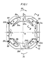
- FIG. 1 shows a terminal board 20 constructed in accordance with this invention and mounted on an axial end of a stator 10.
- Terminal board 20 is a complete annular ring, although it could also be made up of two or more semiannular (meaning partly annular) segments.
- Behind terminal board 20 in FIG. 1 is the stack of metal laminations 12 (see FIG. 2) which forms the main body of the stator.
- Terminal board 20 itself is typically made of an insulating material such as plastic.
- Terminal board 20 typically includes terminal receptacles (e.g., receptacles 22a-d), at least some of which hold or will receive metal terminals (e.g., terminal 50 in FIG.
- the terminal receptacles 22 shown in the drawings are for terminals of the type which are generally inserted when the stator is in the termination station after the coils have been wound.
- the depicted terminals 50, on the other hand, are of a type which are generally inserted before the terminal board is applied to the stator.
- stator 10 has two poles 14a and 14b, although it could have more poles if desired.
- terminal board 20 In front of each pole 14 terminal board 20 has a coil holder 24a, 24b which extends axially outward from the portion of the terminal board which is adjacent to the surface of the pole that is concentric with central longitudinal axis 16.
- each coil holder At the axial end of each coil holder 24 which is remote from the main annular portion of terminal board 20 each coil holder has a coil retainer tab 26a, 26b which projects radially outward from the associated coil holder.
- each insert 30 is preferably axially somewhat longer than the stator stack (excluding terminal boards 20) so that each insert projects slightly from each axial end of the stator stack prior to attachment of terminal boards 20.
- a terminal board 20 is mounted on each axial end of the stator stack as shown in FIGS. 1 and 2.
- the main annular portion of terminal board 20 has generally the same shape and extent as the associated axial end of stator stack 12 except for a lip or bead 40 which projects over and therefore covers the axial end of the adjacent insert 30 (see also FIG. 2).
- FIG. 3a in which the reference numbers 20 and 24 are used merely to help the reader identify generally corresponding parts of the structure and not to mean that the FIG. 2 structure forms part of the present invention.
- lip or bead 40 protects the axial ends of inserts 30 during winding of the coils on poles 14, especially when these coils are wound without winding forms.
- the insert can corrugate the insert (due to the wire sliding or running on the exposed surface of the insert), causing the material of the insert to displace at other locations (e.g., in region C where the insert may bulge radially inwardly so that it can vibrate against the stator stack when the finished motor is operated or so that the insert interferes with rotation of the armature). Hitting of the insert can also break through the insert, with the possible loss of insulation between the coil and the stator stack.
- the portion of lip or bead 40 which is radially outward from region A protects this part of the axial end of insert 30 and thereby eliminates or at least greatly reduces the foregoing possible problems.
- a smooth surface which is typically harder than insert 30
- lip or bead 40 may also improve the resulting coils, for example, by helping the coils to wind more tightly, regularly, and densely about the poles and by reducing the possibility that voids will form in the coil, especially close to the axial end of the stator, as the winding proceeds.
- each pole 14 On the other side of each pole 14, as the wire being wound re-enters the stator (e.g., adjacent region B), the wire must bend generally about edge B and may also need to move along edge B.
- lip or bead 40 overhanging and thereby protecting the axial end of insert 30 prevents the wire from damaging the insert, with possible loss of insulation between the coil and the stator stack.
- Lip or bead 40 in region B also ensures that the wire contacts a smooth, hard surface which facilitates motion of the wire along edge B. As in the case of the portion of the lip or bead 40 in the vicinity of region A, this may help produce better windings by increasing the tightness, regularity, density, and completeness of the coils.
- lip or bead 40 on the terminal boards at both ends of the stator stack helps to hold inserts 30 in their proper axial positions in the stator and reduce the risk that an insert may be dislocated by handling of the stator or before enough windings have been applied to permanently retain the inserts.
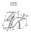
- Small, localized clips 34 (FIG. 3b) have been used in the past to help hold insert 30 in place both axially and radially. But structures like continuous lip or bead 40, with all the additional advantages described above, were unknown prior this invention.
- That portion of terminal board 20 is thicker in the radial direction than either the portion which is immediately adjacent the stator stack or the portion which forms coil holder 24.
- the transition from coil holder 24 to this thicker portion is preferably inclined as shown at 42 in FIGS. 2 and 5. This incline promotes running of wire being wound toward the adjacent stator pole, which tends to improve the coils in the ways that have been mentioned above.
- the bead surface 44 on the other side of the channel depicted in FIG. 2 is preferably inclined relative to both the longitudinal axis of the stator and the axial end face of the stator so that surfaces 42 and 44 are synclinal in the direction into the stator.
- wire grippers 90 can be mounted on one or both axial ends of the stator (e.g., by being mounted on one or both of terminal boards 20 as shown in FIGS. 1 and 6) for temporarily holding a coil lead prior to permanent termination of that lead on the terminal 50 in an adjacent terminal receptacle 22.
- Grippers 90 can be at any convenient locations on ends of the stator or the associated terminal boards 20. After the stator has been wound, it is typically passed from the winding station to a terminating station. In the terminating station, each coil lead is removed from its gripper 90 and permanently terminated on a terminal 50 in a terminal receptacle 22.
- FIGS. 1, 6, and 7 show one illustrative form of gripper 90 which is integral with terminal board 20.
- Gripper 90 has two upstanding members 92 and 94 with a slot 96 therebetween. The smallest portion of slot 96 is narrower than the diameter of the wire lead 72 to be held in gripper 90. Accordingly, wire lead 72 can be pushed down into slot 96 which then holds the lead until it is subsequently lifted out and relocated to a terminal 50 in an adjacent terminal receptacle 22.
- the number of grippers 90 will typically correspond to the number of leads to be temporarily held, although additional grippers 90 may be provided in the event that a lead is to be temporarily anchored in a first gripper, then relocated to one or more other grippers before being finally terminated on a terminal 50. Note that some motors are made with more than one coil per pole, and/or with coils having intermediate taps. Grippers 90 can be used for the start, intermediate (if any), and finish leads of each coil.
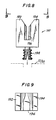
- FIGS. 8 and 9 show an alternative gripper 190 which is not integral with terminal board 20. Instead, gripper 190 is a separate element which can be plugged into a simple hole in terminal 20 (or stator body 12 if the gripper is at a location not covered by terminal board 20) by means of pin 198. As in the case of gripper 90, a wire lead can be temporarily held in slot 196 between upstanding members 192 and 194. At the appropriate time, the wire lead can be removed from slot 196 and permanently secured to a terminal 50. Thereafter, gripper 190 can be removed from the stator (e.g., by pulling pin 198 out of the associated terminal board hole or by shearing gripper 190 off above pin 198).
- FIG. 10 shows stator 10 being transported vertically on pallet 120 having pin 122, central column 124, and peg 126 for positioning the pallet with the required precision.
- coils 70 have been wound on the stator, leads 72 are temporarily secured in grippers 90, and terminals 50 are in place but not yet connected to wire leads 72.
- FIG. 10 shows stator 10 as it might be conveyed on pallet 120 from a coil winding station to a lead terminating station.
- stator 10 can be readily placed on or removed from pallet 120 at either or both of the winding and lead terminating stations.
- the area around the stator is not cluttered by lead-holding elements, thereby simplifying the design of the apparatus required to remove the stator 10 from pallet 120 or to place the stator back on the pallet.
- the amount of lead wire required to reach the wire-holding elements is also reduced by having the elements (i.e., grippers 90) right on the stator.
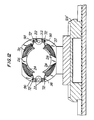
- FIGS. 11 and 12 show that similar advantages obtain when stator 10 is transported horizontally on pallet 120′. Such horizontal transport may be advantageous in certain situations (e.g., when leads are to be terminated at both ends of the stator).
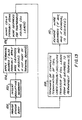
- FIG. 13 is a flow chart of the stator making methods of this invention.
- FIG. 13 is also a block diagram of the stator making apparatus of this invention.
- stator stack or body 12 is provided in any conventional manner.
- insulating members 30 are inserted in the longitudinal channels which are present in the stator between circumferentially adjacent poles.
- This step or station can also be conventional (see, for example, Luciani et al. U.S. patent 4,831,716 which shows suitable apparatus of this kind).
- terminal boards 20 are attached to the axial ends of the stator body in any conventional manner.
- One or both of these terminal boards may include wire grippers 90.
- wire grippers 90 may be mounted directly on stator body 12 in step or station 104.
- step or station 106 coils are wound on the stator poles.
- This or other known apparatus can be readily adapted to deposit the start and/or finish leads of the coils in wire grippers 90 if desired. (Of course, if wire grippers 90 are not needed and the start and finish leads can be anchored directly in terminal receptacles 22, then other known apparatus such as that shown in Pearsall U.S.
- patent 4,074,018 can be used in step or station 106 for handling the start and finish leads.
- Various known coil winding needle structures and motions can be used to actually wind the coils in step or station 106 (see, for example, Wheeler U.S. patent 4,612,702 and Luciani U.S. patent 4,762,283 which show suitable needle structures and motions).
- the stator is typically moved from the winding station to a terminating station 108 where the start and finish leads are terminated or where the termination of those leads is completed.
- a terminating station 108 where the start and finish leads are terminated or where the termination of those leads is completed.
- the start and finish leads have been anchored directly in terminal receptacles 22 as in Pearsall U.S. patent 4,074,418, then in step or station 108 a metal terminal is typically pushed into each terminal receptacle in the known manner to make contact with and complete the termination of each lead.
- the coil leads are being temporarily held by wire grippers 90, then in step or station 108 each such lead is removed from its wire gripper and transferred to the appropriate permanent metal terminal.
- wire grippers 90 may be removed by any suitable technique such as by shearing them off or by pulling them out if they are plugged into the stator.
- wire grippers 90 can be mounted directly on stator stack or body 12 or can be mounted on terminal boards 20 as explained above.
Landscapes
- Engineering & Computer Science (AREA)
- Power Engineering (AREA)
- Manufacturing & Machinery (AREA)
- Insulation, Fastening Of Motor, Generator Windings (AREA)
- Manufacture Of Motors, Generators (AREA)
Abstract
Description
- This invention relates to methods and apparatus for making stators for electric motors and similar machines such as generators. Although the invention is described herein in the context of its application to electric motor stators, it will be understood that it is equally applicable to other types of stators such as have been mentioned.
- Terminal boards for electric motor stators are insulating members which are typically placed on both axial ends of the main stator body for such purposes as supporting the axial ends of the windings wound on the poles of the stator and providing insulated attachment points for the terminals at which the ends of the coil wires can be connected to wires external to the stator.
- Recently there has been increasing interest in winding stators without winding forms (see, for example, Wheeler U.S. patent 4,612,702). This can simplify the winding apparatus and speed the winding process, but it can also increase the strain and wear on the insulating inserts which are typically placed in the stator between circumferentially adjacent poles in order to prevent short circuits between the coils and the stator. Such strain and wear can compromise the insulating effectiveness of the insulating member, possibly resulting in short circuits to the stator. Dislocation or distortion of the insulating member may also occur, possibly resulting in vibration or interference with free rotation of the armature in the finished motor.
- In view of the foregoing, it is an object of this invention to provide stator making methods and apparatus, and especially terminal boards, which better protect the associated insulating inserts, especially during winding without winding forms, but even when winding forms are used, if desired.
- Another problem which may be exacerbated when winding without winding forms is the possibility that some winding turns in the axial ends of the coils, and especially those winding turns which are intended to fill the area close to the axial end of the stator and in the radially outermost portion of the coil, may not be sufficiently tight or close together to preclude undesirable vibration of those winding turns during operation of the finished motor.
- It is therefore another object of this invention to provide stator making methods and apparatus, and especially terminal boards, which promote tight, regular, and complete winding and filling of the stator coils, especially during winding without winding forms, but also when winding forms are used, if desired.
- In some electric motor stators the ends of the coil wires (i.e., the so-called start and finish leads) are anchored directly in the terminal receptacles on the terminal board (see, for example, Pearsall U.S. patent 4,074,418). Metal terminals are then pushed into the receptacles to make electrical contact with the coil wires. In other motors, however, the ends of the coil wires must be held temporarily during and after winding. At a subsequent termination station the ends of the coil wires are relocated to terminals mounted on the terminal board. In the past, the elements for temporarily holding the ends of the coil wires have been provided on the pallets or other structures which support and/or convey the stators (see, for example, Wheeler U.S. patent 4,612,702, Nussbaumer et al. U.S. patent 4,679,312, and Santandrea et al. U.S. patent 4,713,883). Providing elements for temporarily holding the ends of the wire coils on the pallet or other coil supporting structure (hereinafter referred to generically as a pallet) has a number of disadvantages. For one thing, these wire-holding elements complicate the pallet, thereby increasing its cost. The presence of these wire-holding elements around the stator also makes it more difficult to place the stator on or remove the stator from the pallet. The stator-handling elements which perform these tasks must be designed so that they do not interfere with the wire-holding elements. The need for wire-holding elements on the pallet may make it difficult or impossible to use the same pallet for stators of different size (e.g., different stack height). A substantial amount of wire may be needed to temporarily reach wire-holding elements on the pallet. This wire may have to be cut off and discarded when the wire is finally permanently terminated on the terminal board. The fact that the coil ends are temporarily attached to the pallet may make it more difficult or impossible to use certain permanent termination techniques which would otherwise be advantageous. For example, it may be difficult or impossible to employ permanent termination apparatus which requires removal of the stator from the pallet.
- In view of considerations such as the foregoing, it is still another object of this invention to provide improved methods and apparatus for temporarily holding the ends of coil wires during and after winding the coils on the poles of a stator.
- These and other objects of the invention are accomplished in accordance with the principles of the invention by providing a terminal board having a lip or bead which projects out over the axial end of the insulating member which lines the channel between circumferentially adjacent poles of a stator. This lip or bead performs such functions as protecting the end of the insulating member, preventing the insulating member from shifting axially relative to the stator, and ensuring that the wire being wound bears on the terminal board and not on the more fragile axial end of the insulating member as the wire is drawn around the poles of the stator. This lip or bead also promotes depositing the axial ends of the coils close to the axial ends of the stator, thereby improving the tightness, regularity, density, and efficiency of the coils. The foregoing features are especially useful when winding stators without winding forms, although they may also be useful even when winding forms are employed.
- The stators (preferably the terminal boards) of this invention may also have grippers for temporarily holding the ends of the coil wires so that these ends can be subsequently picked up and relocated to terminals permanently mounted on the terminal board. This has a great many advantages including facilitating processing of stators on and off pallets, simplifying the design of the apparatus which must handle the stator after winding but before the coils are permanently terminated, facilitating the design of apparatus which can handle stators of different sizes (e.g., different stack heights), and reducing wire consumption.
- Further features of the invention, its nature and various advantages will be more apparent from the accompanying drawings and the following detailed description of the preferred embodiments.
-
- FIG. 1 is an axial end view of an illustraive embodiment of a stator constructed in accordance with the principles of this invention prior to winding coils on the stator poles.
- FIG. 2 is a partial sectional view taken along the line 2-2 in FIG. 1.
- FIG. 3a is a view similar to FIG. 2 but showing a prior art structure.
- FIG. 3b is a partial perspective view of a prior art stator structure.
- FIG. 4 is a partial sectional view taken along the line 4-4 in FIG. 1.
- FIG. 5 is a partial sectional view taken along the line 5-5 in FIG. 4.
- FIG. 6 is an enlargement of a portion of FIG. 1.
- FIG. 7 is a detail view taken along the line 7-7 in FIG. 6.
- FIG. 8 is an elevational view of an alternative embodiment of apparatus constructed in accordance with this invention.
- FIG. 9 is a view taken along the line 9-9 in FIG. 8.
- FIG. 10 is a partly sectional view of a stator constructed in accordance with this invention mounted on a pellet.
- FIG. 11 is a partly sectional view of a stator constructed in accordance with this invention mounted in an alternative way on an alternative pallet.
- FIG. 12 is a sectional view taken along the line 12-12 in FIG. 11.
- FIG. 13 is a flow chart of stator making methods in accordance with this invention. FIG. 13 is also a schematic block diagram of stator making apparatus in accordance with this invention.
- FIG. 1 shows a
terminal board 20 constructed in accordance with this invention and mounted on an axial end of astator 10.Terminal board 20 is a complete annular ring, although it could also be made up of two or more semiannular (meaning partly annular) segments. Behindterminal board 20 in FIG. 1 is the stack of metal laminations 12 (see FIG. 2) which forms the main body of the stator.Terminal board 20 itself is typically made of an insulating material such as plastic.Terminal board 20 typically includes terminal receptacles (e.g.,receptacles 22a-d), at least some of which hold or will receive metal terminals (e.g.,terminal 50 in FIG. 2) to which the ends of the stator coil wires are attached to facilitate making electrical connections to the stator. (Theterminal receptacles 22 shown in the drawings are for terminals of the type which are generally inserted when the stator is in the termination station after the coils have been wound. The depictedterminals 50, on the other hand, are of a type which are generally inserted before the terminal board is applied to the stator. These two different types of apparatus are depicted merely to make it clear that the present invention can be used in either case.) - In the depicted illustrative embodiment,
stator 10 has twopoles terminal board 20 has acoil holder 24a, 24b which extends axially outward from the portion of the terminal board which is adjacent to the surface of the pole that is concentric with centrallongitudinal axis 16. At the axial end of eachcoil holder 24 which is remote from the main annular portion ofterminal board 20 each coil holder has acoil retainer tab 26a, 26b which projects radially outward from the associated coil holder. - Before
terminal board 20 is mounted onstator stack 12, an insulating member, insert, orliner insert 30 is preferably axially somewhat longer than the stator stack (excluding terminal boards 20) so that each insert projects slightly from each axial end of the stator stack prior to attachment ofterminal boards 20. Afterinserts 30 are in place, aterminal board 20 is mounted on each axial end of the stator stack as shown in FIGS. 1 and 2. - As can be seen in FIG. 1, the main annular portion of
terminal board 20 has generally the same shape and extent as the associated axial end ofstator stack 12 except for a lip orbead 40 which projects over and therefore covers the axial end of the adjacent insert 30 (see also FIG. 2). The prior situation without this bead is illustrated by FIG. 3a (in which thereference numbers bead 40 protects the axial ends ofinserts 30 during winding of the coils on poles 14, especially when these coils are wound without winding forms. In particular, it has been found that when the stator is wound without terminal boards having lip or bead 40 (e.g., terminal boards as shown in FIG. 3a), the wire emerging, for example, from region A tends to hit the axial end portion of theadjacent insert 30 which is radially outward from region A. (Arrows 32 show the direction of motion of the needles which wind the wire in this example.) This hitting ofinsert 30 can have several undesirable results. For example, it can corrugate the insert (due to the wire sliding or running on the exposed surface of the insert), causing the material of the insert to displace at other locations (e.g., in region C where the insert may bulge radially inwardly so that it can vibrate against the stator stack when the finished motor is operated or so that the insert interferes with rotation of the armature). Hitting of the insert can also break through the insert, with the possible loss of insulation between the coil and the stator stack. The portion of lip orbead 40 which is radially outward from region A protects this part of the axial end ofinsert 30 and thereby eliminates or at least greatly reduces the foregoing possible problems. - This portion of lip or
bead 40, as well as other portions of the lip or bead in the vicinity of region A, also provides a smooth surface (which is typically harder than insert 30) on which the wire can more readily move or run in the circumferential direction as the end of the wire-winding needle (not shown) passes over the top (or bottom) ofretainer tab 26 in order to pull the windings tightly around the poles. By facilitating the circumferential movement of coil wires during winding in this manner, lip orbead 40 may also improve the resulting coils, for example, by helping the coils to wind more tightly, regularly, and densely about the poles and by reducing the possibility that voids will form in the coil, especially close to the axial end of the stator, as the winding proceeds. - On the other side of each pole 14, as the wire being wound re-enters the stator (e.g., adjacent region B), the wire must bend generally about edge B and may also need to move along edge B. Once again, the presence of lip or
bead 40 overhanging and thereby protecting the axial end ofinsert 30 prevents the wire from damaging the insert, with possible loss of insulation between the coil and the stator stack. Lip orbead 40 in region B also ensures that the wire contacts a smooth, hard surface which facilitates motion of the wire along edge B. As in the case of the portion of the lip orbead 40 in the vicinity of region A, this may help produce better windings by increasing the tightness, regularity, density, and completeness of the coils. - Another advantage of lip or
bead 40 on the terminal boards at both ends of the stator stack is that these lips or beads help to holdinserts 30 in their proper axial positions in the stator and reduce the risk that an insert may be dislocated by handling of the stator or before enough windings have been applied to permanently retain the inserts. Small, localized clips 34 (FIG. 3b) have been used in the past to help holdinsert 30 in place both axially and radially. But structures like continuous lip orbead 40, with all the additional advantages described above, were unknown prior this invention. - Note that (as shown in FIG. 2) in order to prevent
coil holders 24 from becoming too thick as a result of the need to provide the adjacent portion of lip orbead 40, that portion ofterminal board 20 is thicker in the radial direction than either the portion which is immediately adjacent the stator stack or the portion which formscoil holder 24. The transition fromcoil holder 24 to this thicker portion is preferably inclined as shown at 42 in FIGS. 2 and 5. This incline promotes running of wire being wound toward the adjacent stator pole, which tends to improve the coils in the ways that have been mentioned above. Also note that thebead surface 44 on the other side of the channel depicted in FIG. 2 is preferably inclined relative to both the longitudinal axis of the stator and the axial end face of the stator so thatsurfaces - If desired,
wire grippers 90 can be mounted on one or both axial ends of the stator (e.g., by being mounted on one or both ofterminal boards 20 as shown in FIGS. 1 and 6) for temporarily holding a coil lead prior to permanent termination of that lead on the terminal 50 in an adjacentterminal receptacle 22.Grippers 90 can be at any convenient locations on ends of the stator or the associatedterminal boards 20. After the stator has been wound, it is typically passed from the winding station to a terminating station. In the terminating station, each coil lead is removed from itsgripper 90 and permanently terminated on a terminal 50 in aterminal receptacle 22. - Although various gripper constructions can be used, FIGS. 1, 6, and 7 show one illustrative form of
gripper 90 which is integral withterminal board 20.Gripper 90 has twoupstanding members slot 96 therebetween. The smallest portion ofslot 96 is narrower than the diameter of thewire lead 72 to be held ingripper 90. Accordingly,wire lead 72 can be pushed down intoslot 96 which then holds the lead until it is subsequently lifted out and relocated to a terminal 50 in an adjacentterminal receptacle 22. - The number of
grippers 90 will typically correspond to the number of leads to be temporarily held, althoughadditional grippers 90 may be provided in the event that a lead is to be temporarily anchored in a first gripper, then relocated to one or more other grippers before being finally terminated on a terminal 50. Note that some motors are made with more than one coil per pole, and/or with coils having intermediate taps.Grippers 90 can be used for the start, intermediate (if any), and finish leads of each coil. - If desired, after they have performed their temporary wire-holding function, grippers 90 can be knocked off or otherwise removed from the stator. For example, FIGS. 8 and 9 show an
alternative gripper 190 which is not integral withterminal board 20. Instead,gripper 190 is a separate element which can be plugged into a simple hole in terminal 20 (orstator body 12 if the gripper is at a location not covered by terminal board 20) by means ofpin 198. As in the case ofgripper 90, a wire lead can be temporarily held inslot 196 betweenupstanding members slot 196 and permanently secured to a terminal 50. Thereafter,gripper 190 can be removed from the stator (e.g., by pullingpin 198 out of the associated terminal board hole or by shearinggripper 190 off above pin 198). - The placement of
grippers 90 or 190 (hereinafter referred to generically as grippers 90) onstator stack 12 orterminal board 20 rather than on the pallet or other apparatus which holds the stator during processing has several important advantages. For example, FIG. 10 shows stator 10 being transported vertically onpallet 120 havingpin 122,central column 124, and peg 126 for positioning the pallet with the required precision. In FIG. 10coils 70 have been wound on the stator, leads 72 are temporarily secured ingrippers 90, andterminals 50 are in place but not yet connected to wire leads 72. Accordingly, FIG. 10 shows stator 10 as it might be conveyed onpallet 120 from a coil winding station to a lead terminating station. - Because leads 72 are held in
grippers 90 on the stator rather than in elements mounted onpallet 120,stator 10 can be readily placed on or removed frompallet 120 at either or both of the winding and lead terminating stations. The area around the stator is not cluttered by lead-holding elements, thereby simplifying the design of the apparatus required to remove thestator 10 frompallet 120 or to place the stator back on the pallet. The amount of lead wire required to reach the wire-holding elements is also reduced by having the elements (i.e., grippers 90) right on the stator. And if it is desired to process stators (e.g.,stators 10′) of a different size (e.g., a different stack height), no changes or considerably fewer charges are required to pallet 120 than if wire leads 72 were held by elements on the pallet. FIGS. 11 and 12 show that similar advantages obtain whenstator 10 is transported horizontally onpallet 120′. Such horizontal transport may be advantageous in certain situations (e.g., when leads are to be terminated at both ends of the stator). - As has been mentioned, FIG. 13 is a flow chart of the stator making methods of this invention. FIG. 13 is also a block diagram of the stator making apparatus of this invention. In step or
station 100 stator stack orbody 12 is provided in any conventional manner. In step orstation 102 insulatingmembers 30 are inserted in the longitudinal channels which are present in the stator between circumferentially adjacent poles. This step or station can also be conventional (see, for example, Luciani et al. U.S. patent 4,831,716 which shows suitable apparatus of this kind). In step orstation 104terminal boards 20 are attached to the axial ends of the stator body in any conventional manner. One or both of these terminal boards may includewire grippers 90. Alternatively,wire grippers 90 may be mounted directly onstator body 12 in step orstation 104. - In step or
station 106 coils are wound on the stator poles. Luciani et al. U.S. patent application Serial No. 321,919, filed March 13, 1989, shows apparatus suitable for manipulating the start and finish leads of stator coils. This or other known apparatus can be readily adapted to deposit the start and/or finish leads of the coils inwire grippers 90 if desired. (Of course, if wire grippers 90 are not needed and the start and finish leads can be anchored directly interminal receptacles 22, then other known apparatus such as that shown in Pearsall U.S. patent 4,074,018 can be used in step orstation 106 for handling the start and finish leads.) Various known coil winding needle structures and motions can be used to actually wind the coils in step or station 106 (see, for example, Wheeler U.S. patent 4,612,702 and Luciani U.S. patent 4,762,283 which show suitable needle structures and motions). - Following step or
station 106, the stator is typically moved from the winding station to a terminatingstation 108 where the start and finish leads are terminated or where the termination of those leads is completed. For example, if the start and finish leads have been anchored directly interminal receptacles 22 as in Pearsall U.S. patent 4,074,418, then in step or station 108 a metal terminal is typically pushed into each terminal receptacle in the known manner to make contact with and complete the termination of each lead. On the other hand, if the coil leads are being temporarily held bywire grippers 90, then in step orstation 108 each such lead is removed from its wire gripper and transferred to the appropriate permanent metal terminal. The known apparatus for transferring such leads from the wire grippers on pallets or other stator holding apparatus to permanent terminals as in Wheeler U.S. patent 4,612,702, Nussbaumer et al. U.S. patent 4,679,312, and Santandrea et al. U.S. patent 4,713,883 can be readily modified to transfer leads fromwire grippers 90 topermanent terminals 50. Note that the principle disclosed in Santandrea et al. U.S. patent 4,713,883 of winding and terminating the stator on the pallet can be used with this invention if desired. - If wire grippers 90 have been used, and if it is desired that they not remain on the finished stator, then in step or
station 110wire grippers 90 may be removed by any suitable technique such as by shearing them off or by pulling them out if they are plugged into the stator. - It will be understood that the foregoing is merely illustrative of the principles of this invention and that various modifications can be made by those skilled in the art without departing from the scope and spirit of the invention. For example,
wire grippers 90 can be mounted directly on stator stack orbody 12 or can be mounted onterminal boards 20 as explained above.
Claims (12)
first and second members separated from one another by a slot for receiving said at least one of said leads, the spacing between said first and second members being less than the diameter of said at least one of said leads so that said at least one of said leads is releasably retained in said slot.
providing a hollow annular stator body having a plurality of radially inwardly projecting poles, circumferentially adjacent poles defining a longitudinal channel therebetween;
lining the surface of said channel with an insulating member;
mounting a terminal board on each axial end of said stator body so that a portion of said terminal board overhangs the adjacent axial end of said insulator member; and
winding a coil of wire around each pole.
providing a hollow annular stator body having at least one radially inwardly projecting pole;
mounting a terminal board having at least one terminal receptacle on at least one end of said stator body;
mounting a wire gripper on said at least one end of said stator body;
winding a coil of wire having start and finish leads around said pole;
temporarily securing at least one of said leads in said wire gripper;
moving said stator to a terminating station; and
at said terminating station, transferring said at least one lead from said wire gripper to a terminal mounted in said terminal receptacle and attaching said at least one lead to said terminal.
removing said wire gripper from said stator body after performance of said transferring step.
means for providing a hollow annular stator body having a plurality of radially inwardly projecting poles, circumferentially adjacent poles defining a longitudinal channel therebetween;
means for lining the surface of said channel with an insulating member;
means for mounting a terminal board on each axial end of said stator body so that a portion of said terminal board overhangs the adjacent axial end of said insulating member; and
winding a coil of wire around each pole.
means for providing a hollow annular stator body having at least one radially inwardly projecting pole;
means for mounting a terminal board having at least one terminal receptacle on at least one end of said stator body;
means for mounting a wire gripper on said at least one end of said stator body;
means for winding a coil of wire having leads around said pole;
means for temporarily securing at least one of said leads in said wire gripper; and
means for transferring said at least one lead from said wire gripper to a terminal mounted in said terminal receptacle and attaching said at least one lead to said terminal.
means for removing said wire gripper from said stator body after said at least one lead has been transferred from said wire gripper to said terminal.
Priority Applications (1)
| Application Number | Priority Date | Filing Date | Title |
|---|---|---|---|
| EP94102700A EP0612139B2 (en) | 1989-07-26 | 1990-06-06 | Methods and apparatus for making stators for electric motors and the like, and improved terminal boards therefor |
Applications Claiming Priority (2)
| Application Number | Priority Date | Filing Date | Title |
|---|---|---|---|
| US07/385,570 US4994697A (en) | 1989-07-26 | 1989-07-26 | Stator terminal board |
| US385570 | 1989-07-26 |
Related Child Applications (2)
| Application Number | Title | Priority Date | Filing Date |
|---|---|---|---|
| EP94102700A Division EP0612139B2 (en) | 1989-07-26 | 1990-06-06 | Methods and apparatus for making stators for electric motors and the like, and improved terminal boards therefor |
| EP94102700.5 Division-Into | 1994-02-23 |
Publications (3)
| Publication Number | Publication Date |
|---|---|
| EP0411275A2 true EP0411275A2 (en) | 1991-02-06 |
| EP0411275A3 EP0411275A3 (en) | 1991-03-06 |
| EP0411275B1 EP0411275B1 (en) | 1994-09-14 |
Family
ID=23521969
Family Applications (2)
| Application Number | Title | Priority Date | Filing Date |
|---|---|---|---|
| EP94102700A Expired - Lifetime EP0612139B2 (en) | 1989-07-26 | 1990-06-06 | Methods and apparatus for making stators for electric motors and the like, and improved terminal boards therefor |
| EP90110654A Expired - Lifetime EP0411275B1 (en) | 1989-07-26 | 1990-06-06 | Methods and apparatus for making stators for electric motors and the like, and improved terminal boards therefor |
Family Applications Before (1)
| Application Number | Title | Priority Date | Filing Date |
|---|---|---|---|
| EP94102700A Expired - Lifetime EP0612139B2 (en) | 1989-07-26 | 1990-06-06 | Methods and apparatus for making stators for electric motors and the like, and improved terminal boards therefor |
Country Status (5)
| Country | Link |
|---|---|
| US (1) | US4994697A (en) |
| EP (2) | EP0612139B2 (en) |
| JP (1) | JPH03222644A (en) |
| AT (2) | ATE111655T1 (en) |
| DE (2) | DE69029523T3 (en) |
Cited By (5)
| Publication number | Priority date | Publication date | Assignee | Title |
|---|---|---|---|---|
| FR2726699A1 (en) * | 1994-11-04 | 1996-05-10 | Valeo Equip Electr Moteur | Inductive field magnet for rotating electric machine such as starter for motor vehicle IC engine |
| EP0732001A4 (en) * | 1993-12-03 | 1998-03-18 | Globe Products Inc | STATOR CONDUCTING WIRE CONNECTION METHOD AND APPARATUS |
| EP0993095A1 (en) * | 1998-10-06 | 2000-04-12 | ebm Werke GmbH & Co. | Stator for electric motor |
| ES2158760A1 (en) * | 1998-11-17 | 2001-09-01 | Escola Del Treball Del Ripolle | Retention element for fixing the free end of the thread of a winder and procedure and device for its positioning |
| EP2605384A3 (en) * | 2011-12-14 | 2017-12-13 | Metabowerke GmbH | Method for winding the field coils of a stator and this stator |
Families Citing this family (14)
| Publication number | Priority date | Publication date | Assignee | Title |
|---|---|---|---|---|
| EP0468307A3 (en) * | 1990-07-27 | 1993-08-11 | Axis S.P.A. | Methods and apparatus for processing stators |
| US5765274A (en) * | 1996-05-21 | 1998-06-16 | Globe Products Inc. | Stator manufacturing method |
| US7205696B2 (en) * | 2003-09-05 | 2007-04-17 | Black & Decker Inc. | Field assemblies having pole pieces with ends that decrease in width, and methods of making same |
| US7211920B2 (en) * | 2003-09-05 | 2007-05-01 | Black & Decker Inc. | Field assemblies having pole pieces with axial lengths less than an axial length of a back iron portion and methods of making same |
| US20060226729A1 (en) * | 2003-09-05 | 2006-10-12 | Du Hung T | Field assemblies and methods of making same with field coils having multiple coils |
| US20050189844A1 (en) * | 2003-09-05 | 2005-09-01 | Du Hung T. | Field assemblies having pole pieces with dovetail features for attaching to a back iron piece(s) and methods of making same |
| WO2005027306A2 (en) * | 2003-09-05 | 2005-03-24 | Black & Decker Inc. | Field assemblies and methods of making same |
| US7078843B2 (en) * | 2003-09-05 | 2006-07-18 | Black & Decker Inc. | Field assemblies and methods of making same |
| EP2568573A3 (en) * | 2005-03-07 | 2014-06-04 | Black & Decker Inc. | Power Tools with Motor Having a Multi-Piece Stator |
| US8339235B2 (en) | 2008-08-06 | 2012-12-25 | Beckert James J | Housing securing apparatus for electrical components, especially fuses |
| JP5232573B2 (en) * | 2008-08-28 | 2013-07-10 | 株式会社ミツバ | motor |
| JP5682430B2 (en) * | 2011-04-15 | 2015-03-11 | 三菱電機株式会社 | Electric blower |
| CN106374699A (en) * | 2016-09-22 | 2017-02-01 | 无锡江南奕帆电力传动科技股份有限公司 | Device for automatic winding of stator coil |
| DE102017105089A1 (en) * | 2017-03-10 | 2018-09-13 | Kolektor Group D.O.O. | electric motor |
Family Cites Families (23)
| Publication number | Priority date | Publication date | Assignee | Title |
|---|---|---|---|---|
| DE1613352B2 (en) † | 1967-01-26 | 1973-02-08 | Karl M Reich Maschinenfabrik, 7440 Nurtingen | INSULATION BODY FOR INSULATING THE FIELD POLE OF AN ELECTRIC MOTOR |
| US3747187A (en) * | 1971-12-20 | 1973-07-24 | Globe Tool Eng Co | Wire handling method and apparatus with multiple function cam actuator |
| FR2168858B2 (en) * | 1972-01-24 | 1977-01-14 | Reich Maschf Gmbh Karl | |
| USRE28831E (en) * | 1973-01-11 | 1976-05-25 | Consolidated Foods Corporation | Electric motor winding |
| US3984712A (en) * | 1974-11-11 | 1976-10-05 | Industra Products, Inc. | End turn shield and winding connector |
| US3979615A (en) * | 1975-02-05 | 1976-09-07 | Amp Incorporated | Field assembly for electric motors |
| US4038573A (en) * | 1975-04-21 | 1977-07-26 | General Signal Corporation | Coil terminating means |
| US3984908A (en) * | 1975-10-01 | 1976-10-12 | Amp Incorporated | Stator terminal assembly machine |
| US4074418A (en) * | 1976-07-23 | 1978-02-21 | The Globe Tool And Engineering Company | Stator coil winding and lead wire connection |
| US4318022A (en) * | 1977-10-25 | 1982-03-02 | General Electric Company | End turn and terminal support for a stator assembly |
| US4224543A (en) * | 1978-08-01 | 1980-09-23 | Rapidsyn Co. | Printed circuit terminal for interconnecting stator coils |
| JPS5734744A (en) * | 1980-08-08 | 1982-02-25 | Toshiba Corp | Insulated core for rotary electric machine |
| JPS5872347A (en) * | 1981-10-26 | 1983-04-30 | Toshiba Corp | Insulation for slot and method thereof |
| AU572468B2 (en) * | 1982-08-23 | 1988-05-12 | F F Seeley Nominees Pty Ltd | Connection guide for electric motor |
| US4585964A (en) * | 1982-09-29 | 1986-04-29 | Emerson Electric Co. | Apparatus and system for terminating the winding wires of a dynamoelectric machine |
| EP0191195B1 (en) * | 1985-02-15 | 1989-08-02 | Micafil Ag | Device for the automatic manufacture of stators for electric motors |
| IT1200443B (en) * | 1985-04-02 | 1989-01-18 | Axis Spa | Electric motor stator winding forming machine |
| US4612702A (en) * | 1985-05-22 | 1986-09-23 | Black & Decker Inc. | Field coil winding |
| GB2177549A (en) * | 1985-07-01 | 1987-01-21 | Easthorpe Investments Ltd | Supporting spool for electrical windings |
| IT1185206B (en) * | 1985-07-09 | 1987-11-04 | Axis Spa | MACHINE AND PROCEDURE FOR THE FORMATION OF WINDINGS ON THE STATORS OF ELECTRIC MOTORS |
| EP0209162B1 (en) * | 1985-07-11 | 1991-08-21 | AXIS S.p.A. | Production line for pallet mounted electric motor stators |
| US4885496A (en) * | 1987-07-24 | 1989-12-05 | Black & Decker Inc. | Stator end member and assemblies therewith and methods of assembly |
| US4831716A (en) * | 1988-06-27 | 1989-05-23 | Axis Usa, Inc. | Inserting insulating material into electric motor stators |
-
1989
- 1989-07-26 US US07/385,570 patent/US4994697A/en not_active Expired - Lifetime
-
1990
- 1990-06-06 DE DE69029523T patent/DE69029523T3/en not_active Expired - Fee Related
- 1990-06-06 AT AT90110654T patent/ATE111655T1/en not_active IP Right Cessation
- 1990-06-06 EP EP94102700A patent/EP0612139B2/en not_active Expired - Lifetime
- 1990-06-06 EP EP90110654A patent/EP0411275B1/en not_active Expired - Lifetime
- 1990-06-06 AT AT94102700T patent/ATE146915T1/en not_active IP Right Cessation
- 1990-06-06 DE DE69012476T patent/DE69012476T2/en not_active Expired - Fee Related
- 1990-07-26 JP JP2198979A patent/JPH03222644A/en active Pending
Cited By (5)
| Publication number | Priority date | Publication date | Assignee | Title |
|---|---|---|---|---|
| EP0732001A4 (en) * | 1993-12-03 | 1998-03-18 | Globe Products Inc | STATOR CONDUCTING WIRE CONNECTION METHOD AND APPARATUS |
| FR2726699A1 (en) * | 1994-11-04 | 1996-05-10 | Valeo Equip Electr Moteur | Inductive field magnet for rotating electric machine such as starter for motor vehicle IC engine |
| EP0993095A1 (en) * | 1998-10-06 | 2000-04-12 | ebm Werke GmbH & Co. | Stator for electric motor |
| ES2158760A1 (en) * | 1998-11-17 | 2001-09-01 | Escola Del Treball Del Ripolle | Retention element for fixing the free end of the thread of a winder and procedure and device for its positioning |
| EP2605384A3 (en) * | 2011-12-14 | 2017-12-13 | Metabowerke GmbH | Method for winding the field coils of a stator and this stator |
Also Published As
| Publication number | Publication date |
|---|---|
| US4994697A (en) | 1991-02-19 |
| JPH03222644A (en) | 1991-10-01 |
| DE69029523T2 (en) | 1997-07-10 |
| EP0612139B2 (en) | 2004-03-24 |
| DE69012476T2 (en) | 1995-02-02 |
| EP0612139B1 (en) | 1996-12-27 |
| DE69029523T3 (en) | 2005-02-03 |
| EP0411275A3 (en) | 1991-03-06 |
| ATE111655T1 (en) | 1994-09-15 |
| DE69029523D1 (en) | 1997-02-06 |
| EP0612139A2 (en) | 1994-08-24 |
| EP0411275B1 (en) | 1994-09-14 |
| ATE146915T1 (en) | 1997-01-15 |
| DE69012476D1 (en) | 1994-10-20 |
| EP0612139A3 (en) | 1994-09-14 |
Similar Documents
| Publication | Publication Date | Title |
|---|---|---|
| EP0411275A2 (en) | Methods and apparatus for making stators for electric motors and the like, and improved terminal boards therefor | |
| US5239743A (en) | Method for making stators for electric motors and the like | |
| US5099568A (en) | Methods for making stators for electric motors | |
| JP2523933B2 (en) | Manufacturing method of stator | |
| US6317962B1 (en) | Method for producing a stator of an alternating-current dynamo-electric machine | |
| EP0209091A2 (en) | A method of manufacturing an armature of an a.c. generator for a car | |
| JPH10201150A (en) | Landel core type rotary electric machine | |
| GB1599979A (en) | Stator assemblies | |
| CN100477453C (en) | Wire winder and wire winding method | |
| CN100555802C (en) | The manufacture method of stator and insulating bobbin and this stator | |
| US7227291B2 (en) | Stator for an electrical machine | |
| JP4631243B2 (en) | Electric motor manufacturing method, electric motor | |
| US5291649A (en) | Methods and apparatus for processing stators | |
| JP2007089310A (en) | Coil insertion method and apparatus | |
| US6282775B1 (en) | Methods for injecting stator winding coil groups into a stator core | |
| EP0823770A1 (en) | Wire winding guide for dynamo electric machine | |
| JP2000245120A (en) | Coil assembly for rotating electric machine and method of manufacturing the same | |
| US6923399B1 (en) | Manufacturing methods and apparatus for terminating dynamo-machine component wire coil leads | |
| JPH1198743A (en) | Armature winding and its core groove insertion method | |
| JP2000050581A (en) | Stator manufacturing equipment and stator | |
| JP2002142416A (en) | Method for manufacturing stator of electric motor and hermetic compressor | |
| US7267296B2 (en) | Method and apparatus for winding multi-pole stators with termination hooks | |
| US6230388B1 (en) | Method for producing a stator for electric machines | |
| JP3140656B2 (en) | Winding method | |
| JPH11289721A (en) | Laminated stator core and manufacturing method thereof |
Legal Events
| Date | Code | Title | Description |
|---|---|---|---|
| PUAI | Public reference made under article 153(3) epc to a published international application that has entered the european phase |
Free format text: ORIGINAL CODE: 0009012 |
|
| PUAL | Search report despatched |
Free format text: ORIGINAL CODE: 0009013 |
|
| AK | Designated contracting states |
Kind code of ref document: A2 Designated state(s): AT BE CH DE ES FR GB IT LI NL SE |
|
| RHK1 | Main classification (correction) |
Ipc: H02K 3/52 |
|
| AK | Designated contracting states |
Kind code of ref document: A3 Designated state(s): AT BE CH DE ES FR GB IT LI NL SE |
|
| 17P | Request for examination filed |
Effective date: 19910515 |
|
| 17Q | First examination report despatched |
Effective date: 19921216 |
|
| GRAA | (expected) grant |
Free format text: ORIGINAL CODE: 0009210 |
|
| AK | Designated contracting states |
Kind code of ref document: B1 Designated state(s): AT BE CH DE ES FR GB IT LI NL SE |
|
| PG25 | Lapsed in a contracting state [announced via postgrant information from national office to epo] |
Ref country code: FR Effective date: 19940914 Ref country code: ES Free format text: THE PATENT HAS BEEN ANNULLED BY A DECISION OF A NATIONAL AUTHORITY Effective date: 19940914 Ref country code: NL Effective date: 19940914 Ref country code: AT Effective date: 19940914 Ref country code: BE Effective date: 19940914 |
|
| REF | Corresponds to: |
Ref document number: 111655 Country of ref document: AT Date of ref document: 19940915 Kind code of ref document: T |
|
| REF | Corresponds to: |
Ref document number: 69012476 Country of ref document: DE Date of ref document: 19941020 |
|
| ITF | It: translation for a ep patent filed | ||
| PG25 | Lapsed in a contracting state [announced via postgrant information from national office to epo] |
Ref country code: SE Effective date: 19941214 |
|
| EN | Fr: translation not filed | ||
| NLV1 | Nl: lapsed or annulled due to failure to fulfill the requirements of art. 29p and 29m of the patents act | ||
| PLBE | No opposition filed within time limit |
Free format text: ORIGINAL CODE: 0009261 |
|
| STAA | Information on the status of an ep patent application or granted ep patent |
Free format text: STATUS: NO OPPOSITION FILED WITHIN TIME LIMIT |
|
| 26N | No opposition filed | ||
| REG | Reference to a national code |
Ref country code: GB Ref legal event code: IF02 |
|
| PGFP | Annual fee paid to national office [announced via postgrant information from national office to epo] |
Ref country code: GB Payment date: 20050525 Year of fee payment: 16 |
|
| PG25 | Lapsed in a contracting state [announced via postgrant information from national office to epo] |
Ref country code: GB Free format text: LAPSE BECAUSE OF NON-PAYMENT OF DUE FEES Effective date: 20060606 |
|
| PGFP | Annual fee paid to national office [announced via postgrant information from national office to epo] |
Ref country code: IT Payment date: 20060630 Year of fee payment: 17 |
|
| GBPC | Gb: european patent ceased through non-payment of renewal fee |
Effective date: 20060606 |
|
| PGFP | Annual fee paid to national office [announced via postgrant information from national office to epo] |
Ref country code: CH Payment date: 20080624 Year of fee payment: 19 |
|
| PGFP | Annual fee paid to national office [announced via postgrant information from national office to epo] |
Ref country code: DE Payment date: 20080827 Year of fee payment: 19 |
|
| PG25 | Lapsed in a contracting state [announced via postgrant information from national office to epo] |
Ref country code: IT Free format text: LAPSE BECAUSE OF NON-PAYMENT OF DUE FEES Effective date: 20070606 |
|
| REG | Reference to a national code |
Ref country code: CH Ref legal event code: PL |
|
| PG25 | Lapsed in a contracting state [announced via postgrant information from national office to epo] |
Ref country code: CH Free format text: LAPSE BECAUSE OF NON-PAYMENT OF DUE FEES Effective date: 20090630 Ref country code: LI Free format text: LAPSE BECAUSE OF NON-PAYMENT OF DUE FEES Effective date: 20090630 |
|
| PG25 | Lapsed in a contracting state [announced via postgrant information from national office to epo] |
Ref country code: DE Free format text: LAPSE BECAUSE OF NON-PAYMENT OF DUE FEES Effective date: 20100101 |