EP0411397A1 - Elektromagnetisches Schaltgerät - Google Patents
Elektromagnetisches Schaltgerät Download PDFInfo
- Publication number
- EP0411397A1 EP0411397A1 EP90113796A EP90113796A EP0411397A1 EP 0411397 A1 EP0411397 A1 EP 0411397A1 EP 90113796 A EP90113796 A EP 90113796A EP 90113796 A EP90113796 A EP 90113796A EP 0411397 A1 EP0411397 A1 EP 0411397A1
- Authority
- EP
- European Patent Office
- Prior art keywords
- coil
- switching device
- printed circuit
- contact
- coil connection
- Prior art date
- Legal status (The legal status is an assumption and is not a legal conclusion. Google has not performed a legal analysis and makes no representation as to the accuracy of the status listed.)
- Granted
Links
- 230000001629 suppression Effects 0.000 claims abstract description 3
- 239000004020 conductor Substances 0.000 description 1
- 230000013011 mating Effects 0.000 description 1
- 238000004804 winding Methods 0.000 description 1
Images

Classifications
-
- H—ELECTRICITY
- H01—ELECTRIC ELEMENTS
- H01H—ELECTRIC SWITCHES; RELAYS; SELECTORS; EMERGENCY PROTECTIVE DEVICES
- H01H50/00—Details of electromagnetic relays
- H01H50/02—Bases; Casings; Covers
- H01H50/021—Bases; Casings; Covers structurally combining a relay and an electronic component, e.g. varistor, RC circuit
Definitions
- the invention relates to an electromagnetic switching device, in particular a small contactor, with a lower part receiving the magnet system with the coil and an upper part carrying the contact system and the coil connection, which can be connected mechanically and electrically with respect to the coil connection to the lower part.
- the invention has for its object to provide in a switching device of the type mentioned above the possibility to easily accommodate additional components. This is achieved in a simple manner in a switching device of the type mentioned above in that the upper and lower part is interposed with a printed circuit receiving components, such as interference suppression or overvoltage protection diodes and / or rectifiers, which is connected to the coil connection in the lower part and contacting surfaces for resilient, has contact parts connected to the coil connections in the upper part.
- a printed circuit receiving components such as interference suppression or overvoltage protection diodes and / or rectifiers, which is connected to the coil connection in the lower part and contacting surfaces for resilient, has contact parts connected to the coil connections in the upper part.
- the components are arranged on the side of the printed circuit facing the coil. Here is the anyway between rectangular housing and circle cylindrical coil existing edge space exploited. It is advantageous if the printed circuit is inserted into recesses in the coil body flanges.
- the recess on the coil former flange serves to fix the circuit board on the coil former in order to maintain a defined position of the contact point.
- the resilient contact parts consist of spiral springs which are pushed onto pins attached to the upper part.
- the pins are advantageously parts of knife contact parts of the upper part.
- the knife contacts are cracked using a tool.
- the printed circuit is connected via flexible lines which are soldered to Lyra plug-in connections.
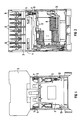
- the small contactor shown in the drawing consists of the lower part 2 receiving the magnet system 1 and the upper part 3 receiving the contact system, which can be connected to the lower part 2 via the latching connection 4.
- the contact system consists of the contact bridges, not shown, which are held in the contact bridge carrier 5 spring-loaded.
- the contact bridge support 5 is in the direction of the dividing line between the lower part 2 and the upper part 3 parallel gela device.
- the contact bridges work together with the bent fixed contact parts (not shown in any more detail) which can be connected in an electrically conductive manner via connecting screws 6 to line ends of the supply line.
- the pair of connecting screws 6 on the right in FIG. 2 is connected to the pin-shaped feed line 7 for the coil 8 of the magnet system 1.
- Coil springs 9 are pushed over the pin-shaped lead 7 and are brought into electrically conductive connection with contact surfaces 10 of a printed circuit board 11 after the lower part 2 and upper part 3 have been joined together.
- diodes 12, specifically facing the coil 8 are fastened to the printed circuit board and connected to the conductor tracks of the printed circuit board.
- Flexible lines 13 serve to connect the lyre contact parts 14 to the printed circuit board 11, ie to the diodes 12 and the ends of the coil 8.
- the ends of the coil 8 are wound around winding pins 15 of the lyre contact parts 14. At this point, the ends of the flexible lines 13 are also soldered. If no wiring of the coil is desired, the printed circuit board can be omitted.
- the knife contact parts of the pin-shaped lead 7 are inserted when joining together the lower and upper part, so that the outer row of screws 6 is only used for connecting the coil itself.
- the pin-shaped feed line can be produced by breaking off parts of the usual knife-shaped contact parts if necessary.
- the coil springs 9 are then pushed onto the pin-shaped feed line.
- the printed circuit board rests on edges 16 of the coil flanges 17, so that the pressure on the contact surfaces 10 from the coil springs 9 cannot cause any damage.
Landscapes
- Physics & Mathematics (AREA)
- Electromagnetism (AREA)
- Keying Circuit Devices (AREA)
- Relay Circuits (AREA)
- Switch Cases, Indication, And Locking (AREA)
- Coupling Device And Connection With Printed Circuit (AREA)
- Electronic Switches (AREA)
- Burglar Alarm Systems (AREA)
- Vehicle Body Suspensions (AREA)
- Shielding Devices Or Components To Electric Or Magnetic Fields (AREA)
Abstract
Description
- Die Erfindung bezieht sich auf ein elektromagnetisches Schaltgerät, insbesondere Kleinschütz, mit einem das Magnetsystem mit der Spule aufnehmenden Unterteil und einem das Kontaktsystem und den Spulenanschluß tragenden Oberteil, das mechanisch und elektrisch in bezug auf den Spulenanschluß mit dem Unterteil verbindbar ist.
- Bei einem bekannten Schaltgerät der obengenannten Art (DE-GM 81 34 378) ist das Unterteil mit Steckanschlüssen und das Oberteil mit Gegensteckanschlüssen für den Spulenanschluß des Magnetsystems versehen, die beim Zusammenfügen beider Teile elektrisch kontaktiert werden. Um mit derartigen Schaltgeräten Beschaltungsglieder elektrisch und mechanisch zu verbinden, hat man entweder gesonderte Anbaugehäuse vorgesehen (DE-GM 82 36 682) oder man hat in den Spulenflanschen entsprechende Ausnehmungen vorgesehen, um hier Bauelemente unterzubringen (DE-GM 88 05 272 bzw. DE-PS 29 16 639).
- Der Erfindung liegt die Aufgabe zugrunde, bei einem Schaltgerät der obengenannten Art die Möglichkeit zu schaffen, auf einfache Weise Zusatzbauelemente unterzubringen. Dies wird auf einfache Weise bei einem Schaltgerät der obengenannten Art dadurch erreicht, daß das Ober- und Unterteil eine Bauelemente, wie Entstör- oder Überspannungsschutzdioden und/oder Gleichrichter aufnehmende gedruckte Schaltung zwischengelegt ist, die am Spulenanschluß im Unterteil angeschlossen ist und Kontaktierungsflächen für federnde, mit den Spulenanschlüssen in Oberteil verbundene Kontaktteile aufweist. Um zu verhindern, daß zusätzlicher Raum für die Bauelemente benötigt wird, ist es vorteilhaft, wenn die Bauelemente auf der der Spule zugewandten Seite der gedruckten Schaltung angeordnet sind. Hier wird der ohnehin zwischen rechteckigem Gehäuse und kreis zylinderförmiger Spule vorhandene Randraum ausgenutzt. Es ist vorteilhaft, wenn die gedruckte Schaltung in Ausnehmungen der Spulenkörperflansche eingelegt ist. Die Ausnehmung am Spulenkörperflansch dient zum Fixieren der Leiterplatte auf dem Spulenkörper, um eine definierte Lage der Kontaktstelle zu erhalten. Um das vorhandene Schaltgerät für eine derartige Aufgabe auf einfache Weise zu ertüchtigen, ist es weiterhin von Vorteil, wenn die federnden Kontaktteile aus Spiralfedern bestehen, die auf am Oberteil befestigte Stifte aufgeschoben sind. Die Stifte sind hier vorteilhafterweise Teile von Messerkontaktteilen des Oberteils. Die Messerkontakte werden mittels eines Werkzeugs nachgeknackt. Um auch gesonderte Anschlußpunkte für die gedruckte Schaltung in Fortfall zu bringen, ist es weiterhin von Vorteil, wenn die gedruckte Schaltung über flexible Leitungen, die an Lyrasteckanschlüsse angelötet sind, angeschlossen ist.
- Anhand der Zeichnung wird ein Ausführungsbeispiel der Erfindung beschrieben.
- Es zeigen:
- FIG 1 das erfomdimgsgemäße Schaltgerät im zusammengefügten Zustand in Vorderansicht,
- FIG 2 eine Seitenansicht,
- FIG 3 eine perspektivische Darstellung der Spule mit Spulenkörper und angesetzter gedruckter Schaltung und
- FIG 4 eine Seitenansicht auf die mit der gedruckten Schaltung versehene Spule mit Spulenkörper.
- Das in der Zeichnung dargestellte Kleinschütz besteht aus dem das Magnetsystem 1 aufnehmenden Unterteil 2 und dem das Kontaktsystem aufnehmenden Oberteil 3, das über die Rastverbindung 4 mit dem Unterteil 2 verbindbar ist. Das Kontaktsystem besteht aus den nicht näher dargestellten Kontaktbrücken, die in dem Kontaktbrückenträger 5 federbelastet gehalten sind. Der Kontaktbrückenträger 5 ist in Richtung der Trennungslinie zwischen Unterteil 2 und Oberteil 3 parallel verschiebbar gela gert. Die Kontaktbrücken arbeiten mit den nicht näher dargestellten, abgebogenen Festkontaktteilen zusammen, die über Anschlußschrauben 6 mit Leitungsenden der Zuleitung elektrisch leitend verbindbar sind. Das in FIG 2 rechte Paar der Anschlußschrauben 6 ist mit der stiftförmigen Zuleitung 7 für die Spule 8 des Magnetsystems 1 verbunden. Über die die stiftförmige Zuleitung 7 sind Spiralfedern 9 aufgeschoben, die mit Kontaktflächen 10 einer gedruckten Schaltungsplatine 11 in elektrisch leitende Verbindung nach Zusammenfügen von Unterteil 2 und Oberteil 3 gebracht sind. An der gedruckten Schaltungsplatine sind im Ausführungsbeispiel Dioden 12, und zwar der Spule 8 zugewandt, befestigt und mit den Leiterbahnen der gedruckten Schaltungsplatine in Verbindung gebracht. Flexible Leitungen 13 dienen zum Verbinden der Lyrakontaktteile 14 mit der gedruckten Schaltungsplatine 11, d.h. mit den Dioden 12 und den Enden der Spule 8. Die Enden der Spule 8 sind um Anwickelstifte 15 der Lyrakontaktteile 14 herumgewickelt. An dieser Stelle sind auch die Enden der flexiblen Leitungen 13 angelötet. Werden keine Beschaltungen der Spule gewünscht, so kann die gedruckte Schaltungsplatine entfallen. In die Lyrakontaktteile 14 werden dann die Messerkontaktteile der stiftförmigen Zuleitung 7 beim Zusammen fügen von Unter- und Oberteil eingeführt, so daß die äußere Anschlußschraubenreihe 6 lediglich zum Anschluß der Spule selbst dient. Die stiftförmige Zuleitung kann durch Abbrechen von Teilen der üblichen messerförmigen Kontaktteile im Bedarfsfalle hergestellt werden. Die Spiralfedern 9 werden dann auf die stiftförmige Zuleitung aufgeschoben. Die gedruckte Schaltungsplatine liegt auf Kanten 16 der Spulenflansche 17 auf, so daß der Druck auf die Kontaktflächen 10 von den Spiralfedern 9 keine Beschädigungen hervorrufen kann.
Claims (6)
Applications Claiming Priority (2)
| Application Number | Priority Date | Filing Date | Title |
|---|---|---|---|
| DE8909312U | 1989-08-01 | ||
| DE8909312U DE8909312U1 (de) | 1989-08-01 | 1989-08-01 | Elektromagnetisches Schaltgerät |
Publications (2)
| Publication Number | Publication Date |
|---|---|
| EP0411397A1 true EP0411397A1 (de) | 1991-02-06 |
| EP0411397B1 EP0411397B1 (de) | 1994-09-21 |
Family
ID=6841625
Family Applications (1)
| Application Number | Title | Priority Date | Filing Date |
|---|---|---|---|
| EP90113796A Expired - Lifetime EP0411397B1 (de) | 1989-08-01 | 1990-07-18 | Elektromagnetisches Schaltgerät |
Country Status (3)
| Country | Link |
|---|---|
| EP (1) | EP0411397B1 (de) |
| AT (1) | ATE112092T1 (de) |
| DE (2) | DE8909312U1 (de) |
Cited By (1)
| Publication number | Priority date | Publication date | Assignee | Title |
|---|---|---|---|---|
| WO2007128892A1 (fr) * | 2006-05-09 | 2007-11-15 | Abb France | Contacteur electromagnetique |
Citations (4)
| Publication number | Priority date | Publication date | Assignee | Title |
|---|---|---|---|---|
| DE8134378U1 (de) * | 1981-11-25 | 1982-02-25 | Siemens AG, 1000 Berlin und 8000 München | Elektromagnetisches Schaltgerät |
| DE2916639C2 (de) * | 1979-04-25 | 1983-01-20 | Peter 7530 Pforzheim Hofsäss | Spulenkörper mit einem Wärmeschutzschalter |
| DE8236682U1 (de) * | 1982-12-28 | 1983-06-09 | Siemens AG, 1000 Berlin und 8000 München | Anbaugehäuse |
| DE8805272U1 (de) * | 1988-04-21 | 1988-06-09 | Hofsäss, Peter, 7530 Pforzheim | Spulenträger mit Sicherheitsschalter |
Family Cites Families (2)
| Publication number | Priority date | Publication date | Assignee | Title |
|---|---|---|---|---|
| DE1787309U (de) * | 1958-08-27 | 1959-04-23 | Siemens Ag | Elektromagnetisches relais mit vorgeschaltetem transistorverstaerker. |
| DE8304816U1 (de) * | 1983-02-22 | 1985-08-29 | Stribel GmbH, 7443 Frickenhausen | Elektromagnetisches Relais |
-
1989
- 1989-08-01 DE DE8909312U patent/DE8909312U1/de not_active Expired - Lifetime
-
1990
- 1990-07-18 AT AT90113796T patent/ATE112092T1/de not_active IP Right Cessation
- 1990-07-18 DE DE59007209T patent/DE59007209D1/de not_active Expired - Fee Related
- 1990-07-18 EP EP90113796A patent/EP0411397B1/de not_active Expired - Lifetime
Patent Citations (4)
| Publication number | Priority date | Publication date | Assignee | Title |
|---|---|---|---|---|
| DE2916639C2 (de) * | 1979-04-25 | 1983-01-20 | Peter 7530 Pforzheim Hofsäss | Spulenkörper mit einem Wärmeschutzschalter |
| DE8134378U1 (de) * | 1981-11-25 | 1982-02-25 | Siemens AG, 1000 Berlin und 8000 München | Elektromagnetisches Schaltgerät |
| DE8236682U1 (de) * | 1982-12-28 | 1983-06-09 | Siemens AG, 1000 Berlin und 8000 München | Anbaugehäuse |
| DE8805272U1 (de) * | 1988-04-21 | 1988-06-09 | Hofsäss, Peter, 7530 Pforzheim | Spulenträger mit Sicherheitsschalter |
Cited By (3)
| Publication number | Priority date | Publication date | Assignee | Title |
|---|---|---|---|---|
| WO2007128892A1 (fr) * | 2006-05-09 | 2007-11-15 | Abb France | Contacteur electromagnetique |
| US7902947B2 (en) | 2006-05-09 | 2011-03-08 | Abb France | Electromagnetic contactor |
| CN101356613B (zh) * | 2006-05-09 | 2012-05-02 | Abb法国公司 | 电磁接触器 |
Also Published As
| Publication number | Publication date |
|---|---|
| DE59007209D1 (de) | 1994-10-27 |
| EP0411397B1 (de) | 1994-09-21 |
| DE8909312U1 (de) | 1990-12-06 |
| ATE112092T1 (de) | 1994-10-15 |
Similar Documents
| Publication | Publication Date | Title |
|---|---|---|
| DE3525085C2 (de) | ||
| DE10355195B4 (de) | Leiteranschluss | |
| DE1802589A1 (de) | Elektrische Verbindungsklemme | |
| EP0211357B1 (de) | Verfahren zur Herstellung einer Kontakteinrichtung auf einer Leiterplatte | |
| EP0092086A1 (de) | Anschlussvorrichtung für ein plattenförmiges elektrisches Gerät | |
| CH654696A5 (en) | Device for holding and tapping a flat (ribbon) cable | |
| DE2511385A1 (de) | Elektrische anschlussklemme | |
| DE3146739C2 (de) | Elektromagnetisches Schaltgerät | |
| EP0735559A2 (de) | Sockelteil eines elektromagnetischen Schaltgerätes, insbesondere eines Schützes | |
| EP0411397B1 (de) | Elektromagnetisches Schaltgerät | |
| EP0890205B1 (de) | Verteilervorrichtung für einen verteiler in einer telekommunikationsanlage | |
| DE4425880A1 (de) | Anschlußklemme mit SMD-Kontakt | |
| EP0258664A2 (de) | Baugruppe zum Sichern von elektrischen Leitungen in Telekommunikationsanlagen | |
| DE3345803A1 (de) | Verteilerleiste fuer fernsprechanlagen | |
| EP0258629A2 (de) | Baugruppe zum Sichern von elektrischen Leitungen in Telekommunikationsanlagen | |
| EP0158122B1 (de) | Programmier-Stecker | |
| EP0119950B1 (de) | Steckverbinder für ein elektrisches Gerät | |
| EP0529146B1 (de) | Spule für den elektromagnetischen Antrieb eines Schaltgerätes | |
| DE9217302U1 (de) | Kunststoffträger zur Aufnahme und Halterung eines elektronischen Moduls | |
| DE2615995A1 (de) | Elektrisches kontaktglied | |
| EP0340570A2 (de) | Vorrichtung zur Schirmung von Baugruppen mit mehrpoligen Steckern | |
| EP0258628A2 (de) | Baugruppe zum Sichern von elektrischen Leitungen in Verteilern von Telekommunikationsanlagen | |
| DE102018124434A1 (de) | Sammelschienenanschlusseinrichtung | |
| DE102015116637B3 (de) | Leistungselektronikeinrichtung mit einem elektrisch leitenden Lastanschlusselement und einer Kontaktierungseinrichtung | |
| DE102007055259B3 (de) | Überspannungsschutzstecker |
Legal Events
| Date | Code | Title | Description |
|---|---|---|---|
| PUAI | Public reference made under article 153(3) epc to a published international application that has entered the european phase |
Free format text: ORIGINAL CODE: 0009012 |
|
| AK | Designated contracting states |
Kind code of ref document: A1 Designated state(s): AT CH DE FR GB IT LI SE |
|
| 17P | Request for examination filed |
Effective date: 19901220 |
|
| 17Q | First examination report despatched |
Effective date: 19940120 |
|
| GRAA | (expected) grant |
Free format text: ORIGINAL CODE: 0009210 |
|
| AK | Designated contracting states |
Kind code of ref document: B1 Designated state(s): AT CH DE FR GB IT LI SE |
|
| REF | Corresponds to: |
Ref document number: 112092 Country of ref document: AT Date of ref document: 19941015 Kind code of ref document: T |
|
| REF | Corresponds to: |
Ref document number: 59007209 Country of ref document: DE Date of ref document: 19941027 |
|
| ITF | It: translation for a ep patent filed | ||
| GBT | Gb: translation of ep patent filed (gb section 77(6)(a)/1977) |
Effective date: 19941202 |
|
| ET | Fr: translation filed | ||
| EAL | Se: european patent in force in sweden |
Ref document number: 90113796.8 |
|
| PLBE | No opposition filed within time limit |
Free format text: ORIGINAL CODE: 0009261 |
|
| STAA | Information on the status of an ep patent application or granted ep patent |
Free format text: STATUS: NO OPPOSITION FILED WITHIN TIME LIMIT |
|
| 26N | No opposition filed | ||
| PGFP | Annual fee paid to national office [announced via postgrant information from national office to epo] |
Ref country code: AT Payment date: 19960621 Year of fee payment: 7 Ref country code: GB Payment date: 19960621 Year of fee payment: 7 |
|
| PGFP | Annual fee paid to national office [announced via postgrant information from national office to epo] |
Ref country code: SE Payment date: 19960723 Year of fee payment: 7 |
|
| PGFP | Annual fee paid to national office [announced via postgrant information from national office to epo] |
Ref country code: CH Payment date: 19961017 Year of fee payment: 7 |
|
| PG25 | Lapsed in a contracting state [announced via postgrant information from national office to epo] |
Ref country code: AT Free format text: LAPSE BECAUSE OF NON-PAYMENT OF DUE FEES Effective date: 19970718 Ref country code: GB Free format text: LAPSE BECAUSE OF NON-PAYMENT OF DUE FEES Effective date: 19970718 |
|
| PG25 | Lapsed in a contracting state [announced via postgrant information from national office to epo] |
Ref country code: SE Effective date: 19970719 |
|
| PG25 | Lapsed in a contracting state [announced via postgrant information from national office to epo] |
Ref country code: CH Free format text: LAPSE BECAUSE OF NON-PAYMENT OF DUE FEES Effective date: 19970731 Ref country code: LI Free format text: LAPSE BECAUSE OF NON-PAYMENT OF DUE FEES Effective date: 19970731 |
|
| GBPC | Gb: european patent ceased through non-payment of renewal fee |
Effective date: 19970718 |
|
| REG | Reference to a national code |
Ref country code: CH Ref legal event code: PL |
|
| EUG | Se: european patent has lapsed |
Ref document number: 90113796.8 |
|
| PG25 | Lapsed in a contracting state [announced via postgrant information from national office to epo] |
Ref country code: IT Free format text: LAPSE BECAUSE OF NON-PAYMENT OF DUE FEES;WARNING: LAPSES OF ITALIAN PATENTS WITH EFFECTIVE DATE BEFORE 2007 MAY HAVE OCCURRED AT ANY TIME BEFORE 2007. THE CORRECT EFFECTIVE DATE MAY BE DIFFERENT FROM THE ONE RECORDED. Effective date: 20050718 |
|
| PGFP | Annual fee paid to national office [announced via postgrant information from national office to epo] |
Ref country code: DE Payment date: 20080919 Year of fee payment: 19 |
|
| PGFP | Annual fee paid to national office [announced via postgrant information from national office to epo] |
Ref country code: FR Payment date: 20080715 Year of fee payment: 19 |
|
| REG | Reference to a national code |
Ref country code: FR Ref legal event code: ST Effective date: 20100331 |
|
| PG25 | Lapsed in a contracting state [announced via postgrant information from national office to epo] |
Ref country code: FR Free format text: LAPSE BECAUSE OF NON-PAYMENT OF DUE FEES Effective date: 20090731 |
|
| PG25 | Lapsed in a contracting state [announced via postgrant information from national office to epo] |
Ref country code: DE Free format text: LAPSE BECAUSE OF NON-PAYMENT OF DUE FEES Effective date: 20100202 |