EP0411560A2 - Apparatus for consolidating soil - Google Patents
Apparatus for consolidating soil Download PDFInfo
- Publication number
- EP0411560A2 EP0411560A2 EP90114666A EP90114666A EP0411560A2 EP 0411560 A2 EP0411560 A2 EP 0411560A2 EP 90114666 A EP90114666 A EP 90114666A EP 90114666 A EP90114666 A EP 90114666A EP 0411560 A2 EP0411560 A2 EP 0411560A2
- Authority
- EP
- European Patent Office
- Prior art keywords
- tube
- shaft
- duct
- sleeve
- seat
- Prior art date
- Legal status (The legal status is an assumption and is not a legal conclusion. Google has not performed a legal analysis and makes no representation as to the accuracy of the status listed.)
- Granted
Links
Images


Classifications
-
- E—FIXED CONSTRUCTIONS
- E02—HYDRAULIC ENGINEERING; FOUNDATIONS; SOIL SHIFTING
- E02D—FOUNDATIONS; EXCAVATIONS; EMBANKMENTS; UNDERGROUND OR UNDERWATER STRUCTURES
- E02D3/00—Improving or preserving soil or rock, e.g. preserving permafrost soil
- E02D3/12—Consolidating by placing solidifying or pore-filling substances in the soil
- E02D3/126—Consolidating by placing solidifying or pore-filling substances in the soil and mixing by rotating blades
Definitions
- the present invention relates to an apparatus for consolidating predominantly cohesive, soft and dry soil.
- This consolidation method has the substantial disadvantage that a large amount of water is required for preparing the binary mixture and for setting with the soil on-site.
- the aim of the present invention is therefore to obviate the described disadvantages by providing an apparatus for consolidating soil which allows to overcome such limitations imposed by the method hitherto used, due to its way of operating with the disaggregation tool, providing consolidations in predominantly cohesive, soft, dry soil or in soil which has dry intercalated layers or in cohesive soil in which the surface crust is insufficiently humidified to ensure hydration.
- a further object of the invention is to provide an apparatus for performing the consolidating process which allows to introduce the consolidating agent and the amount of water required for hydration.
- an apparatus which comprises a unit for storing a consolidating agent and a water tank, characterized in that it comprises a shaft which is slidably supported by a vertical tower, said shaft being formed by a plurality of tubular sections which are mutually longitudinally connected so as to define a duct for the water and a duct, separated from the first one, for the consolidating agent, said ducts extending down to the lower end of said shaft, where a disaggregating tool is mounted, said tool comprising radial blades provided with excavation teeth, holes being defined on said shaft proximate to said blades, said holes being connected to said ducts for introducing water and consolidating agent into the soil, said ducts being fed from the top of the shaft through tubes which are connected to the water tank and to the storage unit formed by a silo for the consolidating agent and an air compressor.
- the apparatus is generally indicated by the reference numeral 1 and comprises a self-propelled tracked vehicle 2 provided with a control and operation cabin in which an operator is accommodated.
- An arm 3 is frontally mounted on the vehicle 2, is supported by tension elements 4 and supports a tower 5.
- the vertical elevation of the tower 5 is controlled by arms 6 which connect its lower end to the vehicle 2.
- a shaft 7 is slidably and rotatably supported on the tower 5; during the operating steps, said shaft is actuated by means of a motorization unit 8 which is slidable along the tower 5.
- the shaft 7 is composed of a plurality of individual tubular sections 9 which are mutually connected longitudinally.
- the sections as can be seen in figure 2, are composed of an outer tube 10 inside which an inner tube 11 is arranged coaxially.
- the ends of the section 9 are shaped so as to constitute couplings 11a, 11b which allow the axial connection of various sections.
- the tubes 10, 11 thus define an outer duct 12 and an inner duct 13 which are mutually separated.
- a disaggregation-mixing tool is rigidly associated with the lower end of the shaft 7 by means of a coupling 14.
- the disaggregation tool comprises a pair of diametrically opposite lower blades 16 and a tubular element 17, which constitutes the central part of said tool and has a cutting head 17a at its lower end.
- the blades 16 are tile-shaped and teeth 18, suitable for excavating and moving the soil, are rigidly associated with their lower edge. Said teeth are arranged tangentially with respect to the axis of rotation of the shaft 7. Holes 19 are defined below the blades 16 and are connected to the inner duct 13, whereas holes 20 are defined above the blades and are connected to the outer duct 12.
- a pair of radial wings 21 is fixed on the element 17 above the blades 16, and their function is to keep the soil under agitation during the perforation step, as will become apparent hereinafter.
- a further pair of blades 22 is arranged above the wings 21.
- Said upper blades have the same structure as the blades 16, and holes 23, 24, respectively connected to the ducts 12, 13, are defined above and below them.
- the inner duct 13 of the shaft 7 is fed from above, through the external tube 25, with the consolidating agent, in particular pulverized cement, by the unit 26 which is formed by a cement silo 27 and by an air compressor 28.
- the outer duct 12 of the shaft 7 is fed, in an upward position, with water through the tube 29.
- the water is drawn from a storage tank 30 by means of a pump 31 which sends the excess water of the hydration process back to the tank by means of a return tube 32.
- the described apparatus operates in the following manner.
- the disaggregation tool is placed on the region of the soil to be treated and the verticality of the tower is checked.
- perforation of the soil begins with the preset rotation and advancement parameters, rotating the tool 15 with a rotation and advancement rate which is a function of the consistency of the soil.
- the compressor 28 While the tool 15 penetrates into the soil, the compressor 28 initially sends air through the tube 25 and the duct 13. The air enters the soil through the holes 19 and 24, facilitating the penetration of the tool and keeping the duct 13 free.
- the amount of pumped water must be such as to provide the necessary humidification of the dry layers being traversed and thus allow the subsequent hydration of the consolidating agent.
- the feeding of the consolidating agent starts; said agent passes through the tube 25 and the inner duct 13 and enters the soil through the holes 19 and 24.
- the lifting of the tool begins, reversing the direction of rotation.
- the humidified soil is mixed with the pulverized cement, so that preset speed parameters, as a function of existing stoichiometric ratios, are respected in the lifting step as well.
- the advantage of this process is that the amount of water used reacts entirely with the consolidating agent and therefore greater stability is given to the treated soil by leaving no free water in the soil or on the surface.
- the reference numerals start from 101 to indicate a self-propelled tracked vehicle provided with a control and operation cabin 102 in which the operator is accommodated.
- An arm 103 is articulately mounted frontally to the vehicle 101 and is supported by tension elements 104.
- a slider 105 is mounted at the top of the arm 103 and slidably supports a tower 106.
- the tower rests on the ground and is suspended from the slider 105 by means of a hydraulic jack 107.
- By inclining the arm 103 by means of the tension elements 104 it is possible to position the tower 106 with respect to the vehicle 101, whereas by actuating the jack 107 it is possible to raise and lower the tower to allow the vehicle to move to a new work site or to allow the spacing of the tower with respect to the vehicle when the arm 103 is inclined outward.
- a shaft, generally indicated by the reference numeral 108 extends frontally to the tower, i.e. on the opposite side with respect to the slider 105, and is rotatably suspended, with its upper end, from a ledge 109 which is guided on the tower 106.
- the shaft 108 is guided, in a median position, within a guiding element 110 which is suspended from the ledge 109 by means of a cable (or chain) 110a and is also guided along the tower 106.
- the shaft 108 is rotationally coupled, in a downward position, to a rotary motorization element 111 which can be raised and lowered by a certain extent by means of a pair of jacks 112 mounted to the sides of the tower 106.
- the disaggregation-mixing tool is applied to the lower end of the shaft 108 below the motorization element 111.
- the motorization element is guided along the tower 106 and is connected to the vehicle by a bridge 114 on which two winches 115, 116 are located; said winches, by means of a double cable system, raise or lower the ledge 109 with a closed-loop and synchronized traction and therefore raise or lower the shaft 108.
- the ledge 109 is constituted by a plate 117 which is traversed by a sleeve 118 which is rigidly associated with the plate 117 by ribs 119.
- a sleeve 120 is arranged coaxially inside the sleeve 118 and is rotatably supported by means of a pair of thrust bearings 121, 122.
- the upper bearing 121 is retained between an internal shoulder of the sleeve 118 and a pair of rings 123 which are screwed on a threaded portion of the sleeve 120.
- a cylindrical body 125 is centered on the top of the sleeve 118 and has a flange 126 which is traversed by bolts 127 which engage in a collar 128 of the sleeve for the mechanical coupling of the two parts 125, 118.
- the cylindrical body 125 has a lower seat 129 in which the tapered end portion 131 of the sleeve 120 sealingly rotates by virtue of the interposition of a gasket 130.
- the sleeve 120 has, in a downward position, a flange 132 which defines the seat for the bearing 122 and extends externally to the sleeve 118.
- a disk 133 is centered on the flange 132 and centrally comprises a tube 134 which rises coaxially inside the sleeve 120 and delimits therewith an annular chamber or interspace 135.
- the flange 136 of a male element 137 of a coupling of the shaft 108 is associated with the disk 133 in a downward position.
- the disk 133 is secured between the flanges 132 and 136 by bolts 138.
- Rubber rings 139, 140 ensure the necessary outward seal.
- a cavity 141 is defined in the disk 133 and is connected, through passages 142, to the annular chamber 135.
- a channel 143 extends from the cavity 141 and, by means of a connection 144 fitted in the flange 136, leads outward so as to connect to a duct 165 which is specified hereinafter.
- the tube 134 extends upward beyond the tapered portion 131 of the sleeve 120 with a reduced-diameter portion 145 which sealingly rotates in two seats 146 and 147 of the cylindrical body 125 which are termed respectively intermediate seat and upper seat.
- Sealing gaskets 148, 149 are interposed between the outer surface of the portion 145 and the seats 146, 147, whereas openings 150 are defined between the seats 146, 147 in the wall of the cylindrical body and directly connect to the outside the annular chamber comprised between the gaskets 148, 149 and the opposite walls of the cylinder 125 and of the portion 145 of the tube 134.
- the tube 134 is connected to a supply of compressed air and to a supply of a consolidating agent (for example cement) by means of a stationary tube 151 which has a flange 152 bolted on the head of the cylindrical body 125.
- a consolidating agent for example cement
- the annular chamber 135 is connected to a water supply through a hole 154 defined radially in the body 125 between the lower seat 130 and the intermediate seat 146.
- the shaft 108 which is to be connected to the male element 137, is constituted by a plurality of tubular sections 155, one of which is shown in figures 8 and 9.
- Said section comprises an external tube 156 which has a square cross section with rounded corners; a female element 157, shaped complementarily with respect to the male element 137, is inserted at the top of said tube 156.
- the female element 157 has a cavity in which a cylindrical seat 158 is defined for accommodating a cylindrical portion 159 of the male element 137 and a square seat 160 for receiving the square portion 161 of the male element 137.
- a prismatic coupling is defined between the seat 160 and the portion 161 and allows the rotary coupling between the section 155 and the element 137
- a hydraulic coupling is defined between the seat 158 and the portion 159 and is sealed by sealing rings 162.
- semi-cylindrical grooves 163, 164 are defined in the inner and outer opposite walls of the seat 160 and respectively of the portion 161; when the elements 157 and 137 are inserted in one another, said grooves form holes for the accommodation of lugs which act as keys.
- a duct 165 is welded externally to the tube 156 along a median line of a face and extends substantially along the entire length of the section 155.
- the duct 165 is connected to the union 144 in an upward position with the addition of a sleeve 166, and is connected to the duct 165 of the subsequent sections in a downward position by means of further sleeves 167.
- a cylindrical tube 168 is arranged in tangential contact inside the square tube 156, and a further coaxial tube 169 is arranged inside it.
- Said tube 169 is centered, in an upward position, in a bush 170 which is inserted in the female element 157 and is centered, in a downward position, in a bush 171 which is inserted in a male element 172 which closes the section 155 downward.
- the bushes 170, 171 are axially locked by Seeger rings 170a and 171a and are sealingly coupled in the respective seats by rubber rings 170b and 171b.
- the male element 172 is fully similar to the male element 137 described above and is therefore shaped so as to mechanically and hydraulically couple to a successive female element.
- the disaggregation-mixing tool 113 is associated with the end of the last of the sections 155 which compose the shaft 108 and comprises a tubular element which is provided, in an upward position, with a female coupling element 173 (see figures 12-14) suitable for coupling to a male element 172.
- a sleeve 174 is rigidly associated with the element 173 and extends downward with a cylindrical jacket 175 in which a further sleeve 176 is centered.
- a cylindrical shaft 177 is inserted in the sleeves 174 and 176, and the cutting head 178 is fixed to the lower end of said shaft.
- the shaft 177 is keyed in the sleeve 176 by a through pin 179, whereas it defines, at the top, a cylindrical cup 180 which is open toward the cavity 181 of the element 173, with which it is connected by means of a bush 180a.
- the bush 180a is retained by a Seeger ring 180b and is sealingly inserted in its seat by means of rubber rings 180C, so that when the male element 172 of the overlying section 155 is inserted in the cavity 182 a connection with the tube 169 is provided.
- Two radial holes 182 extend from the cup 180 and traverse the wall of the sleeve 174; respective nozzles 183 are inserted in said holes.
- a pair of blades 184 is welded to the sleeve 174; said blades are arranged diametrically and are inclined forward and downward with respect to a counterclockwise direction of rotation.
- a plurality of disaggregation teeth 185 is welded on the front edge of the blades 184, and respective wings 186 are welded on the rear edge and delimit a cavity 187 which is open downward and at which the nozzles 183 are located.
- a similar pair of blades 188 with teeth 189 is welded diametrically to the sleeve 176 but is angularly offset by 90 degrees with respect to the blades 184, so that the blades 184 and 188 form a cross in plan view.
- the duct 165 is connected through a sleeve 167 to a tubular element 190 which is rigidly associated externally to the element 173 and ends with a nozzle 191 which is directed downward and is located at the level of the pair of upper blades 184.
- the motorization or propulsion element 111 (see figure 10) comprises a slider 192 which is guided along the tower 106 and is movable by means of jacks 112.
- An annular ledge 193 is protrudingly mounted on the slider 192 and a motor unit 194, which is axially traversed by the shaft 108, is applied thereto in an upward position.
- the motor unit 194 which is not illustrated in detail since it is of a conventional hydraulically-operated type, comprises a traction block 195 which axially guides and exerts a traction on the shaft 108.
- the traction block 195 is composed of a fifth wheel 196 (see figure 11) on which pairs of wings 197 are welded at the faces of the tube 156.
- Each pair of wings 197 rotatably supports, by means of the interposition of bearings, a roller 198 which is slightly cambered at the center.
- the roller 198 which is opposite to the duct 165, has a median groove 199 which allows the passage of said duct.
- a dome 200 is rigidly associated with the ledge 193 in a downward position and encloses the disaggregation-mixing tool 113, with respect to which is can be raised and lowered when the slider 192 is actuated by the jack 112.
- the top of the dome 200 is constituted by a plate 201 which defines a cylindrical seat 202 for the rotatable accommodation of two rings 203 which circumscribe the tube 156 with a prismatic engagement.
- the rings 203 have the function of scraping any material which adheres to the walls of the shaft 108 when said shaft is caused to slide through the motorization unit 111.
- a double cable system is provided for the lifting and lowering of the shaft 108 and can be actuated, as mentioned, by means of two winches 115, 116 which are mounted on the bridge 114.
- the winch 116 acts on a cable 204 which is wrapped around a plurality of pulleys 205-210 and has its end connected to the tower 106.
- the pulley 205 is rotatably supported on the slider 105, whereas the pulleys 206-208 are mounted at the top of the tower 106 and form a tackle with the pulleys 209-210 which are mounted on the ledge 109.
- the winch 115 acts on the cable 211, the end whereof is connected to the base of the tower.
- the cable 211 is wrapped around a pair of transmission pulleys 212, 213 and around two pairs of pulleys 214-217.
- the pulleys 212, 213 are supported respectively on the slider 105 and at the lower end of the tower 106.
- the pair of pulleys 214, 215 is mounted under the ledge 109 and forms a further tackle together with the pair of pulleys 216, 217 which is mounted at the lower end of the tower 106.
- the described apparatus operates in the same manner as the preceding one, the only difference being that the compressed air, the humidification water and the consolidating agent are injected into the soil during the perforation and the rise of the tool, through the same nozzles 183.
- a considerable advantage of the apparatus of figures 6-15 is the fact that the ducts for the water and air and for the consolidating agent remain constantly separated, so that there is no possibility of mixing the two flows. If wear should occur at the seals 148, 149, the bled fluid (water or air or consolidating agent) can flow directly outward through the openings 150 of the cylindrical body 125 and be detected by the assigned personnel.
- the structure of the sections 155 and of the rotatable coupling, by means of which the ducts for water, air and consolidating agent are connected to stationary ducts, is particularly important.
- the inner ducts 169 and 134 in case of wear, can in fact be easily replaced, since it is sufficient, for this purpose, to remove the disk 133 or the ring 171b in order to extract the tubes 134 or 169. It is similarly possible to remove cloggings in the region of the nozzles 183 by removing the pin 179 and then extracting the cylindrical shaft 177 from below.
- a further advantage of the present invention is constituted by the dome 200, by virtue of which it is possible to prevent the dust produced when the disaggregation-mixing tool approaches the surface of the soil during its upward stroke from being scattered around with considerable disadvantages from the point of view of environmental impact.
- the dome can be raised by means of the jacks 112 to allow, if required, inspection of the disaggregation-mixing tool 113.
- the tube 156 provides, for the tube 156, a non-square cross section, for example a triangular or hexagonal or even circular one with outer longitudinal strips acting as keys.
- the duct 165 is located inside the tube 156 at the chambers defined between the inner tube 168 and the tube 156.
Landscapes
- Engineering & Computer Science (AREA)
- Structural Engineering (AREA)
- Life Sciences & Earth Sciences (AREA)
- General Life Sciences & Earth Sciences (AREA)
- Soil Sciences (AREA)
- Environmental & Geological Engineering (AREA)
- Agronomy & Crop Science (AREA)
- Mining & Mineral Resources (AREA)
- Paleontology (AREA)
- Civil Engineering (AREA)
- General Engineering & Computer Science (AREA)
- Consolidation Of Soil By Introduction Of Solidifying Substances Into Soil (AREA)
- Earth Drilling (AREA)
- Shovels (AREA)
Abstract
Description
- The present invention relates to an apparatus for consolidating predominantly cohesive, soft and dry soil.
- Current known techniques include the method of onsite mechanical mixing by addition of a consolidating mixture based on water and a consolidating agent, which allows to increase the resistance of soil, by means of forced mixing with the soil which has been disaggregated beforehand by a special rotary tool, consequent to the hydration reaction which occurs between the consolidating agent and the argillaceous or clayey part of the soil. This method is applicable in the case of predominantly cohesive soil, since the argillaceous component is capable of performing the hydration reaction with the introduced agent.
- This consolidation method has the substantial disadvantage that a large amount of water is required for preparing the binary mixture and for setting with the soil on-site.
- The excess water which derives from the reactions of the mixture with the soil remains present in the soil in the form of free water which compromises the final general resistance characteristics of the soil to be consolidated.
- The aim of the present invention is therefore to obviate the described disadvantages by providing an apparatus for consolidating soil which allows to overcome such limitations imposed by the method hitherto used, due to its way of operating with the disaggregation tool, providing consolidations in predominantly cohesive, soft, dry soil or in soil which has dry intercalated layers or in cohesive soil in which the surface crust is insufficiently humidified to ensure hydration.
- A further object of the invention is to provide an apparatus for performing the consolidating process which allows to introduce the consolidating agent and the amount of water required for hydration.
- This aim and this object are achieved, according to the present invention, by an apparatus which comprises a unit for storing a consolidating agent and a water tank, characterized in that it comprises a shaft which is slidably supported by a vertical tower, said shaft being formed by a plurality of tubular sections which are mutually longitudinally connected so as to define a duct for the water and a duct, separated from the first one, for the consolidating agent, said ducts extending down to the lower end of said shaft, where a disaggregating tool is mounted, said tool comprising radial blades provided with excavation teeth, holes being defined on said shaft proximate to said blades, said holes being connected to said ducts for introducing water and consolidating agent into the soil, said ducts being fed from the top of the shaft through tubes which are connected to the water tank and to the storage unit formed by a silo for the consolidating agent and an air compressor.
- Further characteristics and advantages of the invention will become apparent from the non-limitative description of the process, illustrated with the aid of the accompanying drawings, wherein:
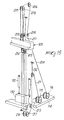
- figure 1 is a schematic view of an apparatus for performing the process;
- figure 2 is a partially sectional lateral elevation view of a detail of the apparatus;
- figure 3 is a frontal elevation view of the disaggregation tool;
- figure 4 is a plan view of a detail of the disaggregation tool;
- figure 5 is a partial sectional view of the tool taken along the section line V-V of figure 4;
- figure 6 is a schematic view of an apparatus according to a variated embodiment of the invention;
- figure 7 is a partially sectional frontal elevation view of the top of the shaft of the apparatus of figure 6;
- figure 8 is a partially sectional view of an intermediate section of the shaft of the apparatus of figure 6;
- figure 9 is a sectional view of the shaft section taken along the section line IX-IX of figure 8;
- figure 10 is a frontal elevation view of the element for the rotary motorization of the shaft;
- figure 11 is a partially sectional view taken along the section line XI-XI of figure 10;
- figure 12 is a lateral elevation view of the disaggregation-mixing tool;
- figure 13 is a partial sectional view of the disaggregation-mixing tool taken along the section line XIII-XIII of figure 12;
- figure 14 is a partially sectional view, taken along the section line XIV-XIV of figure 12, and
- figure 15 is a perspective view of the means which allow the penetration of the disaggregation-mixing tool into the soil and the lifting of said tool out of said soil.
- With reference to figures 1-5, the apparatus is generally indicated by the reference numeral 1 and comprises a self-propelled tracked
vehicle 2 provided with a control and operation cabin in which an operator is accommodated. An arm 3 is frontally mounted on thevehicle 2, is supported by tension elements 4 and supports atower 5. The vertical elevation of thetower 5 is controlled by arms 6 which connect its lower end to thevehicle 2. - A
shaft 7 is slidably and rotatably supported on thetower 5; during the operating steps, said shaft is actuated by means of a motorization unit 8 which is slidable along thetower 5. Theshaft 7 is composed of a plurality of individualtubular sections 9 which are mutually connected longitudinally. The sections, as can be seen in figure 2, are composed of anouter tube 10 inside which aninner tube 11 is arranged coaxially. The ends of thesection 9 are shaped so as to constitute couplings 11a, 11b which allow the axial connection of various sections. - The
tubes outer duct 12 and aninner duct 13 which are mutually separated. - A disaggregation-mixing tool, generally indicated by the
reference numeral 15 in figure 3, is rigidly associated with the lower end of theshaft 7 by means of acoupling 14. The disaggregation tool comprises a pair of diametrically oppositelower blades 16 and atubular element 17, which constitutes the central part of said tool and has a cutting head 17a at its lower end. - The
blades 16 are tile-shaped andteeth 18, suitable for excavating and moving the soil, are rigidly associated with their lower edge. Said teeth are arranged tangentially with respect to the axis of rotation of theshaft 7.Holes 19 are defined below theblades 16 and are connected to theinner duct 13, whereasholes 20 are defined above the blades and are connected to theouter duct 12. - A pair of
radial wings 21 is fixed on theelement 17 above theblades 16, and their function is to keep the soil under agitation during the perforation step, as will become apparent hereinafter. - A further pair of
blades 22 is arranged above thewings 21. Said upper blades have the same structure as theblades 16, andholes ducts - The
inner duct 13 of theshaft 7 is fed from above, through theexternal tube 25, with the consolidating agent, in particular pulverized cement, by theunit 26 which is formed by acement silo 27 and by anair compressor 28. Theouter duct 12 of theshaft 7 is fed, in an upward position, with water through thetube 29. The water is drawn from astorage tank 30 by means of apump 31 which sends the excess water of the hydration process back to the tank by means of areturn tube 32. - The described apparatus operates in the following manner.
- In a first step, the disaggregation tool is placed on the region of the soil to be treated and the verticality of the tower is checked.
- Then perforation of the soil begins with the preset rotation and advancement parameters, rotating the
tool 15 with a rotation and advancement rate which is a function of the consistency of the soil. While thetool 15 penetrates into the soil, thecompressor 28 initially sends air through thetube 25 and theduct 13. The air enters the soil through theholes duct 13 free. - During the penetration of the tool in the soil, water is sent through the
tube 29 and theduct 12 only when dry or very hard layers, which prevent the normal advancement of the tool, are encountered. - The amount of pumped water must be such as to provide the necessary humidification of the dry layers being traversed and thus allow the subsequent hydration of the consolidating agent.
- Once the required depth has been reached, while the tool continues to rotate, the feeding of the consolidating agent starts; said agent passes through the
tube 25 and theinner duct 13 and enters the soil through theholes - Then the lifting of the tool begins, reversing the direction of rotation. In this manner the humidified soil is mixed with the pulverized cement, so that preset speed parameters, as a function of existing stoichiometric ratios, are respected in the lifting step as well.
- The advantage of this process is that the amount of water used reacts entirely with the consolidating agent and therefore greater stability is given to the treated soil by leaving no free water in the soil or on the surface.
- In the variated embodiment of the invention illustrated in figures 6 to 15, the reference numerals start from 101 to indicate a self-propelled tracked vehicle provided with a control and
operation cabin 102 in which the operator is accommodated. - An
arm 103 is articulately mounted frontally to thevehicle 101 and is supported bytension elements 104. Aslider 105 is mounted at the top of thearm 103 and slidably supports atower 106. The tower rests on the ground and is suspended from theslider 105 by means of ahydraulic jack 107. By inclining thearm 103 by means of thetension elements 104 it is possible to position thetower 106 with respect to thevehicle 101, whereas by actuating thejack 107 it is possible to raise and lower the tower to allow the vehicle to move to a new work site or to allow the spacing of the tower with respect to the vehicle when thearm 103 is inclined outward. A shaft, generally indicated by thereference numeral 108, extends frontally to the tower, i.e. on the opposite side with respect to theslider 105, and is rotatably suspended, with its upper end, from aledge 109 which is guided on thetower 106. - The
shaft 108 is guided, in a median position, within a guidingelement 110 which is suspended from theledge 109 by means of a cable (or chain) 110a and is also guided along thetower 106. Theshaft 108 is rotationally coupled, in a downward position, to arotary motorization element 111 which can be raised and lowered by a certain extent by means of a pair ofjacks 112 mounted to the sides of thetower 106. - The disaggregation-mixing tool, generally indicated by the
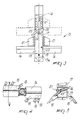
reference numeral 113, is applied to the lower end of theshaft 108 below themotorization element 111. The motorization element is guided along thetower 106 and is connected to the vehicle by abridge 114 on which twowinches ledge 109 with a closed-loop and synchronized traction and therefore raise or lower theshaft 108. - More in detail (see figure 7), the
ledge 109 is constituted by aplate 117 which is traversed by asleeve 118 which is rigidly associated with theplate 117 byribs 119. Asleeve 120 is arranged coaxially inside thesleeve 118 and is rotatably supported by means of a pair ofthrust bearings upper bearing 121 is retained between an internal shoulder of thesleeve 118 and a pair ofrings 123 which are screwed on a threaded portion of thesleeve 120. - A
cylindrical body 125 is centered on the top of thesleeve 118 and has aflange 126 which is traversed bybolts 127 which engage in acollar 128 of the sleeve for the mechanical coupling of the twoparts - The
cylindrical body 125 has alower seat 129 in which thetapered end portion 131 of thesleeve 120 sealingly rotates by virtue of the interposition of agasket 130. Thesleeve 120 has, in a downward position, aflange 132 which defines the seat for thebearing 122 and extends externally to thesleeve 118. Adisk 133 is centered on theflange 132 and centrally comprises atube 134 which rises coaxially inside thesleeve 120 and delimits therewith an annular chamber orinterspace 135. - The
flange 136 of amale element 137 of a coupling of theshaft 108 is associated with thedisk 133 in a downward position. Thedisk 133 is secured between theflanges bolts 138. Rubber rings 139, 140 ensure the necessary outward seal. Acavity 141 is defined in thedisk 133 and is connected, throughpassages 142, to theannular chamber 135. Achannel 143 extends from thecavity 141 and, by means of aconnection 144 fitted in theflange 136, leads outward so as to connect to aduct 165 which is specified hereinafter. - The
tube 134 extends upward beyond the taperedportion 131 of thesleeve 120 with a reduced-diameter portion 145 which sealingly rotates in twoseats cylindrical body 125 which are termed respectively intermediate seat and upper seat. -
Sealing gaskets portion 145 and theseats openings 150 are defined between theseats gaskets cylinder 125 and of theportion 145 of thetube 134. - The
tube 134 is connected to a supply of compressed air and to a supply of a consolidating agent (for example cement) by means of astationary tube 151 which has aflange 152 bolted on the head of thecylindrical body 125. The seal between thetube 151 and therotatable tube 134 is ensured by agasket 153 which is interposed between the opposite ends of thetube 151 and of theportion 145. - The
annular chamber 135 is connected to a water supply through ahole 154 defined radially in thebody 125 between thelower seat 130 and theintermediate seat 146. - The
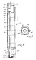
shaft 108, which is to be connected to themale element 137, is constituted by a plurality oftubular sections 155, one of which is shown in figures 8 and 9. Said section comprises anexternal tube 156 which has a square cross section with rounded corners; afemale element 157, shaped complementarily with respect to themale element 137, is inserted at the top of saidtube 156. - For this purpose, the
female element 157 has a cavity in which a cylindrical seat 158 is defined for accommodating acylindrical portion 159 of themale element 137 and asquare seat 160 for receiving thesquare portion 161 of themale element 137. Whereas a prismatic coupling is defined between theseat 160 and theportion 161 and allows the rotary coupling between thesection 155 and theelement 137, a hydraulic coupling is defined between the seat 158 and theportion 159 and is sealed by sealingrings 162. - In order to prevent the axial extraction of the
section 155,semi-cylindrical grooves seat 160 and respectively of theportion 161; when theelements duct 165 is welded externally to thetube 156 along a median line of a face and extends substantially along the entire length of thesection 155. Theduct 165 is connected to theunion 144 in an upward position with the addition of asleeve 166, and is connected to theduct 165 of the subsequent sections in a downward position by means offurther sleeves 167. - A
cylindrical tube 168 is arranged in tangential contact inside thesquare tube 156, and a furthercoaxial tube 169 is arranged inside it.Said tube 169 is centered, in an upward position, in a bush 170 which is inserted in thefemale element 157 and is centered, in a downward position, in abush 171 which is inserted in amale element 172 which closes thesection 155 downward. Thebushes 170, 171 are axially locked by Seeger rings 170a and 171a and are sealingly coupled in the respective seats by rubber rings 170b and 171b. - The
male element 172 is fully similar to themale element 137 described above and is therefore shaped so as to mechanically and hydraulically couple to a successive female element. - The disaggregation-mixing
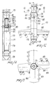
tool 113 is associated with the end of the last of thesections 155 which compose theshaft 108 and comprises a tubular element which is provided, in an upward position, with a female coupling element 173 (see figures 12-14) suitable for coupling to amale element 172. Asleeve 174 is rigidly associated with theelement 173 and extends downward with acylindrical jacket 175 in which afurther sleeve 176 is centered. Acylindrical shaft 177 is inserted in thesleeves head 178 is fixed to the lower end of said shaft. Theshaft 177 is keyed in thesleeve 176 by a throughpin 179, whereas it defines, at the top, a cylindrical cup 180 which is open toward thecavity 181 of theelement 173, with which it is connected by means of a bush 180a. The bush 180a is retained by aSeeger ring 180b and is sealingly inserted in its seat by means of rubber rings 180C, so that when themale element 172 of theoverlying section 155 is inserted in the cavity 182 a connection with thetube 169 is provided. Tworadial holes 182 extend from the cup 180 and traverse the wall of thesleeve 174;respective nozzles 183 are inserted in said holes. - A pair of
blades 184 is welded to thesleeve 174; said blades are arranged diametrically and are inclined forward and downward with respect to a counterclockwise direction of rotation. A plurality ofdisaggregation teeth 185 is welded on the front edge of theblades 184, andrespective wings 186 are welded on the rear edge and delimit acavity 187 which is open downward and at which thenozzles 183 are located. A similar pair ofblades 188 withteeth 189 is welded diametrically to thesleeve 176 but is angularly offset by 90 degrees with respect to theblades 184, so that theblades - When the
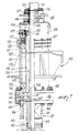
section 155 is inserted in thecavity 181, theduct 165 is connected through asleeve 167 to atubular element 190 which is rigidly associated externally to theelement 173 and ends with anozzle 191 which is directed downward and is located at the level of the pair ofupper blades 184. - The motorization or propulsion element 111 (see figure 10) comprises a
slider 192 which is guided along thetower 106 and is movable by means ofjacks 112. Anannular ledge 193 is protrudingly mounted on theslider 192 and amotor unit 194, which is axially traversed by theshaft 108, is applied thereto in an upward position. - The
motor unit 194, which is not illustrated in detail since it is of a conventional hydraulically-operated type, comprises atraction block 195 which axially guides and exerts a traction on theshaft 108. Thetraction block 195 is composed of a fifth wheel 196 (see figure 11) on which pairs ofwings 197 are welded at the faces of thetube 156. - Each pair of
wings 197 rotatably supports, by means of the interposition of bearings, aroller 198 which is slightly cambered at the center. - The
roller 198, which is opposite to theduct 165, has amedian groove 199 which allows the passage of said duct. Adome 200 is rigidly associated with theledge 193 in a downward position and encloses the disaggregation-mixingtool 113, with respect to which is can be raised and lowered when theslider 192 is actuated by thejack 112. - The top of the
dome 200 is constituted by aplate 201 which defines acylindrical seat 202 for the rotatable accommodation of tworings 203 which circumscribe thetube 156 with a prismatic engagement. Therings 203 have the function of scraping any material which adheres to the walls of theshaft 108 when said shaft is caused to slide through themotorization unit 111. - A double cable system is provided for the lifting and lowering of the
shaft 108 and can be actuated, as mentioned, by means of twowinches bridge 114. The winch 116 (see figure 15) acts on acable 204 which is wrapped around a plurality of pulleys 205-210 and has its end connected to thetower 106. Thepulley 205 is rotatably supported on theslider 105, whereas the pulleys 206-208 are mounted at the top of thetower 106 and form a tackle with the pulleys 209-210 which are mounted on theledge 109. Thewinch 115 acts on thecable 211, the end whereof is connected to the base of the tower. Thecable 211 is wrapped around a pair of transmission pulleys 212, 213 and around two pairs of pulleys 214-217. Thepulleys slider 105 and at the lower end of thetower 106. The pair ofpulleys ledge 109 and forms a further tackle together with the pair ofpulleys tower 106. - The described apparatus operates in the same manner as the preceding one, the only difference being that the compressed air, the humidification water and the consolidating agent are injected into the soil during the perforation and the rise of the tool, through the
same nozzles 183. - A considerable advantage of the apparatus of figures 6-15 is the fact that the ducts for the water and air and for the consolidating agent remain constantly separated, so that there is no possibility of mixing the two flows. If wear should occur at the
seals openings 150 of thecylindrical body 125 and be detected by the assigned personnel. - The structure of the
sections 155 and of the rotatable coupling, by means of which the ducts for water, air and consolidating agent are connected to stationary ducts, is particularly important. Theinner ducts disk 133 or the ring 171b in order to extract thetubes nozzles 183 by removing thepin 179 and then extracting thecylindrical shaft 177 from below. - A further advantage of the present invention is constituted by the
dome 200, by virtue of which it is possible to prevent the dust produced when the disaggregation-mixing tool approaches the surface of the soil during its upward stroke from being scattered around with considerable disadvantages from the point of view of environmental impact. It should be noted that the dome can be raised by means of thejacks 112 to allow, if required, inspection of the disaggregation-mixingtool 113. - Further modifications and variations are possible in the practical embodiment of the invention.
- One of them provides, for the
tube 156, a non-square cross section, for example a triangular or hexagonal or even circular one with outer longitudinal strips acting as keys. In a further embodiment, theduct 165 is located inside thetube 156 at the chambers defined between theinner tube 168 and thetube 156. - In the practical embodiment of the invention, it is possible to provide the duplication of the
shafts 108 and of thetools 113 so as to simultaneously produce two columns of consolidated soil. - Where technical features mentioned in any claim are followed by reference signs, those reference signs have been included for the sole purpose of increasing the intelligibility of the claims and accordingly such reference signs do not have any limiting effect on the scope of each element identified by way of example by such reference signs.
Claims (12)
Applications Claiming Priority (4)
| Application Number | Priority Date | Filing Date | Title |
|---|---|---|---|
| IT8903592A IT8903592A0 (en) | 1989-08-03 | 1989-08-03 | PROCEDURE FOR THE CONSOLIDATION OF LAND |
| IT359289 | 1989-08-03 | ||
| IT00348890A IT1242644B (en) | 1990-05-08 | 1990-05-08 | Equipment for soil consolidation |
| IT348890 | 1990-05-08 |
Publications (3)
| Publication Number | Publication Date |
|---|---|
| EP0411560A2 true EP0411560A2 (en) | 1991-02-06 |
| EP0411560A3 EP0411560A3 (en) | 1991-03-13 |
| EP0411560B1 EP0411560B1 (en) | 1994-05-04 |
Family
ID=26325411
Family Applications (1)
| Application Number | Title | Priority Date | Filing Date |
|---|---|---|---|
| EP19900114666 Expired - Lifetime EP0411560B1 (en) | 1989-08-03 | 1990-07-31 | Apparatus for consolidating soil |
Country Status (3)
| Country | Link |
|---|---|
| EP (1) | EP0411560B1 (en) |
| DE (1) | DE69008641T2 (en) |
| ES (1) | ES2055835T3 (en) |
Cited By (8)
| Publication number | Priority date | Publication date | Assignee | Title |
|---|---|---|---|---|
| GB2253424A (en) * | 1991-03-08 | 1992-09-09 | Sicapi Italiana Spa | Soil consolidation |
| WO1993002257A1 (en) * | 1991-07-18 | 1993-02-04 | Bpa Byggproduktion Ab | Tool for introducing soil stabilizing material |
| ES2125116A1 (en) * | 1992-01-28 | 1999-02-16 | Sicapi Italiana Spa | Improvements to the subject of patent P 9200171 for installation for consolidating columns of soil by means of the forced introduction of inert elements |
| WO2000026477A1 (en) * | 1998-10-30 | 2000-05-11 | Junttan Oy | Method for stabilizing the ground and apparatus for applying the method |
| US6517292B1 (en) * | 1999-09-01 | 2003-02-11 | Richard E Landau | Apparatus to form columns of granular material |
| EP1748110A3 (en) * | 2005-07-22 | 2008-09-10 | SOILMEC S.p.A. | Method and device for mixing earth in situ for the formation of underground walls or diaphragms |
| RU2392381C2 (en) * | 2004-07-26 | 2010-06-20 | Йохан М. ГЮНТЕР | Method for fabrication of drilled pile in clay soil |
| EP2395153A1 (en) * | 2010-06-11 | 2011-12-14 | Bauer Spezialtiefbau GmbH | Device and method for manufacturing wall panels in the floor |
Families Citing this family (2)
| Publication number | Priority date | Publication date | Assignee | Title |
|---|---|---|---|---|
| US7341405B2 (en) | 2006-02-13 | 2008-03-11 | Gunther Johan M | In-situ pilings with consistent properties from top to bottom and minimal voids |
| CN107476774B (en) * | 2017-08-28 | 2019-10-25 | 中国葛洲坝集团市政工程有限公司 | The processing method of burying in a kind of drill-pouring work progress mesoporous |
Family Cites Families (4)
| Publication number | Priority date | Publication date | Assignee | Title |
|---|---|---|---|---|
| GB1374705A (en) * | 1971-05-11 | 1974-11-20 | Linden Alimak Ab | Implement for stabilising cohesive and friable earths |
| JPS5532849A (en) * | 1978-08-30 | 1980-03-07 | Sato Kogyo Kk | Grouting method |
| DE2938564A1 (en) * | 1979-09-24 | 1981-04-09 | Sanwa Kizai K.K., Tokyo | EARTH DRILL |
| JPS60164509A (en) * | 1984-02-02 | 1985-08-27 | Kobe Steel Ltd | Method and apparatus for improving ground by jet stirring of powder |
-
1990
- 1990-07-31 ES ES90114666T patent/ES2055835T3/en not_active Expired - Lifetime
- 1990-07-31 EP EP19900114666 patent/EP0411560B1/en not_active Expired - Lifetime
- 1990-07-31 DE DE1990608641 patent/DE69008641T2/en not_active Expired - Fee Related
Cited By (13)
| Publication number | Priority date | Publication date | Assignee | Title |
|---|---|---|---|---|
| GB2253424A (en) * | 1991-03-08 | 1992-09-09 | Sicapi Italiana Spa | Soil consolidation |
| FR2673652A1 (en) * | 1991-03-08 | 1992-09-11 | Sicapi Italiana Spa | System and apparatus for constructing columns for consolidation in ground |
| GB2253424B (en) * | 1991-03-08 | 1994-11-02 | Sicapi Italiana Spa | Method and apparatus for consolidating columns of terrain |
| ES2065795A2 (en) * | 1991-03-08 | 1995-02-16 | Sicapi Italiana Spa | Soil consolidation |
| WO1993002257A1 (en) * | 1991-07-18 | 1993-02-04 | Bpa Byggproduktion Ab | Tool for introducing soil stabilizing material |
| ES2125116A1 (en) * | 1992-01-28 | 1999-02-16 | Sicapi Italiana Spa | Improvements to the subject of patent P 9200171 for installation for consolidating columns of soil by means of the forced introduction of inert elements |
| WO2000026477A1 (en) * | 1998-10-30 | 2000-05-11 | Junttan Oy | Method for stabilizing the ground and apparatus for applying the method |
| US6517292B1 (en) * | 1999-09-01 | 2003-02-11 | Richard E Landau | Apparatus to form columns of granular material |
| RU2392381C2 (en) * | 2004-07-26 | 2010-06-20 | Йохан М. ГЮНТЕР | Method for fabrication of drilled pile in clay soil |
| AU2005269461B2 (en) * | 2004-07-26 | 2010-08-05 | Johan M. Gunther | Process to prepare in-situ pilings in clay soil |
| NO340102B1 (en) * | 2004-07-26 | 2017-03-13 | Johan M Gunther | Procedure for preparing in situ pellets in clay soil |
| EP1748110A3 (en) * | 2005-07-22 | 2008-09-10 | SOILMEC S.p.A. | Method and device for mixing earth in situ for the formation of underground walls or diaphragms |
| EP2395153A1 (en) * | 2010-06-11 | 2011-12-14 | Bauer Spezialtiefbau GmbH | Device and method for manufacturing wall panels in the floor |
Also Published As
| Publication number | Publication date |
|---|---|
| EP0411560A3 (en) | 1991-03-13 |
| DE69008641D1 (en) | 1994-06-09 |
| DE69008641T2 (en) | 1994-08-25 |
| ES2055835T3 (en) | 1994-09-01 |
| EP0411560B1 (en) | 1994-05-04 |
Similar Documents
| Publication | Publication Date | Title |
|---|---|---|
| US4035024A (en) | Hard rock trench cutting machine | |
| US4077671A (en) | Subterranean drilling and slurry mining method | |
| CN112253129B (en) | Full-automatic shaft shield constructs equipment | |
| CA2974615C (en) | Shaft enlargement arrangement for a boring system | |
| US4904119A (en) | Process for placing a piling in the ground, a drilling machine and an arrangement for implementing this process | |
| US2675213A (en) | Horizontal earth boring machine | |
| EP0411560A2 (en) | Apparatus for consolidating soil | |
| US7510025B2 (en) | Boring machine | |
| US3775805A (en) | Clearing solid material from elongate tubes and passages | |
| CN109339813A (en) | A kind of pipe jacking tunnelling machine | |
| US4189186A (en) | Tunneling machine | |
| CN111140170A (en) | Complete equipment for transverse large-diameter hole forming in coal pillar area of soft coal seam and hole forming process | |
| US4298230A (en) | Tunnelling apparatus | |
| CN215860187U (en) | Tunneling device of tunnel boring machine and tunnel boring machine | |
| US3912024A (en) | Power train for horizontal earth boring machine | |
| US3236315A (en) | Auger mining machine | |
| US2647726A (en) | Horizontal earth boring machine | |
| US4076087A (en) | Hole reamer | |
| CN213775376U (en) | Full-automatic shaft shield constructs machine | |
| US2786284A (en) | Marsh ditcher | |
| GB2091316A (en) | Tunnelling | |
| EP0716190A1 (en) | Slotting mill | |
| EP0772730B1 (en) | Driving shield | |
| JP3837714B2 (en) | Ground improvement column body making machine | |
| US4059965A (en) | Apparatus for and a method of laying a pipe line |
Legal Events
| Date | Code | Title | Description |
|---|---|---|---|
| PUAI | Public reference made under article 153(3) epc to a published international application that has entered the european phase |
Free format text: ORIGINAL CODE: 0009012 |
|
| PUAL | Search report despatched |
Free format text: ORIGINAL CODE: 0009013 |
|
| AK | Designated contracting states |
Kind code of ref document: A2 Designated state(s): DE ES FR GB |
|
| AK | Designated contracting states |
Kind code of ref document: A3 Designated state(s): DE ES FR GB |
|
| RHK1 | Main classification (correction) |
Ipc: E02D 3/12 |
|
| RHK1 | Main classification (correction) |
Ipc: E02D 3/12 |
|
| 17P | Request for examination filed |
Effective date: 19910906 |
|
| 17Q | First examination report despatched |
Effective date: 19920910 |
|
| GRAA | (expected) grant |
Free format text: ORIGINAL CODE: 0009210 |
|
| AK | Designated contracting states |
Kind code of ref document: B1 Designated state(s): DE ES FR GB |
|
| REF | Corresponds to: |
Ref document number: 69008641 Country of ref document: DE Date of ref document: 19940609 |
|
| ET | Fr: translation filed | ||
| REG | Reference to a national code |
Ref country code: ES Ref legal event code: FG2A Ref document number: 2055835 Country of ref document: ES Kind code of ref document: T3 |
|
| PLBE | No opposition filed within time limit |
Free format text: ORIGINAL CODE: 0009261 |
|
| STAA | Information on the status of an ep patent application or granted ep patent |
Free format text: STATUS: NO OPPOSITION FILED WITHIN TIME LIMIT |
|
| 26N | No opposition filed | ||
| REG | Reference to a national code |
Ref country code: GB Ref legal event code: IF02 |
|
| PGFP | Annual fee paid to national office [announced via postgrant information from national office to epo] |
Ref country code: ES Payment date: 20080715 Year of fee payment: 19 Ref country code: DE Payment date: 20080917 Year of fee payment: 19 |
|
| PGFP | Annual fee paid to national office [announced via postgrant information from national office to epo] |
Ref country code: FR Payment date: 20080725 Year of fee payment: 19 |
|
| PGFP | Annual fee paid to national office [announced via postgrant information from national office to epo] |
Ref country code: GB Payment date: 20080729 Year of fee payment: 19 |
|
| GBPC | Gb: european patent ceased through non-payment of renewal fee |
Effective date: 20090731 |
|
| REG | Reference to a national code |
Ref country code: FR Ref legal event code: ST Effective date: 20100331 |
|
| PG25 | Lapsed in a contracting state [announced via postgrant information from national office to epo] |
Ref country code: FR Free format text: LAPSE BECAUSE OF NON-PAYMENT OF DUE FEES Effective date: 20090731 |
|
| PG25 | Lapsed in a contracting state [announced via postgrant information from national office to epo] |
Ref country code: GB Free format text: LAPSE BECAUSE OF NON-PAYMENT OF DUE FEES Effective date: 20090731 |
|
| PG25 | Lapsed in a contracting state [announced via postgrant information from national office to epo] |
Ref country code: DE Free format text: LAPSE BECAUSE OF NON-PAYMENT OF DUE FEES Effective date: 20100202 |
|
| REG | Reference to a national code |
Ref country code: ES Ref legal event code: FD2A Effective date: 20090801 |
|
| PG25 | Lapsed in a contracting state [announced via postgrant information from national office to epo] |
Ref country code: ES Free format text: LAPSE BECAUSE OF NON-PAYMENT OF DUE FEES Effective date: 20090801 |