EP0411846A2 - Méthode de fabrication et installation pour revêtir des éléments structuraux de véhicules - Google Patents
Méthode de fabrication et installation pour revêtir des éléments structuraux de véhicules Download PDFInfo
- Publication number
- EP0411846A2 EP0411846A2 EP90308306A EP90308306A EP0411846A2 EP 0411846 A2 EP0411846 A2 EP 0411846A2 EP 90308306 A EP90308306 A EP 90308306A EP 90308306 A EP90308306 A EP 90308306A EP 0411846 A2 EP0411846 A2 EP 0411846A2
- Authority
- EP
- European Patent Office
- Prior art keywords
- station
- vehicle structural
- structural component
- arm
- coating
- Prior art date
- Legal status (The legal status is an assumption and is not a legal conclusion. Google has not performed a legal analysis and makes no representation as to the accuracy of the status listed.)
- Granted
Links
Images


Classifications
-
- B—PERFORMING OPERATIONS; TRANSPORTING
- B05—SPRAYING OR ATOMISING IN GENERAL; APPLYING FLUENT MATERIALS TO SURFACES, IN GENERAL
- B05B—SPRAYING APPARATUS; ATOMISING APPARATUS; NOZZLES
- B05B13/00—Machines or plants for applying liquids or other fluent materials to surfaces of objects or other work by spraying, not covered by groups B05B1/00 - B05B11/00
- B05B13/02—Means for supporting work; Arrangement or mounting of spray heads; Adaptation or arrangement of means for feeding work
- B05B13/0221—Means for supporting work; Arrangement or mounting of spray heads; Adaptation or arrangement of means for feeding work characterised by the means for moving or conveying the objects or other work, e.g. conveyor belts
- B05B13/0242—Means for supporting work; Arrangement or mounting of spray heads; Adaptation or arrangement of means for feeding work characterised by the means for moving or conveying the objects or other work, e.g. conveyor belts the objects being individually presented to the spray heads by a rotating element, e.g. turntable
-
- B—PERFORMING OPERATIONS; TRANSPORTING
- B05—SPRAYING OR ATOMISING IN GENERAL; APPLYING FLUENT MATERIALS TO SURFACES, IN GENERAL
- B05C—APPARATUS FOR APPLYING FLUENT MATERIALS TO SURFACES, IN GENERAL
- B05C3/00—Apparatus in which the work is brought into contact with a bulk quantity of liquid or other fluent material
- B05C3/02—Apparatus in which the work is brought into contact with a bulk quantity of liquid or other fluent material the work being immersed in the liquid or other fluent material
- B05C3/09—Apparatus in which the work is brought into contact with a bulk quantity of liquid or other fluent material the work being immersed in the liquid or other fluent material for treating separate articles
Definitions
- the present invention relates to manufacturing methods and facilities for applying a coating to vehicle structural components, including the application of a hot melt wax coating to vehicle frames for protection against rust and corrosion.
- the present invention arose during development efforts directed toward reducing the high capital expense of a manufacturing facility for coating vehicle structural components such as frames.
- Vehicle manufacturers are more commonly requiring vendors and parts suppliers to have local on-site manufacturing or processing facilities coordinating with the assembly operation of the vehicle manufacturer.
- suppliers providing vehicle structural components such as frames, this requires erection of a coating facility at each of the various satellite assembly facilities.
- erection of multiple satellite coating facilities is not cost effective due to the extremely high capital expense of same.
- a vehicle frame is a generally flat longitudinal structural member which in one exemplary size has a longitudinal length of about 178 inches, a lateral width of about 42 inches, and a height of about 16 inches, though the dimensions may of course vary.
- Prior facilities for applying a hot melt wax coating to such frames typically require buildings of about 2 million cubic feet, with 50,000 square feet of lateral area and over 60 feet in height.
- the frames are hung vertically and transported to a dipping tank and dipped downwardly into the tank for coating the frame in the hot melt wax liquid, and then raised out of the tank.
- the building must be at least twice as high as the longitudinal length of the frame.
- the tank volume is about 63,000 gallons.
- the building is heated by ovens or the like such that the heated air in the building preheats the frames prior to dipping, to enhance the coating during the dip into the hot melt wax liquid tank.
- Preheating of the frames with air is inefficient and requires long preheat times.
- the vertical hanging of the frames also requires large openings into and out of the building, causing significant heat loss and energy inefficiency.
- the construction cost of the building is high because of its special requirements. Furthermore, the building has no other use.
- the present invention addresses and solves the above noted problems with a simple and effective manufacturing method and facility.
- the invention reduces the building volume by a factor of 10 or more, e.g. the new building can be reduced to as little as 5% of the volume of the prior building.
- the invention also reduces the tank volume requirements for the coating liquid to as little as 4%, e.g. to as low as 2,000 gallons instead of the 63,000 gallons required for the above noted prior tank. This saves wax cost.
- the invention also significantly reduces the height requirement of the tank, e.g. from about 25 feet deep to about 25 inches deep. This desirably solves problems of hydrostatic fluid pressure and leakage caused thereby at the bottom of the tank.
- the construction cost of the building is reduced by a factor of about 10 due to the reduced special requirements of the building and also due to reduced loading capability of the building due to special transport structure within the building in accordance with the invention for carrying the vehicle structural components.
- the building is adaptable to other uses in the event of changing requirements.
- the transport mechanism and core within the building can be moved to other buildings and locations.
- FIG. 1 shows a manufacturing facility 20 with substantially reduced space requirements for applying a coating to vehicle structural components such as frames 22, 24, and the like.
- the facility includes a building 26 housing a central rotary carousel 28 having a central hub 30 rotatable about a vertical axis and having a plurality of arms 32, 34, etc. thereon.
- Building 26 also houses a loading station 36, a coating station 38 having coating liquid 40 in tank 42, and an unloading station 44, all spaced peripherally around hub 30 such that rotation of hub 30 moves the arms to the various stations.
- Building 26 also houses a preheat wash station 46, a rinse station 48, and a post heat drip station 50.
- Preheat wash station 46 includes a tank 52 with a wash liquid 54 at an elevated temperature.
- Rinse station 48 includes a tank 56 with a rinse liquid 58 at an elevated temperature.
- the preheat wash and rinse stations preheat the frame by liquid heat transfer, to enhance the hot melt wax coating at station 38 when the frame is dipped into the hot melt wax coating liquid 40, to be described.
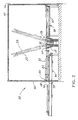
- Arm 32 moves downwardly, FIG. 2, at loading station 36 to engage frame 22 and then moves upwardly to lift the frame and carry the frame during rotation of hub 30.
- the arm moves downwardly at each of stations 46, 48 and 38 to lower the frame into the liquid in the respective tank, and then moves upwardly to raise the frame out of such liquid in the respective tank.
- the arm moves downwardly at unloading station 44 to disengage the frame and then moves upwardly and rotates to loading station 36, to begin the next cycle.
- Arm 32 swings in an arc about pivot point 60 at hub 30, and is actuated between its upwardly raised position as shown in phantom line and its downwardly lowered position as shown in solid line by a hydraulic cylinder 62, or alternatively is pneumatically actuated, or is raised and lowered by a cable, chain, or the like.
- Frame 22 at loading station 36 is attached in a generally horizontal position to arm 32.
- the frame is likewise detached in a generally horizontal position from the arm at unloading station 44.
- the frame is lowered by the arm into the respective tanks at stations 46, 48 and 38 in a generally horizontal position in the respective tank.
- the horizontal loading, dipped and unloading positions of the frame are all substantially coplanar.
- Frame 22 has a longitudinal extent of a given length. As seen in FIG. 2, building 26 has a height to roof 64 substantially less than twice the length of frame 22.
- the transport mechanism provided by carousel 28 moves frame 22 through stations 36, 46, 48, 38 and 44 such that the longitudinal extent of frame 22 is substantially horizontal.
- the raising and lowering of frame 22 into and out of the tanks at stations 46, 48 and 38 defines a travel path having a vertical height substantially less than twice the length of the frame.
- Building 26 has a sidewall 66 with an entrance opening 68 therethrough, FIGS. 1, 2 and 11, at loading station 36, and an exit opening 70 therethrough at unloading station 44.
- Frame 22 is passed longitudinally through such openings in a generally horizontal position into and out of building 26, such that openings 68 and 70 have minimum dimensions, to minimize heat loss from the building.
- uncoated excess liquid is allowed to drip from the frame. Additionally or alternatively, uncoated excess liquid is allowed to drip from the frame above tank 42 at coating station 38.
- the amount of pivoting of the transport arm varies the tilt angle, to provide an adjustable drip angle of the frame. This is particularly desirable because it enables a selectively chosen drip angle, which in some instances may be vertical, or in other instances at a diagonal angle relative to horizontal. The latter is preferred to prevent drips from one of the lateral cross pieces of the frame from dripping onto another lateral cross piece therebelow.
- the pivoted transport arm thus moves the frame through the coating station into and out of contact with the coating liquid and raises the frame after such coating to a tilted position such that the longitudinal extent of the frame is tilted at an angle relative to horizontal.
- Hands 72, 74, 76, 78, FIGS. 3 and 4 extend from arm 32 and have fingers 80, 82, 84, 86, 88, 90, 92, 94 engaging frame 22.
- Frame 22 is attached to the fingers at loading station 36.
- a conveyance mechanism provided by continuous belt conveyor 96 carries frame 22 longitudinally horizontally through flexible hanging leaves 98 at opening 68 in building wall 66 to loading station 36.
- Conveyor 96 carries frame 22 rightwardly, FIGS. 1-4, to a first position. Arm 32 is swung downwardly, with at least some of the noted fingers moving downwardly past and below frame 22.
- Conveyor 96 then carries frame 22 further rightwardly, advancing frame 22 to a second position above the last mentioned fingers, such that upon swinging arm 32 upwardly, such last mentioned fingers engage the underside of frame 22 and lift same.
- Frame 22 is a generally flat planar member having a pair of longitudinal sides 100 and 102, FIG. 3, and a plurality of lateral cross pieces such as 104, 106, 108, 110, 112. Fingers 80 and 84 engage the underside of cross piece 104. Fingers 82 and 86 engage the underside of longitudinal sides 100 and 102, respectively. Fingers 88 and 92 engage the underside of cross piece 112. Fingers 90 and 94 engage the top side of longitudinal sides 100 and 102, respectively. The noted engagement locates the longitudinal sides of the frame and the respective cross pieces of the frame, to precisely locate the frame both longitudinally and laterally.
- the fingers are formed with a knife edge laterally crossing the respective portion of the frame, for example as shown at knife edges 114 and 116 for respective fingers 80 and 82 in FIGS. 6 and 7, and knife edges 118 and 120 for respective fingers 88 and 90 in FIGS. 8-10.
- the lower fingers 80, 84, 88, 92 are slightly angled, such that when arm 32 is in the lowered position, the lower fingers tilt upwardly leftwardly and engage only an edge of the frame to provide only point contact therewith, to enhance the coating of the frame.
- the lateral lower fingers 82 and 86 and the lateral upper fingers 90 and 94 extend laterally across the longitudinal sides of the frame and are likewise angled, as shown in FIGS. 7 for finger 82, and in FIGS.
- finger 90 has an upwardly extending portion 121 facilitating stacking of frames.
- two or more frames are carried on carousel arm 32, such that two or more frames are dipped during each dipping step, etc.
- edge 120 does not engage the top of the frame therebelow, but rather locates the siderails of the frame outboard thereof, and edge 121 is spaced slightly inwardly of the frame siderail.
- Stationary V-shaped structure 122 is provided at loading station 36 and spaced above conveyor 96 and is engaged by arm 32 during downward swinging of the arm to guide and locate the arm relative to conveyor 96 and frame 22.
- Conveyor 96 has a plurality of cones 124, 126, 128, 130, etc., thereon, with angled bevel surfaces forming knife edges such as 132, FIGS. 3 and 5, which extend along a diagonal angle to provide point contact with the frame. Some of the cones such as cones 126 and 130 engage the longitudinal sides of the frame, and others of the cones such as cones 124 and 128 engage lateral cross pieces of the frame. The cones space the frame above conveyor 96 and precisely locate the frame both longitudinally and laterally.
- the frame has a plurality of holes in the underside thereof, and conveyor 96 has a plurality of cones extending upwardly partially through such holes and spacing the frame above the conveyor and precisely locating the frame both longitudinally and laterally.
- Unloading at station 44 is comparable but reversed in sequence from loading at station 36.
- a conveyor 134 is provided like conveyor 96.
- the transport arm of the carousel is lowered to lower the frame onto the cones on the conveyor.
- the above noted knife edges and angles on the fingers provide the noted point contact with the frame and minimize marring of the coating on the frame. In most applications, there is no marring because the hot melt wax coating heals itself, which healing is facilitated by the noted point contact, which minimizes the area which must be healed by continued flow of the hot melt wax coating after disengagement of the frame by the fingers.
- the above noted beveled surfaces and knife edges such as 132, FIG. 5, of the cones on the conveyor and the angles thereof desirably provide only point contact with the coated frame on exit conveyor 134.
- opening 70 is not provided with the hanging flexible leaves such as 98 of entrance opening 68, because such leaves would drag across and mar the coating on the frame. Instead, opening 70 is provided with a quick acting guillotine door 136, FIG. 12, actuated by pneumatic cylinder 138 to quickly move vertically upwardly and downwardly. This minimizes heat loss from the building.
- FIG. 13 shows a further embodiment, and like reference numerals are used from the above FIGS. where appropriate to facilitate clarity.
- Preheat wash and rinse stations 140 and 142 are external of building 144.
- Preheat wash station 140 includes a tank 146, a heater 148, a pump 150 supplying heated wash liquid to spray nozzles 152, and a return filter 154.
- Rinse station 142 is comparable for rinse liquid.
- Conveyor 96 conveys the frame horizontally longitudinally through stations 140 and 142 to provide liquid heat transfer to the frame, and then moves the frame into building 144. This movement is along the direction of the longitudinal extent of the frame.
- the frame is attached to pivot arm 32 as above described, and the arm swings upwardly to lift the frame from conveyor 96.
- Coating station 38 of FIG. 1 is replaced by a coating station 154 in FIG. 13 with a tank 156 which is substantially laterally expanded to extend along a significant portion of the inner periphery of the building around hub 30.
- tank 156 has a semicircular shape when viewed from above.
- Transport arm 32 lowers the frame into and out of tank 156, as above.
- Transport arm 32 also moves the frame horizontally through tank 156 in a direction transverse to the longitudinal extent of the frame.
- the lowering and raising of the frame into and out of the tank defines a travel path having a vertical height substantially less than twice the length of the frame, as before.
- a heater 158 and pump 160 are provided for heating and pumping coating liquid 162 to tank 156.
- Building 144 has differing heights at loading station 36 and the central portion of coating station 154. At loading station 136, the building must be high enough to allow arm 32 to pivot upwardly to lift the frame from conveyor 96. However, in the central portion of coating station 154, as shown on the right side of FIG. 14, arm 32 need only move horizontally laterally, and hence there is no need for any greater building height other than a small clearance for arm 32 above the tank.
- the roof of building 144 along this central portion of coating station 154 is provided by access doors 164. At the beginning of coating station 154, an increased building height is necessary as shown at roof 166 at the left side of FIG. 14, to accommodate movement of arm 32 in an upward position over tank 156 and then downward movement of arm 32 to lower the frame into tank 156.
- the building likewise has a higher roof at the end of coating section 154.
- the building thus has a first lower height at roof access door 164 over the middle of tank 156, and second higher heights as at roof 166 at the ends of the tank to permit downward and upward swinging of arm 32 to lower and raise the frame into and out of the tank.
- the unloading station may be provided within the building, as in FIG. 1, or an external loading station 168 may be provided with the frames remaining in a horizontal position but stacked vertically, and then periodically removed by a forklift 170 or the like.
- Building 144 has an external recess 169 formed in the periphery thereof at which unloading station 168 is located.
- a cam track is provided in the building to assist or eliminate the pivot arm actuators such as 62.
- FIG. 15 shows a cam track 172 extending at least partially peripherally around central hub 30.
- Arm 32 has a roller 174 engaging and rolling along the cam track during rotation of hub 30 such that arm 32 is lowered and raised according to the camming profile of the cam track.
- the cam track has a V-shape at loading station 136 such that roller 174 rides down the V to lower the arm to engage the frame.
- the cam track may be provided by the upper lip 176 of the tank having high lobes at the beginning and the end of the tank, and having an extended low lobe along the central portion of the tank.
- the horizontal circumferential length of the low lobe portion of the cam surface controls the length of horizontal travel of the frame in coating liquid 162 in tank 156 during rotation of hub 30, to control coating of the frame.
- FIG. 18 shows another embodiment, and uses like reference numerals from the above FIGS. where appropriate to facilitate clarity.
- a servicing station 180 is spaced along the periphery of hub 30.
- Building 182 has an opening 184 at station 180.
- the carousel pivot arm is movable to a lowered position at servicing station 180, passing through opening 184 in building 182 externally of the building to external servicing location 180 for servicing of the transport pivot arm.
- the arm is movable to an upward position at servicing station 180 remaining within building 182 and bypassing external servicing location 180 and instead passing within building 182 to the next station therein upon rotation of hub 30.
- Building 182 has an external recess 186 formed therein at servicing station 180 providing the external location for servicing of the pivot arm.
- the pivot arm when servicing is desired, the pivot arm is swung downwardly through opening 184 to permit servicing, and then pivoted back upwardly through opening 184 when the servicing is completed.
- This allows servicing of the pivot arm externally of the building, which is desirable because the servicing technican can remain outside the building and not have to work in the elevated temperatures within the building.
- the pivot arm When servicing is not desired, the pivot arm merely remains in its upward pivoted position at station 180 without passing through opening 184.
- FIG. 19 shows another embodiment, and like reference numerals are used from the above FIGS. where appropriate to facilitate clarity.
- Building 188 has an increased number of stations which may provide various desired combinations of preheat washing, rinsing, coating, and dripping between loading station 36 and unloading station 44.
- the carousel at the core of the building is supported independently of the building, and may be moved to different locations and buildings as desired.
- the motor drive for the hub may be provided at the hub within the building, or may be provided externally of the building with an outer ring for mechanical advantage enabling a smaller motor and saving the motor from the harsh environment and elevated temperatures within the building. While a single frame per pivot arm of the carousel is shown, each arm may carry and dip more than one frame at a time. For example, one frame may be carried above the arm, and another frame below the arm. Further alternatively, multiple frames may be stacked, and carried by an arm.
Landscapes
- Coating Apparatus (AREA)
- Spray Control Apparatus (AREA)
- Application Of Or Painting With Fluid Materials (AREA)
- Automobile Manufacture Line, Endless Track Vehicle, Trailer (AREA)
Applications Claiming Priority (2)
| Application Number | Priority Date | Filing Date | Title |
|---|---|---|---|
| US07/389,346 US5061529A (en) | 1989-08-03 | 1989-08-03 | Manufacturing method and facility for coating vehicle structural components |
| US389346 | 1989-08-03 |
Publications (3)
| Publication Number | Publication Date |
|---|---|
| EP0411846A2 true EP0411846A2 (fr) | 1991-02-06 |
| EP0411846A3 EP0411846A3 (en) | 1991-10-16 |
| EP0411846B1 EP0411846B1 (fr) | 1994-09-21 |
Family
ID=23537879
Family Applications (1)
| Application Number | Title | Priority Date | Filing Date |
|---|---|---|---|
| EP90308306A Expired - Lifetime EP0411846B1 (fr) | 1989-08-03 | 1990-07-30 | Méthode de fabrication et installation pour revêtir des éléments structuraux de véhicules |
Country Status (7)
| Country | Link |
|---|---|
| US (1) | US5061529A (fr) |
| EP (1) | EP0411846B1 (fr) |
| JP (1) | JP2635806B2 (fr) |
| CA (1) | CA2022319C (fr) |
| DE (1) | DE69012706T2 (fr) |
| ES (1) | ES2064646T3 (fr) |
| MX (1) | MX174106B (fr) |
Cited By (2)
| Publication number | Priority date | Publication date | Assignee | Title |
|---|---|---|---|---|
| US8453597B2 (en) | 2006-07-14 | 2013-06-04 | Dürr Systems GmbH | Paint shop and corresponding method of operation |
| CN105772301A (zh) * | 2016-05-16 | 2016-07-20 | 东莞市迪沙机电有限公司 | 内锅自动喷涂机 |
Families Citing this family (18)
| Publication number | Priority date | Publication date | Assignee | Title |
|---|---|---|---|---|
| US5264253A (en) * | 1989-08-03 | 1993-11-23 | A. O. Smith Corporation | Coating method and facility for vehicle structural components |
| US5090350A (en) * | 1989-12-27 | 1992-02-25 | Xerox Corporation | Method and apparatus for cleaning, coating and curing receptor substrates in an enclosed planetary array |
| US5153027A (en) * | 1991-06-10 | 1992-10-06 | Ford Motor Company | Preparation of differential thickness coatings by dip coating where the substrate is pivoted |
| JP2760189B2 (ja) * | 1991-11-08 | 1998-05-28 | 株式会社村田製作所 | チップ部品の電極形成装置 |
| JP4505736B2 (ja) * | 2005-01-28 | 2010-07-21 | 豊田合成株式会社 | 塗装機 |
| US8484930B2 (en) * | 2005-11-01 | 2013-07-16 | Phillip C. Ruehl | Boxed frame member and method for manufacture |
| EP1984636B1 (fr) * | 2006-02-01 | 2010-08-18 | AM General LLC | Cadre de rails |
| DE102006046968A1 (de) * | 2006-10-04 | 2008-04-10 | Singulus Technologies Ag | Oberflächenbehandlungssystem und darin verwendbare Lackiervorrichtung |
| JP4760945B2 (ja) | 2009-04-17 | 2011-08-31 | 岩崎電気株式会社 | 光源装置 |
| CN102428538A (zh) | 2009-05-14 | 2012-04-25 | 岩崎电气株式会社 | 光源装置 |
| US8456072B2 (en) | 2011-05-31 | 2013-06-04 | Osram Sylvania Inc. | Ultraviolet enhancer (UVE) holder |
| CN105381910A (zh) * | 2015-12-15 | 2016-03-09 | 天津立中车轮有限公司 | 车轮底粉涂装托盘 |
| CN110038756A (zh) * | 2019-05-24 | 2019-07-23 | 山东金马汽车装备科技有限公司 | 一种汽车轮毂喷涂装置 |
| US11654975B2 (en) | 2020-12-21 | 2023-05-23 | Am General Llc | Vehicle frame rails and methods of assembling vehicle frame rails |
| CN113275180A (zh) * | 2021-05-11 | 2021-08-20 | 滁州市新康达金属制品有限公司 | 一种用于冰箱底板加工的快速喷塑设备 |
| CN113414032A (zh) * | 2021-07-23 | 2021-09-21 | 厦门鸿基伟业复材科技有限公司 | 一种环形产品自动喷漆机 |
| US12365396B1 (en) | 2021-08-02 | 2025-07-22 | Am General Llc | Vehicle frame rails with swaged spacer connection and methods of manufacturing vehicle frame rails |
| CN118491754B (zh) * | 2024-07-19 | 2024-09-20 | 四川美多宝新材料科技有限公司 | 一种板材加工自动喷涂机构及其使用方法 |
Family Cites Families (25)
| Publication number | Priority date | Publication date | Assignee | Title |
|---|---|---|---|---|
| US2116430A (en) * | 1934-12-14 | 1938-05-03 | Parker Rust Proof Co | Conveying mechanism |
| US2073576A (en) * | 1935-01-18 | 1937-03-09 | Fedders Mfg Co Inc | Apparatus for cleaning cellular radiators |
| BE443689A (fr) * | 1940-07-29 | 1942-01-31 | Crown Cork & Seal Co | Machine à revêtir des articles de matières de revêtement liquides telles que la cire |
| BE480102A (fr) * | 1944-01-06 | |||
| US2417472A (en) * | 1944-06-12 | 1947-03-18 | Hall China Company | Rotary conveyer for coating machines |
| US2552612A (en) * | 1946-07-18 | 1951-05-15 | R E Mackenzie | Continuous impregnation of formed fibrous material |
| US2570746A (en) * | 1948-09-08 | 1951-10-09 | Brunner Verzinkerei Bruder Bab | Galvanizing apparatus |
| US2728686A (en) * | 1952-12-23 | 1955-12-27 | Harding Mfg Company | Method for coating objects |
| US2862236A (en) * | 1953-10-06 | 1958-12-02 | Wallace Containers Company | Apparatus for fabricating hollow bodies |
| US2852410A (en) * | 1954-03-16 | 1958-09-16 | Republic Steel Corp | Use of titanium article support for hot dip galvanizing apparatus |
| US2944655A (en) * | 1955-09-13 | 1960-07-12 | Smith Corp A O | Apparatus for unloading articles from a moving conveyor |
| US3183818A (en) * | 1961-01-05 | 1965-05-18 | Pangborn Jack | Automatic film processing device |
| US3472203A (en) * | 1966-12-19 | 1969-10-14 | Clarence B Coleman | Means to immerse and tilt workholder |
| JPS5644927Y2 (fr) * | 1976-07-03 | 1981-10-21 | ||
| CA1114687A (fr) * | 1978-08-15 | 1981-12-22 | Robert G. Farnam | Methode pour recouvrir de dispersions polymeriques des articles penetrables aux liquides |
| DE2846932C2 (de) * | 1978-10-27 | 1980-01-31 | Bayerische Motoren Werke Ag, 8000 Muenchen | Verfahren zum Naßhalten von Teilen, insbesondere von Kiz.-Karosserien, zwischen Vorbehandlungsstationen einer Lackier-Vorbehandlung |
| CH641708A5 (de) * | 1979-11-02 | 1984-03-15 | Sinter Ltd | Vorrichtung zum aufbringen von lot auf leiterplatten. |
| JPS5816810A (ja) * | 1981-07-23 | 1983-01-31 | ミサワホ−ム株式会社 | モルタル処理装置 |
| JPS6018925A (ja) * | 1983-07-13 | 1985-01-31 | Fujitsu Ten Ltd | ハイブリツトicのコ−テイング装置 |
| JPS6034767A (ja) * | 1983-08-05 | 1985-02-22 | Mazda Motor Corp | 自動車車体の化成処理後の乾燥装置 |
| JPS6034768A (ja) * | 1983-08-05 | 1985-02-22 | Mazda Motor Corp | 自動車車体の化成処理後の乾燥装置 |
| US4502410A (en) * | 1983-11-07 | 1985-03-05 | Haden Schweitzer Corporation | Enclosure for treatment tank |
| US4560592A (en) * | 1985-03-06 | 1985-12-24 | Thermo King Corporation | Method of and apparatus for dip coating |
| DE3629861C1 (en) * | 1986-09-02 | 1988-03-10 | Metzeler Kautschuk | Process and device for the electrostatic post-flocking of profiles |
| GB8628371D0 (en) * | 1986-11-27 | 1986-12-31 | Shandon Southern Prod | Tissue specimen treatment apparatus |
-
1989
- 1989-08-03 US US07/389,346 patent/US5061529A/en not_active Expired - Fee Related
-
1990
- 1990-07-25 CA CA002022319A patent/CA2022319C/fr not_active Expired - Fee Related
- 1990-07-30 ES ES90308306T patent/ES2064646T3/es not_active Expired - Lifetime
- 1990-07-30 DE DE69012706T patent/DE69012706T2/de not_active Expired - Fee Related
- 1990-07-30 EP EP90308306A patent/EP0411846B1/fr not_active Expired - Lifetime
- 1990-08-02 JP JP2205919A patent/JP2635806B2/ja not_active Expired - Lifetime
- 1990-08-03 MX MX021848A patent/MX174106B/es unknown
Cited By (2)
| Publication number | Priority date | Publication date | Assignee | Title |
|---|---|---|---|---|
| US8453597B2 (en) | 2006-07-14 | 2013-06-04 | Dürr Systems GmbH | Paint shop and corresponding method of operation |
| CN105772301A (zh) * | 2016-05-16 | 2016-07-20 | 东莞市迪沙机电有限公司 | 内锅自动喷涂机 |
Also Published As
| Publication number | Publication date |
|---|---|
| JP2635806B2 (ja) | 1997-07-30 |
| US5061529A (en) | 1991-10-29 |
| EP0411846B1 (fr) | 1994-09-21 |
| JPH03137961A (ja) | 1991-06-12 |
| EP0411846A3 (en) | 1991-10-16 |
| DE69012706T2 (de) | 1995-01-12 |
| ES2064646T3 (es) | 1995-02-01 |
| CA2022319A1 (fr) | 1991-02-04 |
| DE69012706D1 (de) | 1994-10-27 |
| MX174106B (es) | 1994-04-21 |
| CA2022319C (fr) | 1999-11-23 |
Similar Documents
| Publication | Publication Date | Title |
|---|---|---|
| EP0411846B1 (fr) | Méthode de fabrication et installation pour revêtir des éléments structuraux de véhicules | |
| US5061528A (en) | External manufacturing method and facility for coating vehicle structural components | |
| JPS63214373A (ja) | 車体の表面処理方法 | |
| US5194302A (en) | Manufacturing method for coating vehicle structural frames | |
| US6673153B2 (en) | Treatment plant, in particular for painting objects, in particular vehicle bodies | |
| US5094891A (en) | Vertical dip thin perimeter manufacturing method and facility for coating vehicle structural components | |
| US5458917A (en) | Continuous surface treating method and apparatus with inline centrifugal separator | |
| US5061530A (en) | Combined horizontal and vertical manufacturing method and facility for coating vehicle structural components | |
| US6902051B2 (en) | Workpiece treatment system and conveyor assembly | |
| US5264253A (en) | Coating method and facility for vehicle structural components | |
| CA1230309A (fr) | Appareil et methode de traitement de pieces | |
| US6887363B2 (en) | Grounding system for rotating fixtures in electrically conductive mediums | |
| US3861352A (en) | Automatic galvanizing machines | |
| US2831454A (en) | Hydraulic lift and transfer machine | |
| US3824952A (en) | Finish dip painting device of metal works on mass production basis | |
| EP0160362B1 (fr) | Procédé de nettoyage d'articles | |
| JPH0290964A (ja) | 吊ビームを用いる塗装プロセス装置 | |
| US6415802B1 (en) | Acid etching machine | |
| JPH0410085Y2 (fr) | ||
| JPH0421798A (ja) | アルミニウム又はアルミニウム合金形材の表面処理方法 | |
| US2856063A (en) | Conveyor system | |
| EP0000666A1 (fr) | Appareil de transfert de pièces à travers une ligne de production | |
| JPH0746369Y2 (ja) | 表面処理装置 | |
| SU1689441A1 (ru) | Автоматическая линия для нанесения гальванических покрытий на детали | |
| JPS6039103Y2 (ja) | 被処理物の表面塗装用搬送装置 |
Legal Events
| Date | Code | Title | Description |
|---|---|---|---|
| PUAI | Public reference made under article 153(3) epc to a published international application that has entered the european phase |
Free format text: ORIGINAL CODE: 0009012 |
|
| AK | Designated contracting states |
Kind code of ref document: A2 Designated state(s): BE DE ES FR GB IT |
|
| PUAL | Search report despatched |
Free format text: ORIGINAL CODE: 0009013 |
|
| AK | Designated contracting states |
Kind code of ref document: A3 Designated state(s): BE DE ES FR GB IT |
|
| 17P | Request for examination filed |
Effective date: 19911107 |
|
| 17Q | First examination report despatched |
Effective date: 19930827 |
|
| GRAA | (expected) grant |
Free format text: ORIGINAL CODE: 0009210 |
|
| AK | Designated contracting states |
Kind code of ref document: B1 Designated state(s): BE DE ES FR GB IT |
|
| ITF | It: translation for a ep patent filed | ||
| REF | Corresponds to: |
Ref document number: 69012706 Country of ref document: DE Date of ref document: 19941027 |
|
| ET | Fr: translation filed | ||
| REG | Reference to a national code |
Ref country code: ES Ref legal event code: FG2A Ref document number: 2064646 Country of ref document: ES Kind code of ref document: T3 |
|
| PLBE | No opposition filed within time limit |
Free format text: ORIGINAL CODE: 0009261 |
|
| STAA | Information on the status of an ep patent application or granted ep patent |
Free format text: STATUS: NO OPPOSITION FILED WITHIN TIME LIMIT |
|
| 26N | No opposition filed | ||
| REG | Reference to a national code |
Ref country code: GB Ref legal event code: 732E |
|
| REG | Reference to a national code |
Ref country code: FR Ref legal event code: TP |
|
| REG | Reference to a national code |
Ref country code: ES Ref legal event code: PC2A |
|
| BECA | Be: change of holder's address |
Free format text: 970513 R.J. *TOWER CORP. A MICHIGAN U.S.A. CORP.:6308 28TH STREET S.E., GRAND RAPIDS - MI 49546 |
|
| BECH | Be: change of holder |
Free format text: 970513 R.J. *TOWER CORP. A MICHIGAN U.S.A. CORP. |
|
| PGFP | Annual fee paid to national office [announced via postgrant information from national office to epo] |
Ref country code: FR Payment date: 20010813 Year of fee payment: 12 |
|
| PGFP | Annual fee paid to national office [announced via postgrant information from national office to epo] |
Ref country code: GB Payment date: 20010817 Year of fee payment: 12 |
|
| PGFP | Annual fee paid to national office [announced via postgrant information from national office to epo] |
Ref country code: DE Payment date: 20010820 Year of fee payment: 12 |
|
| PGFP | Annual fee paid to national office [announced via postgrant information from national office to epo] |
Ref country code: ES Payment date: 20010913 Year of fee payment: 12 |
|
| PGFP | Annual fee paid to national office [announced via postgrant information from national office to epo] |
Ref country code: BE Payment date: 20010920 Year of fee payment: 12 |
|
| REG | Reference to a national code |
Ref country code: GB Ref legal event code: IF02 |
|
| PG25 | Lapsed in a contracting state [announced via postgrant information from national office to epo] |
Ref country code: GB Free format text: LAPSE BECAUSE OF NON-PAYMENT OF DUE FEES Effective date: 20020730 |
|
| PG25 | Lapsed in a contracting state [announced via postgrant information from national office to epo] |
Ref country code: ES Free format text: LAPSE BECAUSE OF NON-PAYMENT OF DUE FEES Effective date: 20020731 Ref country code: BE Free format text: LAPSE BECAUSE OF NON-PAYMENT OF DUE FEES Effective date: 20020731 |
|
| BERE | Be: lapsed |
Owner name: R.J. *TOWER CORP. A MICHIGAN U.S.A. CORP. Effective date: 20020731 |
|
| PG25 | Lapsed in a contracting state [announced via postgrant information from national office to epo] |
Ref country code: DE Free format text: LAPSE BECAUSE OF NON-PAYMENT OF DUE FEES Effective date: 20030201 |
|
| GBPC | Gb: european patent ceased through non-payment of renewal fee |
Effective date: 20020730 |
|
| PG25 | Lapsed in a contracting state [announced via postgrant information from national office to epo] |
Ref country code: FR Free format text: LAPSE BECAUSE OF NON-PAYMENT OF DUE FEES Effective date: 20030331 |
|
| REG | Reference to a national code |
Ref country code: FR Ref legal event code: ST |
|
| REG | Reference to a national code |
Ref country code: ES Ref legal event code: FD2A Effective date: 20030811 |
|
| PG25 | Lapsed in a contracting state [announced via postgrant information from national office to epo] |
Ref country code: IT Free format text: LAPSE BECAUSE OF NON-PAYMENT OF DUE FEES;WARNING: LAPSES OF ITALIAN PATENTS WITH EFFECTIVE DATE BEFORE 2007 MAY HAVE OCCURRED AT ANY TIME BEFORE 2007. THE CORRECT EFFECTIVE DATE MAY BE DIFFERENT FROM THE ONE RECORDED. Effective date: 20050730 |