EP0413883A1 - Einlage für eine Rohrschelle - Google Patents
Einlage für eine Rohrschelle Download PDFInfo
- Publication number
- EP0413883A1 EP0413883A1 EP90100063A EP90100063A EP0413883A1 EP 0413883 A1 EP0413883 A1 EP 0413883A1 EP 90100063 A EP90100063 A EP 90100063A EP 90100063 A EP90100063 A EP 90100063A EP 0413883 A1 EP0413883 A1 EP 0413883A1
- Authority
- EP
- European Patent Office
- Prior art keywords
- insert
- pipe clamp
- tube
- base region
- harder
- Prior art date
- Legal status (The legal status is an assumption and is not a legal conclusion. Google has not performed a legal analysis and makes no representation as to the accuracy of the status listed.)
- Granted
Links
- 239000000463 material Substances 0.000 claims abstract description 23
- 238000004873 anchoring Methods 0.000 claims abstract description 4
- 239000002344 surface layer Substances 0.000 claims description 12
- 238000013016 damping Methods 0.000 abstract description 3
- 230000002349 favourable effect Effects 0.000 abstract description 2
- 239000011248 coating agent Substances 0.000 abstract 1
- 238000000576 coating method Methods 0.000 abstract 1
- 239000007779 soft material Substances 0.000 abstract 1
- 238000009413 insulation Methods 0.000 description 5
- 238000006073 displacement reaction Methods 0.000 description 3
- 230000004048 modification Effects 0.000 description 2
- 238000012986 modification Methods 0.000 description 2
- 230000006735 deficit Effects 0.000 description 1
- 230000000694 effects Effects 0.000 description 1
- 230000001771 impaired effect Effects 0.000 description 1
- 230000009191 jumping Effects 0.000 description 1
- 238000004519 manufacturing process Methods 0.000 description 1
- 230000002093 peripheral effect Effects 0.000 description 1
Images
Classifications
-
- F—MECHANICAL ENGINEERING; LIGHTING; HEATING; WEAPONS; BLASTING
- F16—ENGINEERING ELEMENTS AND UNITS; GENERAL MEASURES FOR PRODUCING AND MAINTAINING EFFECTIVE FUNCTIONING OF MACHINES OR INSTALLATIONS; THERMAL INSULATION IN GENERAL
- F16L—PIPES; JOINTS OR FITTINGS FOR PIPES; SUPPORTS FOR PIPES, CABLES OR PROTECTIVE TUBING; MEANS FOR THERMAL INSULATION IN GENERAL
- F16L3/00—Supports for pipes, cables or protective tubing, e.g. hangers, holders, clamps, cleats, clips, brackets
- F16L3/16—Supports for pipes, cables or protective tubing, e.g. hangers, holders, clamps, cleats, clips, brackets with special provision allowing movement of the pipe
- F16L3/18—Supports for pipes, cables or protective tubing, e.g. hangers, holders, clamps, cleats, clips, brackets with special provision allowing movement of the pipe allowing movement in axial direction
-
- F—MECHANICAL ENGINEERING; LIGHTING; HEATING; WEAPONS; BLASTING
- F16—ENGINEERING ELEMENTS AND UNITS; GENERAL MEASURES FOR PRODUCING AND MAINTAINING EFFECTIVE FUNCTIONING OF MACHINES OR INSTALLATIONS; THERMAL INSULATION IN GENERAL
- F16L—PIPES; JOINTS OR FITTINGS FOR PIPES; SUPPORTS FOR PIPES, CABLES OR PROTECTIVE TUBING; MEANS FOR THERMAL INSULATION IN GENERAL
- F16L55/00—Devices or appurtenances for use in, or in connection with, pipes or pipe systems
- F16L55/02—Energy absorbers; Noise absorbers
- F16L55/033—Noise absorbers
- F16L55/035—Noise absorbers in the form of specially adapted hangers or supports
Definitions
- the invention relates to an insert for a pipe clamp with a central recess formed by two mutually movable legs and to a pipe clamp for using the insert.
- the invention has for its object to provide an insert of the type mentioned, which has both a sufficient mechanical strength and good noise insulation with a simple structure and ease of manufacture.
- the object is achieved in that the side of the insert facing the tube is provided with a surface layer with good sliding properties.
- the insert is made of a harder material at its anchoring area than at the area facing a pipe.
- the insert according to the invention is characterized by a number of considerable advantages.
- the storage area of the insert is made of a harder and therefore more lubricious material, there is no risk that the insert will be pulled off the pipe clamp if the pipe is displaced in the longitudinal direction relative to the pipe clamp. Rather, the insert holds the pipe clamp securely and is therefore particularly well suited for applications in which the pipe is exposed to vibrations, particularly in its longitudinal direction.
- the side of the insert facing the tube is thus provided according to the invention with a surface layer with good sliding properties.
- the surface layer thus prevents excessive friction and therefore one excessive deformation of the material of the insert during a longitudinal displacement of the tube, so that the risk of the insert being pulled off the clamp can be considerably reduced. Furthermore, damage to the insert can be avoided, which can occur, for example, as a result of frequent longitudinal displacements of the tube, for example as a result of temperature change stresses.
- the insert is provided with an essentially U-shaped cross section, the base region of which faces the pipe and the side regions of which are bent inwards in order to grip around the pipe clamp.
- This shape of the cross-section on the one hand allows the insert to be securely anchored to the pipe clamp, and on the other hand it is possible to design the base area in accordance with the respective requirements without the overall strength and / or attachability of the pipe clamp being impaired thereby.
- the possibility of pairing different materials with one another also makes it possible to provide the knobs or ribs or only the base region with a surface layer which is made from a harder material.
- the wear resistance can thus be increased; it is also possible to combine the good sliding properties with the greater surface hardness or to provide an alternative.
- the insert has zones of different thickness at its base region across the width. These zones allow the insert to be deformed in different ways when pressed against the tube in order to be able to apply defined supporting or holding forces in this way.
- the insert according to the invention thus allows a firm fit on the pipe clamp and prevents jumping out during axial movements of the pipe. Furthermore, the softer material in the base area of the insert enables sound insulation in accordance with DIN 4109, which can be guaranteed over long periods of time since there is no fear of mechanical impairments of the insert.
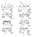
- FIGS. 1 to 7 have an essentially U-shaped cross section, which is formed from a base region 4 and side regions 5.
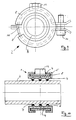
- the free ends of the side areas 5 are bent inwards, so that it is possible to encompass a rectangular cross section of a leg 8 (see FIG. 10) of a pipe clamp 2.
- FIG. 8 shows a straight leg 5.
- the side regions 5 are each made of a material of greater hardness, the corresponding harder regions are shown hatched in FIGS. 1 to 8.
- the exemplary embodiments furthermore have a plurality of knobs or ribs 6 on the base region 4, ie on the region which can be placed against a tube 3, which extend in a uniform arrangement over the length of the insert 1.
- 1, 2 and 4 to 8 each show different configurations of the nop pen or ribs 6.
- the embodiment shown in Fig. 3 has an essentially smooth surface of the base region 4, but this is provided with recesses 9, so that in this embodiment, the base region is provided with different thicknesses across the width.
- a surface layer 7 is provided on the surface of the base region, which either extends only on the knobs / ribs or is formed over the entire surface in the exemplary embodiment shown in FIG. 3.
- the surface layer 7 can be provided, for example, from a material with favorable sliding properties in order to reduce the frictional resistance to the pipe 3. It is also possible to design the surface layer 7 from a material of greater hardness, similar to the material of the side regions 5, so that the wear during relative movements between the insert and the tube can be reduced.
- the exemplary embodiments shown are each designed in their base region 4 in such a way that different material thicknesses exist across the width of the base region. These different material thicknesses lead to different clamping effects when the pipe clamp is tightened, so that a targeted application of force to the surface of the pipe 3 is possible.
- the pipe clamp 2 has two legs 8 which are movably anchored to one another at a hinge area.
- the free ends of the legs 8 are ge by means of a screw 11 biased against each other in order to press the insert 1 against the tube 3 in this way.
- the insert 1 can either be made in one piece, but it is also possible to dimension the length of the insert 1 so that it essentially corresponds to the inner peripheral region of the respective leg 8.
- the legs 8 have an essentially rectangular cross section, which is encompassed by the side regions 5 of the U-shaped cross section of the insert 1.
- the upper leg 8 shown in FIGS. 9 and 10 is connected to a nut 12 which can be used to suspend or mount the pipe clamp 2.
- FIG. 8 which represents the embodiment of the insert shown in FIG. 7 in the installed state, only the surface layers 7 of the knobs or ribs 6 are in contact with the surface of the tube 3,
Landscapes
- Engineering & Computer Science (AREA)
- General Engineering & Computer Science (AREA)
- Mechanical Engineering (AREA)
- Supports For Pipes And Cables (AREA)
- Clamps And Clips (AREA)
- Mutual Connection Of Rods And Tubes (AREA)
- External Artificial Organs (AREA)
- Branch Pipes, Bends, And The Like (AREA)
- Protection Of Pipes Against Damage, Friction, And Corrosion (AREA)
Abstract
Description
- Die Erfindung bezieht sich auf eine Einlage für eine Rohrschelle mit einer zentrischen, von zwei gegeneinander bewegbaren Schenkeln gebildeten Ausnehmung sowie auf eine Rohrschelle zur Verwendung der Einlage.
- Bei der Lagerung von Rohren hat es sich gezeigt, daß die üblicherweise verwendeten Strangpreßprofile, aus welchen die Einlagen geschnitten und in die Rohrschellen eingesetzt werden, nicht alle Anforderungen abdecken, da die verwendeten Materialien entweder keine ausreichende Geräuschdämmung ermöglichen oder bei zufriedenstellenden Dämmeigenschaften so weich sind, daß sie bei einer Relativbewegung zwischen dem Rohr und der Schelle von der Schelle gezogen werden und abfallen. Da üblicherweise sowohl bei der Montage eines Rohres als auch während dessen Benutzungen axiale Relativbewegungen zwischen der Schelle und dem Rohr auftreten, beispielsweise durch von dem Bedienungspersonal hervorgerufene Verschiebungen des Rohres oder durch thermische Ausdehnungen des Rohres, ist es wichtig, sicherzustel len, daß die üblicherweise aus einem Gummimaterial bestehende Einlage in korrektem Sitz an der Rohrschelle verbleibt.
- Der Erfindung liegt die Aufgabe zugrunde, eine Einlage der eingangs genannten Art zu schaffen, welche bei einfachem Aufbau und einfacher Herstellbarkeit sowohl eine ausreichende mechanische Festigkeit als auch eine gute Geräuschdämmung aufweist.
- Erfindungsgemäß wird die Aufgabe dadurch gelöst, die dem Rohr zugewandte Seite der Einlage mit einer Oberflächenschicht mit guten Gleiteigenschaften versehen ist.
- Vorteilhaft ist weiter, daß die Einlage an ihrem Verankerungsbereich aus einem härteren Material gefertigt ist, als an dem einem Rohr zugewandten Bereich.
- Die erfindungsgemäße Einlage zeichnet sich durch eine Reihe erheblicher Vorteile aus.
- Da der Lagerbereich der Einlage aus einem härteren und damit gleitfähigeren Material gefertigt ist, besteht nicht die Gefahr, daß die Einlage von der Rohrschelle abgezogen wird, wenn das Rohr in Längsrichtung relativ zu der Rohrschelle verschoben wird. Die Einlage hält vielmehr in sicherer Weise an der Rohrschelle und ist deshalb auch für Anwendungszwecke besonders gut geeignet, bei welchen das Rohr Schwingungen, insbesondere in seiner Längsrichtung, ausgesetzt ist.
- Die dem Rohr zugewandte Seite der Einlage ist somit erfindungsgemäß mit einer Oberflächenschicht mit guten Gleiteigenschaften versehen ist. Die Oberflächenschicht verhindert somit eine zu starke Reibung und damit eine übermäßige Verformung des Materials der Einlage bei einer Längsverschiebung des Rohres, so daß die Gefahr, daß die Einlage von der Schelle abgezogen wird, erheblich verringert werden kann. Weiterhin können Beschädigungen der Einlage vermieden werden, welche beispielsweise durch häufige Längsverschiebungen des Rohres, z.B. infolge von Temperaturwechselbeanspruchungen auftreten können.
- Erfindungsgemäß ist es weiterhin möglich, an dem der Rohrschelle zugewandten Bereich der Einlage ein wesentlich weicheres Material vorzusehen, welches bessere Geräuschdämpfungseigenschaften aufweist. Es ist somit möglich, jeweils eine optimale Materialauswahl zu treffen, einerseits hinsichtlich der Geräuschdämpfung und andererseits hinsichtlich der zur Verankerung erforderlichen Festigkeit.
- Weiterhin ist es vorteilhaft, daß die Einlage mit einem im wesentlichen U-förmigen Querschnitt versehen ist, dessen Basisbereich dem Rohr zugewandt ist und dessen Seitenbereiche zur Umgreifung der Rohrschelle nach innen umgebogen sind. Diese Form des Querschnitts gestattet zum einen eine sichere Verankerung der Einlage an der Rohrschelle, zum anderen ist es möglich, den Basisbereich den jeweiligen Anforderungen gemäß auszugestalten, ohne daß hierdurch die Gesamtfestigkeit und/oder Befestigbarkeit der Rohrschelle beeinträchtigt wurde. So ist es beispielsweise insbesondere möglich, den Basisbereich mit Noppen oder Rippen zu versehen, um gezielte Anlageflächen zu dem Rohr zu schaffen. Diese können beispielsweise auch hinsichtlich der thermischen Isolierung vorteilhaft sein, da bei höheren Temperaturen des Rohres nicht die gesamte Fläche der Einlage mit dem Rohr in Berührung kommt. Beschädigungen der Einlage durch höhere Temperaturen können somit vielfach vermieden werden.
- Erfindungsgemäß ist es durch die Möglichkeit, verschiedene Materialien miteinander zu paaren auch möglich, die Noppen oder Rippen oder lediglich den Basisbereich mit einer Oberflächenschicht zu versehen, welche aus einem härteren Material gefertigt ist. Zusätzlich oder alternativ zu der Gleiteigenschaft der Oberflächenschicht kann somit der Verschleißwiderstand erhöht werden, es ist auch möglich, die guten Gleiteigenschaften mit der größeren Oberflächenhärte zu kombinieren oder alternativ vorzusehen.
- In einer weiteren vorteilhaften Ausgestaltung der Erfindung weist die Einlage an ihrem Basisbereich über die Breite Zonen unterschiedlicher Dicke auf. Diese Zonen gestatten es, die Einlage beim Andrücken gegen das Rohr in unterschiedlicher Weise zu verformen, um auf diese Weise definierte Stütz- oder Haltekräfte aufbringen zu können.
- Die erfindungsgemäße Einlage gestattet somit einen festen Sitz auf der Rohrschelle und verhindert ein Herausspringen bei axialen Bewegungen des Rohres. Weiterhin ermöglicht das weichere Material im Basisbereich der Einlage eine Schalldämmung gemäß DIN 4109, welche über lange Zeiträume gewährleistet sein kann, da keine mechanischen Beeinträchtigungen der Einlage zu befürchten sind.
- Im folgenden wird die Erfindung anhand von Ausführungsbeispielen in Verbindung mit der Zeichnung beschrieben. Dabei zeigt:
- Fig. 1 bis 8 verschiedene Querschnittsvarianten der erfindungsgemäßen Einlage,
- Fig. 9 eine Seitenansicht einer erfindungsgemäßen Rohrschelle mit eingesetzter Einlage und
- Fig. 10 eine Schnittansicht durch die in Fig. 9 dargestellte Rohrschelle.
- Die in den Fig. 1 bis 7 gezeigten Ausführungsbeispiele einer erfindungsgemäßen Einlage 1 weisen einen im wesentlichen U-förmigen Querschnitt auf, welcher aus einem Basisbereich 4 und Seitenbereichen 5 gebildet wird. Die freien Enden der Seitenbereiche 5 sind nach innen umgebogen, so daß es möglich ist, einen rechteckförmigen Querschnitt eines Schenkels 8 (siehe Fig. 10) einer Rohrschelle 2 zu umgreifen. Die Figur 8 zeigt einen geraden Schenkel 5.
- Bei den gezeigten Ausführungsbeispielen sind die Seitenbereiche 5 jeweils aus einem Material größerer Härte gefertigt, die entsprechenden härteren Bereiche sind in den Fig. 1 bis 8 schraffiert dargestellt.
- Die Ausführungsbeispiele weisen weiterhin an dem Basisbereich 4, d.h. an dem Bereich, welcher gegen ein Rohr 3 anlegbar ist, mehrere Noppen oder Rippen 6 auf, welche sich in gleichmäßiger Anordnung über die Länge der Einlage 1 erstrecken. Die Fig. 1, 2 und 4 bis 8 zeigen jeweils unterschiedliche Ausgestaltungsformen der Nop pen oder Rippen 6. Das in Fig. 3 gezeigte Ausführungsbeispiel weist eine im wesentlichen glatte Oberfläche des Basisbereiches 4 auf, dieser ist jedoch mit Ausnehmungen 9 versehen, so daß auch bei diesem Ausführungsbeispiel der Basisbereich über die Breite mit unterschiedlichen Dicken versehen ist.
- Bei den gezeigten Aüsfuhrungsbeispielen ist an der Oberfläche des Basisbereichs jeweils eine Oberflächenschicht 7 vorgesehen, welche sich entweder nur an den Noppen/Rippen erstreckt oder bei dem in Fig. 3 gezeigten Ausführungsbeispiel über die gesamte Fläche ausgebildet ist. Die Oberflächenschicht 7 kann beispielsweise aus einem Material mit günstigen Gleiteigenschaften versehen sein, um den Reibungswiderstand zu dem Rohr 3 zu verringern. Es ist auch möglich, die Oberflächenschicht 7 aus einem Material größerer Härte, ähnlich dem Material der Seitenbereiche 5 auszugestalten, so daß der Verschleiß bei Relativbewegungen zwischen der Einlage und dem Rohr vermindert werden kann.
- Die gezeigten Ausführungsbeispiele sind in ihrem Basisbereich 4 jeweils so ausgebildet, daß über die Breite des Basisbereichs unterschiedliche Materialdicken vorliegen. Diese unterschiedlichen Materialdicken führen bei einem Anziehen der Rohrschelle zu unterschiedlichen Klemmwirkungen, so daß eine gezielte Kraftaufbringung auf die Oberfläche des Rohres 3 möglich ist.
- Die Fig. 9 und 10 zeigen jeweils eine Ansicht der erfindungsgemäßen Einlage 1 im eingebauten Zustand in Verbindung mit einer Rohrschelle 2. Die Rohrschelle 2 weist zwei Schenkel 8 auf, welche an einem Scharnierbereich beweglich miteinander verankert sind. Die freien Enden der Schenkel 8 sind mittels einer Schraube 11 ge geneinander vorspannbar, um auf diese Weise die Einlage 1 gegen das Rohr 3 zu drücken. Die Einlage 1 kann entweder einstückig ausgebildet sein, es ist jedoch auch möglich, die Länge der Einlage 1 so zu bemessen, daß diese im wesentlichen dem inneren Umfangsbereich des jeweiligen Schenkels 8 entspricht.
- Wie aus Fig. 10 ersichtlich ist, weisen die Schenkel 8 einen im wesentlichen rechteckförmigen Querschnitt auf, welcher von den Seitenbereichen 5 des U-förmigen Querschnitts der Einlage 1 umgriffen wird.
- Der in den Fig. 9 und 10 gezeigte obere Schenkel 8 ist mit einer Mutter 12 verbunden, welche zur Aufhängung oder Montage der Rohrschelle 2 dienen kann.
- Wie aus Fig. 8 ersichtlich ist, welche das in Fig. 7 gezeigte Ausführungsbeispiel der Einlage im eingebauten Zustand darstellt, befinden sich lediglich die Oberflächenschichten 7 der Noppen oder Rippen 6 in Kontakt mit der Oberfläche des Rohres 3,
- Die Erfindung ist nicht auf das gezeigte Ausführungsbeispiel beschränkt, vielmehr ergeben sich für den Fachmann im Rahmen der Erfindung vielfältige Abwandlungs- und Modifikationsmöglichkeiten.
Claims (11)
Priority Applications (1)
| Application Number | Priority Date | Filing Date | Title |
|---|---|---|---|
| AT90100063T ATE92600T1 (de) | 1989-08-25 | 1990-01-03 | Einlage fuer eine rohrschelle. |
Applications Claiming Priority (2)
| Application Number | Priority Date | Filing Date | Title |
|---|---|---|---|
| DE8910177U DE8910177U1 (de) | 1989-08-25 | 1989-08-25 | Einlage für eine Rohrschelle |
| DE8910177U | 1989-08-25 |
Publications (2)
| Publication Number | Publication Date |
|---|---|
| EP0413883A1 true EP0413883A1 (de) | 1991-02-27 |
| EP0413883B1 EP0413883B1 (de) | 1993-08-04 |
Family
ID=6842292
Family Applications (1)
| Application Number | Title | Priority Date | Filing Date |
|---|---|---|---|
| EP90100063A Expired - Lifetime EP0413883B1 (de) | 1989-08-25 | 1990-01-03 | Einlage für eine Rohrschelle |
Country Status (5)
| Country | Link |
|---|---|
| EP (1) | EP0413883B1 (de) |
| AT (1) | ATE92600T1 (de) |
| DE (2) | DE8910177U1 (de) |
| DK (1) | DK0413883T3 (de) |
| ES (1) | ES2045566T3 (de) |
Cited By (20)
| Publication number | Priority date | Publication date | Assignee | Title |
|---|---|---|---|---|
| DE4213893A1 (de) * | 1992-04-28 | 1993-11-04 | Sikla Gmbh & Co Kg | Rohrschelle |
| EP0582354A1 (de) * | 1992-08-05 | 1994-02-09 | J. van Walraven B.V. | Verfahren zur Befestigung eines Rohres in vertikaler Lage an einer Wand |
| EP0585543A1 (de) * | 1992-08-31 | 1994-03-09 | E. Missel GmbH & Co. | Rohrbefestigungsvorrichtung mit einer Fixier- und einer Stützschelle |
| NL9300521A (nl) * | 1993-03-23 | 1994-10-17 | Walraven J Van Bv | Werkwijze voor het in een vertikale positie bevestigen van een leiding aan een wand. |
| US5384936A (en) * | 1991-05-08 | 1995-01-31 | J. Van Walraven B.V. | Pipe-clip |
| EP0639739A1 (de) * | 1993-08-21 | 1995-02-22 | HILTI Aktiengesellschaft | Rohrschelle mit elastischer Einlage |
| US5647564A (en) * | 1992-08-05 | 1997-07-15 | J. Van Walraven B.V. | Method for fastening a pipe in a vertical position to a wall |
| EP0809060A3 (de) * | 1996-05-24 | 1998-04-15 | Diag Design Ag | Gelenkverbindung für Rohrschelle |
| DE10014050C1 (de) * | 2000-03-23 | 2001-10-31 | Rehau Ag & Co | Vorrichtung zur Befestigung von Rohren |
| NL1021220C2 (nl) | 2002-08-06 | 2004-02-10 | Walraven J Van Bv | Trillingisolerende pijpbeugel. |
| EP1770323A3 (de) * | 2005-09-29 | 2007-04-25 | Semperit Aktiengesellschaft Holding | Einlage für eine Rohrschelle |
| DE102007052701A1 (de) * | 2007-11-06 | 2009-05-07 | Fischerwerke Gmbh & Co. Kg | Elastische Einlage für eine Rohrschelle |
| EP2072874A1 (de) | 2007-12-21 | 2009-06-24 | HILTI Aktiengesellschaft | Rohrschelle |
| DE102008036386B4 (de) * | 2008-08-05 | 2012-03-15 | Sina Befestigungssysteme Gmbh | Rohrschelle und Profilelement für eine Rohrschelle |
| DE202012103440U1 (de) | 2012-09-10 | 2012-09-28 | Edgar Emil Sinn | Rohrschelle und Einlage für eine Rohrschelle |
| DE202013101185U1 (de) | 2012-03-20 | 2013-04-10 | J. Van Walraven Holding B.V. | Schwingungsdämpfende Einlage |
| WO2015002339A1 (ko) * | 2013-07-02 | 2015-01-08 | 엠티코리아(주) | 파이프 클램프 |
| EP2734767A4 (de) * | 2011-07-21 | 2015-01-14 | Ideal Clamp Products Inc | Schlauchklemme mit einer gerippten federhülse |
| EP2860437A1 (de) | 2013-10-14 | 2015-04-15 | J. van Walraven Holding B.V. | Einlage für Rohrklemmen |
| WO2016056895A3 (en) * | 2014-10-08 | 2016-06-02 | J. Van Walraven Holding B.V. | Vibration isolating insert for a pipe clip and method for manufacturing such an insert. |
Families Citing this family (4)
| Publication number | Priority date | Publication date | Assignee | Title |
|---|---|---|---|---|
| DE102007052559A1 (de) * | 2007-11-03 | 2009-05-07 | Fischerwerke Gmbh & Co. Kg | Elastische Einlage für eine Rohrschelle |
| DE102020118792B4 (de) | 2020-07-16 | 2023-06-07 | Ford Global Technologies Llc | Verbindungsanordnung für einen Fahrzeugsitz |
| CN116486771B (zh) * | 2022-01-13 | 2025-10-28 | 喜利得股份公司 | 用于安装支架的隔音插件 |
| DE202022101477U1 (de) | 2022-03-22 | 2023-06-23 | REHAU Industries SE & Co. KG | Schalldämmeinlage aus einem Dämmmaterial für eine Rohrschelle und Rohrschelle, die eine derartige Schalldämmeinlage umfasst |
Citations (5)
| Publication number | Priority date | Publication date | Assignee | Title |
|---|---|---|---|---|
| GB592755A (en) * | 1943-09-14 | 1947-09-29 | Adel Prec Products Corp | Cushion for conduit and wire supporting clips |
| US4189807A (en) * | 1976-11-15 | 1980-02-26 | Viking Industries, Inc. | Clamp |
| US4441677A (en) * | 1982-04-02 | 1984-04-10 | Ta Mfg., Inc. | Clamp device |
| EP0148768A2 (de) * | 1984-01-06 | 1985-07-17 | Webco Industrial Rubber Limited | Klemme |
| FR2640349A1 (fr) * | 1988-12-09 | 1990-06-15 | Hb Tech Sa | Collier de fixation de tuyauteries |
-
1989
- 1989-08-25 DE DE8910177U patent/DE8910177U1/de not_active Expired - Lifetime
-
1990
- 1990-01-03 DE DE9090100063T patent/DE59002173D1/de not_active Expired - Fee Related
- 1990-01-03 ES ES90100063T patent/ES2045566T3/es not_active Expired - Lifetime
- 1990-01-03 DK DK90100063.8T patent/DK0413883T3/da active
- 1990-01-03 EP EP90100063A patent/EP0413883B1/de not_active Expired - Lifetime
- 1990-01-03 AT AT90100063T patent/ATE92600T1/de not_active IP Right Cessation
Patent Citations (5)
| Publication number | Priority date | Publication date | Assignee | Title |
|---|---|---|---|---|
| GB592755A (en) * | 1943-09-14 | 1947-09-29 | Adel Prec Products Corp | Cushion for conduit and wire supporting clips |
| US4189807A (en) * | 1976-11-15 | 1980-02-26 | Viking Industries, Inc. | Clamp |
| US4441677A (en) * | 1982-04-02 | 1984-04-10 | Ta Mfg., Inc. | Clamp device |
| EP0148768A2 (de) * | 1984-01-06 | 1985-07-17 | Webco Industrial Rubber Limited | Klemme |
| FR2640349A1 (fr) * | 1988-12-09 | 1990-06-15 | Hb Tech Sa | Collier de fixation de tuyauteries |
Cited By (29)
| Publication number | Priority date | Publication date | Assignee | Title |
|---|---|---|---|---|
| US5384936A (en) * | 1991-05-08 | 1995-01-31 | J. Van Walraven B.V. | Pipe-clip |
| DE4213893A1 (de) * | 1992-04-28 | 1993-11-04 | Sikla Gmbh & Co Kg | Rohrschelle |
| US5647564A (en) * | 1992-08-05 | 1997-07-15 | J. Van Walraven B.V. | Method for fastening a pipe in a vertical position to a wall |
| EP0582354A1 (de) * | 1992-08-05 | 1994-02-09 | J. van Walraven B.V. | Verfahren zur Befestigung eines Rohres in vertikaler Lage an einer Wand |
| WO1994003750A1 (en) * | 1992-08-05 | 1994-02-17 | J. Van Walraven B.V. | A method for fastening a pipe in a vertical position to a wall |
| EP0585543A1 (de) * | 1992-08-31 | 1994-03-09 | E. Missel GmbH & Co. | Rohrbefestigungsvorrichtung mit einer Fixier- und einer Stützschelle |
| NL9300521A (nl) * | 1993-03-23 | 1994-10-17 | Walraven J Van Bv | Werkwijze voor het in een vertikale positie bevestigen van een leiding aan een wand. |
| EP0639739A1 (de) * | 1993-08-21 | 1995-02-22 | HILTI Aktiengesellschaft | Rohrschelle mit elastischer Einlage |
| EP0809060A3 (de) * | 1996-05-24 | 1998-04-15 | Diag Design Ag | Gelenkverbindung für Rohrschelle |
| DE10014050C1 (de) * | 2000-03-23 | 2001-10-31 | Rehau Ag & Co | Vorrichtung zur Befestigung von Rohren |
| NL1021220C2 (nl) | 2002-08-06 | 2004-02-10 | Walraven J Van Bv | Trillingisolerende pijpbeugel. |
| WO2004013534A1 (en) | 2002-08-06 | 2004-02-12 | J. Van Walraven B.V. | Vibration isolating pipe clip |
| US7611101B2 (en) | 2002-08-06 | 2009-11-03 | J. Van Walraven B.V. | Vibration isolating pipe clip |
| EP1770323A3 (de) * | 2005-09-29 | 2007-04-25 | Semperit Aktiengesellschaft Holding | Einlage für eine Rohrschelle |
| DE102007052701A1 (de) * | 2007-11-06 | 2009-05-07 | Fischerwerke Gmbh & Co. Kg | Elastische Einlage für eine Rohrschelle |
| EP2072874A1 (de) | 2007-12-21 | 2009-06-24 | HILTI Aktiengesellschaft | Rohrschelle |
| DE202007018953U1 (de) | 2007-12-21 | 2009-12-10 | Hilti Aktiengesellschaft | Rohrschelle |
| DE102007055906A1 (de) | 2007-12-21 | 2009-06-25 | Hilti Aktiengesellschaft | Rohrschelle |
| DE102008036386B4 (de) * | 2008-08-05 | 2012-03-15 | Sina Befestigungssysteme Gmbh | Rohrschelle und Profilelement für eine Rohrschelle |
| EP2734767A4 (de) * | 2011-07-21 | 2015-01-14 | Ideal Clamp Products Inc | Schlauchklemme mit einer gerippten federhülse |
| DE202013101185U1 (de) | 2012-03-20 | 2013-04-10 | J. Van Walraven Holding B.V. | Schwingungsdämpfende Einlage |
| DE202012103440U1 (de) | 2012-09-10 | 2012-09-28 | Edgar Emil Sinn | Rohrschelle und Einlage für eine Rohrschelle |
| WO2015002339A1 (ko) * | 2013-07-02 | 2015-01-08 | 엠티코리아(주) | 파이프 클램프 |
| EP2860437A1 (de) | 2013-10-14 | 2015-04-15 | J. van Walraven Holding B.V. | Einlage für Rohrklemmen |
| WO2016056895A3 (en) * | 2014-10-08 | 2016-06-02 | J. Van Walraven Holding B.V. | Vibration isolating insert for a pipe clip and method for manufacturing such an insert. |
| NL2013596B1 (en) * | 2014-10-08 | 2016-10-04 | Walraven Holding Bv J Van | Vibration isolating insert for a pipe clip and method for manufacturing such an insert. |
| CN106794613A (zh) * | 2014-10-08 | 2017-05-31 | J·范瓦尔拉芬私人控股有限公司 | 管夹的隔震插入件和制造这种插入件的方法 |
| US10317002B2 (en) | 2014-10-08 | 2019-06-11 | J. Van Walraven Holding B.V. | Vibration isolating insert for a pipe clip and method for manufacturing such an insert |
| CN106794613B (zh) * | 2014-10-08 | 2019-08-16 | J·范瓦尔拉芬私人控股有限公司 | 管夹的隔震插入件和制造这种插入件的方法 |
Also Published As
| Publication number | Publication date |
|---|---|
| ES2045566T3 (es) | 1994-01-16 |
| EP0413883B1 (de) | 1993-08-04 |
| DE59002173D1 (de) | 1993-09-09 |
| ATE92600T1 (de) | 1993-08-15 |
| DE8910177U1 (de) | 1989-12-28 |
| DK0413883T3 (da) | 1993-12-13 |
Similar Documents
| Publication | Publication Date | Title |
|---|---|---|
| EP0413883B1 (de) | Einlage für eine Rohrschelle | |
| DE2304676C2 (de) | Dichtungsring aus elastomerem Material | |
| DE69503256T2 (de) | Verstellbare lenksäule | |
| DE69217871T2 (de) | Wälzlager für Linearbewegungen | |
| EP0750721A1 (de) | Verbindungselement | |
| EP2150743B1 (de) | Klemmfitting fuer ein rohr | |
| DE2758463B2 (de) | Endoskop mit flexiblem Endabschnitt und Krümmungseinrichtung dafür | |
| DE6938649U (de) | Vorrichtung zur schwingungs- und geraeuschdaempfung in scheibenbremsen | |
| DE3523592A1 (de) | Buegelhalterung fuer ohrschuetzer | |
| DE10217333B4 (de) | Flachmutteraufbau | |
| EP1909011A2 (de) | Rohrschelle | |
| EP0790420B1 (de) | Gleitblock für eine Teleskopsäule | |
| EP0884518B1 (de) | Einlage für eine Rohrschelle | |
| WO2015010893A1 (de) | Chirurgischer clip, insbesondere aneurysmenclip | |
| DE3741487A1 (de) | Zwischen zwei knochen einsetzbares stuetzelement | |
| DE202007007827U1 (de) | Klemmfitting für ein Rohr | |
| DE102006043206A1 (de) | Schiebeblende/Rast-Feder-Käfig | |
| DE9207276U1 (de) | Kompensationselement für Kunststoffmantelrohrleitungen | |
| DE3907067A1 (de) | Rohrhalterung | |
| DE2238639C3 (de) | Elektrische Steckfassung für Schaltungskalten | |
| DE3341432C2 (de) | Spielgerät | |
| DE20220736U1 (de) | Spannzange und Distanzelement für Spannzangen | |
| DE4022313A1 (de) | Moebelteil mit einem elastischen griffelement | |
| DE1256603B (de) | Wischer zum Reinigen von Rohren od. dgl. | |
| DE102020204893A1 (de) | Gleitvorrichtung und eine die gleitvorrichtung umfassende armlehne |
Legal Events
| Date | Code | Title | Description |
|---|---|---|---|
| PUAI | Public reference made under article 153(3) epc to a published international application that has entered the european phase |
Free format text: ORIGINAL CODE: 0009012 |
|
| AK | Designated contracting states |
Kind code of ref document: A1 Designated state(s): AT BE CH DE DK ES FR GB GR IT LI LU NL SE |
|
| 17P | Request for examination filed |
Effective date: 19910603 |
|
| 17Q | First examination report despatched |
Effective date: 19911210 |
|
| GRAA | (expected) grant |
Free format text: ORIGINAL CODE: 0009210 |
|
| AK | Designated contracting states |
Kind code of ref document: B1 Designated state(s): AT BE CH DE DK ES FR GB GR IT LI LU NL SE |
|
| PG25 | Lapsed in a contracting state [announced via postgrant information from national office to epo] |
Ref country code: GR Free format text: LAPSE BECAUSE OF FAILURE TO SUBMIT A TRANSLATION OF THE DESCRIPTION OR TO PAY THE FEE WITHIN THE PRESCRIBED TIME-LIMIT Effective date: 19930804 |
|
| REF | Corresponds to: |
Ref document number: 92600 Country of ref document: AT Date of ref document: 19930815 Kind code of ref document: T |
|
| ITF | It: translation for a ep patent filed | ||
| REF | Corresponds to: |
Ref document number: 59002173 Country of ref document: DE Date of ref document: 19930909 |
|
| REG | Reference to a national code |
Ref country code: GR Ref legal event code: FG4A Free format text: 3008678 |
|
| ET | Fr: translation filed | ||
| REG | Reference to a national code |
Ref country code: DK Ref legal event code: T3 |
|
| GBT | Gb: translation of ep patent filed (gb section 77(6)(a)/1977) |
Effective date: 19931112 |
|
| REG | Reference to a national code |
Ref country code: ES Ref legal event code: FG2A Ref document number: 2045566 Country of ref document: ES Kind code of ref document: T3 |
|
| EPTA | Lu: last paid annual fee | ||
| PLBE | No opposition filed within time limit |
Free format text: ORIGINAL CODE: 0009261 |
|
| STAA | Information on the status of an ep patent application or granted ep patent |
Free format text: STATUS: NO OPPOSITION FILED WITHIN TIME LIMIT |
|
| 26N | No opposition filed | ||
| REG | Reference to a national code |
Ref country code: GR Ref legal event code: MM2A Free format text: 3008678 |
|
| EAL | Se: european patent in force in sweden |
Ref document number: 90100063.8 |
|
| PGFP | Annual fee paid to national office [announced via postgrant information from national office to epo] |
Ref country code: GB Payment date: 19971229 Year of fee payment: 9 |
|
| PGFP | Annual fee paid to national office [announced via postgrant information from national office to epo] |
Ref country code: SE Payment date: 19980102 Year of fee payment: 9 |
|
| PGFP | Annual fee paid to national office [announced via postgrant information from national office to epo] |
Ref country code: LU Payment date: 19980115 Year of fee payment: 9 |
|
| PGFP | Annual fee paid to national office [announced via postgrant information from national office to epo] |
Ref country code: DK Payment date: 19980127 Year of fee payment: 9 |
|
| PG25 | Lapsed in a contracting state [announced via postgrant information from national office to epo] |
Ref country code: LU Free format text: LAPSE BECAUSE OF NON-PAYMENT OF DUE FEES Effective date: 19990103 Ref country code: GB Free format text: LAPSE BECAUSE OF NON-PAYMENT OF DUE FEES Effective date: 19990103 |
|
| PG25 | Lapsed in a contracting state [announced via postgrant information from national office to epo] |
Ref country code: SE Free format text: LAPSE BECAUSE OF NON-PAYMENT OF DUE FEES Effective date: 19990104 |
|
| PG25 | Lapsed in a contracting state [announced via postgrant information from national office to epo] |
Ref country code: DK Free format text: LAPSE BECAUSE OF NON-PAYMENT OF DUE FEES Effective date: 19990202 |
|
| GBPC | Gb: european patent ceased through non-payment of renewal fee |
Effective date: 19990103 |
|
| REG | Reference to a national code |
Ref country code: CH Ref legal event code: PFA Free format text: POPPE + CO. GIESSENER GUMMIWARENFABRIK GMBH & CO. KG TRANSFER- POPPE GMBH & CO. KG |
|
| REG | Reference to a national code |
Ref country code: DK Ref legal event code: EBP |
|
| REG | Reference to a national code |
Ref country code: FR Ref legal event code: CD |
|
| NLT1 | Nl: modifications of names registered in virtue of documents presented to the patent office pursuant to art. 16 a, paragraph 1 |
Owner name: POPPE GMBH & CO. KG. |
|
| REG | Reference to a national code |
Ref country code: ES Ref legal event code: PC2A |
|
| PGFP | Annual fee paid to national office [announced via postgrant information from national office to epo] |
Ref country code: FR Payment date: 20021227 Year of fee payment: 14 |
|
| PGFP | Annual fee paid to national office [announced via postgrant information from national office to epo] |
Ref country code: BE Payment date: 20021231 Year of fee payment: 14 |
|
| PGFP | Annual fee paid to national office [announced via postgrant information from national office to epo] |
Ref country code: AT Payment date: 20030122 Year of fee payment: 14 |
|
| PGFP | Annual fee paid to national office [announced via postgrant information from national office to epo] |
Ref country code: CH Payment date: 20030128 Year of fee payment: 14 |
|
| PGFP | Annual fee paid to national office [announced via postgrant information from national office to epo] |
Ref country code: NL Payment date: 20030131 Year of fee payment: 14 |
|
| PGFP | Annual fee paid to national office [announced via postgrant information from national office to epo] |
Ref country code: ES Payment date: 20030227 Year of fee payment: 14 |
|
| PGFP | Annual fee paid to national office [announced via postgrant information from national office to epo] |
Ref country code: DE Payment date: 20030312 Year of fee payment: 14 |
|
| PG25 | Lapsed in a contracting state [announced via postgrant information from national office to epo] |
Ref country code: AT Free format text: LAPSE BECAUSE OF NON-PAYMENT OF DUE FEES Effective date: 20040103 |
|
| PG25 | Lapsed in a contracting state [announced via postgrant information from national office to epo] |
Ref country code: ES Free format text: LAPSE BECAUSE OF NON-PAYMENT OF DUE FEES Effective date: 20040105 |
|
| PG25 | Lapsed in a contracting state [announced via postgrant information from national office to epo] |
Ref country code: LI Free format text: LAPSE BECAUSE OF NON-PAYMENT OF DUE FEES Effective date: 20040131 Ref country code: CH Free format text: LAPSE BECAUSE OF NON-PAYMENT OF DUE FEES Effective date: 20040131 Ref country code: BE Free format text: LAPSE BECAUSE OF NON-PAYMENT OF DUE FEES Effective date: 20040131 |
|
| BERE | Be: lapsed |
Owner name: *POPPE G.M.B.H. & CO. K.G. Effective date: 20040131 |
|
| PG25 | Lapsed in a contracting state [announced via postgrant information from national office to epo] |
Ref country code: NL Free format text: LAPSE BECAUSE OF NON-PAYMENT OF DUE FEES Effective date: 20040801 |
|
| PG25 | Lapsed in a contracting state [announced via postgrant information from national office to epo] |
Ref country code: DE Free format text: LAPSE BECAUSE OF NON-PAYMENT OF DUE FEES Effective date: 20040803 |
|
| REG | Reference to a national code |
Ref country code: CH Ref legal event code: PL |
|
| PG25 | Lapsed in a contracting state [announced via postgrant information from national office to epo] |
Ref country code: FR Free format text: LAPSE BECAUSE OF NON-PAYMENT OF DUE FEES Effective date: 20040930 |
|
| NLV4 | Nl: lapsed or anulled due to non-payment of the annual fee |
Effective date: 20040801 |
|
| REG | Reference to a national code |
Ref country code: FR Ref legal event code: ST |
|
| PG25 | Lapsed in a contracting state [announced via postgrant information from national office to epo] |
Ref country code: IT Free format text: LAPSE BECAUSE OF NON-PAYMENT OF DUE FEES;WARNING: LAPSES OF ITALIAN PATENTS WITH EFFECTIVE DATE BEFORE 2007 MAY HAVE OCCURRED AT ANY TIME BEFORE 2007. THE CORRECT EFFECTIVE DATE MAY BE DIFFERENT FROM THE ONE RECORDED. Effective date: 20050103 |
|
| REG | Reference to a national code |
Ref country code: ES Ref legal event code: FD2A Effective date: 20040105 |