EP0415380A1 - Procédé et dispositif pour la préparation des corps de plantes contenant des fibres - Google Patents
Procédé et dispositif pour la préparation des corps de plantes contenant des fibres Download PDFInfo
- Publication number
- EP0415380A1 EP0415380A1 EP90116533A EP90116533A EP0415380A1 EP 0415380 A1 EP0415380 A1 EP 0415380A1 EP 90116533 A EP90116533 A EP 90116533A EP 90116533 A EP90116533 A EP 90116533A EP 0415380 A1 EP0415380 A1 EP 0415380A1
- Authority
- EP
- European Patent Office
- Prior art keywords
- plant
- conveyor
- plant material
- impact
- bodies
- Prior art date
- Legal status (The legal status is an assumption and is not a legal conclusion. Google has not performed a legal analysis and makes no representation as to the accuracy of the status listed.)
- Granted
Links
- 238000000034 method Methods 0.000 title claims abstract description 23
- 239000000463 material Substances 0.000 claims abstract description 88
- 238000003825 pressing Methods 0.000 claims abstract description 27
- 238000001035 drying Methods 0.000 claims abstract description 18
- 241000196324 Embryophyta Species 0.000 claims description 164
- 239000000835 fiber Substances 0.000 claims description 15
- 230000002093 peripheral effect Effects 0.000 claims description 9
- 238000000151 deposition Methods 0.000 claims description 6
- 230000009471 action Effects 0.000 claims description 5
- 238000005520 cutting process Methods 0.000 claims description 4
- 230000000452 restraining effect Effects 0.000 claims description 4
- 244000198134 Agave sisalana Species 0.000 claims description 3
- 244000025254 Cannabis sativa Species 0.000 claims description 3
- 235000004431 Linum usitatissimum Nutrition 0.000 claims description 3
- 241000251131 Sphyrna Species 0.000 claims description 3
- 230000001419 dependent effect Effects 0.000 claims description 3
- 238000002360 preparation method Methods 0.000 claims description 3
- 230000000717 retained effect Effects 0.000 claims description 3
- 240000006240 Linum usitatissimum Species 0.000 claims 1
- 238000004132 cross linking Methods 0.000 claims 1
- 235000011389 fruit/vegetable juice Nutrition 0.000 claims 1
- 230000001105 regulatory effect Effects 0.000 claims 1
- 238000010009 beating Methods 0.000 abstract 2
- 230000000694 effects Effects 0.000 description 11
- 239000010902 straw Substances 0.000 description 8
- 230000029087 digestion Effects 0.000 description 5
- 241000208202 Linaceae Species 0.000 description 2
- 230000005540 biological transmission Effects 0.000 description 2
- 230000008878 coupling Effects 0.000 description 2
- 238000010168 coupling process Methods 0.000 description 2
- 238000005859 coupling reaction Methods 0.000 description 2
- 230000008569 process Effects 0.000 description 2
- 238000011144 upstream manufacturing Methods 0.000 description 2
- 206010013786 Dry skin Diseases 0.000 description 1
- 230000000903 blocking effect Effects 0.000 description 1
- 230000008859 change Effects 0.000 description 1
- 238000005056 compaction Methods 0.000 description 1
- 230000014759 maintenance of location Effects 0.000 description 1
- 238000004519 manufacturing process Methods 0.000 description 1
- 230000001404 mediated effect Effects 0.000 description 1
- 239000002184 metal Substances 0.000 description 1
- 230000008439 repair process Effects 0.000 description 1
- 239000002689 soil Substances 0.000 description 1
Images


Classifications
-
- A—HUMAN NECESSITIES
- A01—AGRICULTURE; FORESTRY; ANIMAL HUSBANDRY; HUNTING; TRAPPING; FISHING
- A01D—HARVESTING; MOWING
- A01D45/00—Harvesting of standing crops
- A01D45/06—Harvesting of standing crops of flax or similar fibrous plants
-
- A—HUMAN NECESSITIES
- A01—AGRICULTURE; FORESTRY; ANIMAL HUSBANDRY; HUNTING; TRAPPING; FISHING
- A01D—HARVESTING; MOWING
- A01D43/00—Mowers combined with apparatus performing additional operations while mowing
- A01D43/10—Mowers combined with apparatus performing additional operations while mowing with means for crushing or bruising the mown crop
Definitions
- the invention relates to a working method for processing fibrous plant bodies (grass, flax, sisal and the like), in which the plant bodies are separated from their root balls in the field and disrupted before drying.
- the invention further relates to a device for carrying out the above-mentioned method with a feed device for introducing the plant material separated from its root ball into an area for opening the plant bodies, a device for opening the plant material and optionally a device for depositing the open plant bodies in the field.
- the invention is therefore based on the object of specifying a method in which the disadvantages of the method described are not to be feared and which is suitable for the simple and effective use of plant bodies of different types, such as grass, flax, sisal or other palm Prepare fibers to dry the initial moisture content in the field as quickly as possible and to be able to bring the plant material under cover within a short time. Furthermore, a device is to be created which is suitable for carrying out the method and which is constructed in such a simple manner that it can also be purchased by smaller companies.
- the plant carpet is continuously torn open and the stalks contained in it are opened. This is particularly important if several areas are used in series to unlock the plant material. If the working speed of the respective subsequent area is preferably chosen to be greater than that of the previous area, then it results that the working speed is greatest at the end of the working process. To accelerate the drying process, the digested straws are either laid down loosely on the field or a compacted mat is formed from the digested straws before it is placed on the field.
- the plant bodies In order to achieve an optimal preparation of the plant material, one must avoid that the plant bodies are cut up while they pass through the device. Rather, the individual plant bodies should be torn open in their longitudinal direction.
- this effect is achieved in that the plant bodies, which are initially flatly combined, are fed at slow speed to the impact-pull-tear-press tool, the working and conveying speed of which is chosen to be considerably higher. This ensures that the combined plant bodies are continuously torn open and individual stalks are opened. As a result of the lower feeding speed of the planarly combined plant bodies, these are constantly held back somewhat compared to the higher working speed of the impact-pull-tear and pressing tool.
- the degree of digestion that can be achieved is crucially determined by the difference between the speeds of the plant material in the conveying channel and the peripheral speed of the impact-pull-tear and pressing tool.
- the dimensions of the conveying channel can preferably be selected as a function of the tension exerted by the impact-pull-tear and pressing tool in such a way that a retention force is exerted on the plant material in the channel which is sufficient to prevent the impact caused by the impact-pull-tear and pressing tool on the plant material counteracting pull to hold it back.
- the channel width can be changed by changing the bearing setting of the conveyor roller and guide wall can be changed.
- the achievable degree of disintegration of the plant bodies can also be influenced by the choice of the length of the face.
- the length of the striking surface viewed in the conveying direction, can preferably be selected in accordance with the ratio between the conveying speed of the plant material fed to it and the circumferential speed of the striking, pulling and pressing tool.
- the disintegrated plant material can either be placed loosely on the field after leaving the area or areas for disintegrating the plant bodies, but a device for depositing the disintegrated plant material can optionally be used.
- This preferably comprises at least two counter-rotating rollers, which take over the compacted plant material, compact it and eject it in the form of a mat, which is either deposited on the field or taken over by a further conveying device.
- the plant material supplied to the device can be aligned as uniformly as possible in the conveying or working direction before it is separated from its root ball.
- this requirement requires that the activities of the separating device and the device for entering the plant material are functionally coordinated with one another, the separating or cutting edge of the separating device having to be connected downstream of the input device in accordance with the length of the plant body, since in this case only the orientation of the Straws must have been done before they are separated from their root balls.
- an input device which is designed in the form of a conveyor device (conveyor belt, slide, pick-up device) and feeds the cut plant material into the feed device, is preferably connected upstream of the first feed device.
- both conveyor belts together in their opposite path area are guided over a first conveyor roller for the circulation of the one conveyor belt and that second conveyor rollers (press rollers) which press the two conveyor belts against the surface of the first conveyor roller are arranged on both sides of the first conveyor roller for the circulation of the second conveyor belt.
- the contact pressure of the conveyor belts can then be changed within the opposite region of the two conveyor belts, which can be accomplished, for example, by using spring devices which act on the press rollers via swivel arms. This then ensures that the distance between the opposing conveyor belts is changed, preferably reduced, and the digested plant material is adequately compacted.
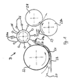
- the device shown in Fig. 1 for the processing of fiber-containing plant material is shown only schematically. It is a device which is enclosed by a housing, not shown, and is possibly carried by a mobile base.
- the stalk material cut on the field is introduced into the opening of a conveying channel 21 at 20 with the aid of a conveyor belt, a slide or a so-called pick-up device (not shown).
- the conveyor channel 21 is formed from a rotatably mounted conveyor roller 22 and a guide plate 23 surrounding the conveyor roller 22 in its lower circumferential area at a selectable distance, which ends at its end remote from the channel opening in a so-called impact surface 24 with an edge 24a, the function of which follows is described in more detail.
- the axis of the conveyor roller 22 can be elastically supported by the distance of the roller circumference from the guide plate 23 of the conveyor to be able to change channel 21.
- the guide plate 23 itself can also be adjustable in order to be able to control the quantity of clippings flowing through the conveying channel 21 or the flow rate through the conveying channel 21 or the force relationships in the conveying channel 21.
- the parameters mentioned are of crucial importance for the degree of disintegration of the plant bodies which can be achieved with the aid of the impact-pull-tear and pressing tool 25 arranged after the conveying channel 21.
- the tool 25 is designed as a striking wheel 25, on the circumference of which cylindrical hammer members 26 are arranged.
- the individual hammer members 26 are seated either on rigid stems 26a movably attached to the striking wheel 26 or on elastic stems rigidly attached to the striking wheel 25.
- the striking wheel 25 itself can also be mounted elastically in order to be able to regulate the effect of the hammer members 26 on the plant material sliding over the striking surface 24, since the distance between the striking wheel 25 and the striking surface 24 also determines the degree of digestion of the plant material which can be achieved with the device.
- a hammer head 30 is approximately cuboid. Its surfaces 30a and 30b, which are essential in cooperation with the striking surface 24 and its edge 24a, are rounded off at their abutting edge 30c. With such a hammer head, the stem of which is movably attached to the striking wheel 25, an impact and pulling effect on the plant material is essentially achieved.
- the striking surface 31 a is greatly rounded at 31 b.
- a uniform impact-pull-tear and pressing effect is achieved, whereas with a hammer head 32 with a greatly shortened impact surface 32a, which bluntly changes into the flat-curved (large radius of curvature) surface, the pressing effect achieved is in the foreground, but the impact - and pulling action is only slight.
- the striking surface 33a of which is part of a half cylinder 33b the striking, pulling and pressing action are approximately balanced.
- the striking elements 34 and 35 are formed from flat, hook-shaped, elastic sheet metal. Your stems are rigidly connected to the impact wheel 25. With a flat hook 34a, a strong pressing effect is predominantly achieved. Its impact and pulling effects are of minor importance, but the pulling effect is in any case so great that the plant material is transported on.
- the striking element designed as a hook 35 is bent in its end region with a small radius of curvature 35a. In the case of such a striking element, the striking, pressing and pulling action are approximately balanced against one another.
- the circumferential speed of the conveying roller 22 and thus the flow speed of the plant material in the conveying channel is chosen to be smaller than the circumferential speed of the hammer members 26 of the striking wheel 25.
- the individual hammer members 26 meet those over the striking surface 24 the straws 24a fed in, compressed and retained in the conveying channel 21 and torn open.
- the length of the striking surface 24 must be selected depending on the difference in the speeds of the plant material supplied and the hammer members 26 and / or on the ratio between the hammer members 26 and the hammer members 26 and the restraining force generated in the conveying channel 21.
- the channel diameter can be changed, for example, by changing the mounting of the conveyor roller 22 to be changed. If the amount of plant material supplied remains the same, the restraining force exerted on the flowing plant material is increased when the channel diameter is reduced. The individual stalks are more compacted and flow at reduced speed over the striking surface 24. With the rotational speed of the striking wheel 25 unchanged, the plant material in the conveying channel 21 is thus retained more strongly with a constant pull exerted by the hammer members 26 on the plant material supplied. The speed difference between the speed of the plant material and the hammer speed increases and thus the degree of digestion of the entire device improves.
- blow-pull-tear-press device tears open in its longitudinal direction the stalks that have been brought together across the striking surface, but that the individual stalks are not knocked off, severed and shortened by the impact action of the device.
- the digested plant material then follows the arrows 27 without being whirled around like in the conventional hammer mills, and is between two counter-rotating rollers 28, 28 a passed and optionally subsequently compressed into a mat.
- the digested plant material can also be immediately loosely stored in the field for drying.
- the surface of the rollers 28, 28a can be circular in cross-section, as shown in the drawing. But it is also conceivable that the surface of these rollers is wave-shaped (see FIG. 3) and that the two rollers mesh with one another in order to immediately create a mat of particularly large surface area and high compaction, which then passes through without any further device must be placed on the field to dry. Also, as shown in Fig. 2, two rollers 28 a and b of smaller diameter can oppose the roller 28 with a large diameter.
- the device for opening the plant material with a separator direction 29 is combined.
- the plant material is separated from its root ball immediately below the feed roller 22.
- the feed roller 22 is then preferably formed with a particularly rough surface and shielded from the front by a deflector plate 30.
- This deflector plate 30 has the task of feeding the entire plant material to the separating device 29.
- FIG. 3 A particularly complex, but at the same time also more effective device for disintegrating plant material is shown in FIG. 3.
- a rotatable rake in the form of a roller brush 1, which is used to align the upright plant material uniformly in the conveying direction of the device and to feed it to the input device 2.
- the input device 2 here consists of a roller 3 with rigid members movably arranged on its circumference, which grasp the plant material supplied and insert it into a conveyor channel 6 provided between a housing wall 5 and the effective range of the input device 2.
- a Separating device 7, here a knife arranged in the bottom area of device 2 is mounted displaceably in the conveying direction. It is dependent on the stalk height of the crop to be cut so that the stalks are only separated from their root ball when they are already aligned in the conveying direction due to the activity of the roller brush 1 and the roller 3.
- the stalks fed to the channel 6 are combined over a large area and fed to the first area for opening up the plant material.
- the feed rate of the plant material is controlled here by a baffle 8 protruding into the channel 6.
- a first area B1 for unlocking the plant material comprises a conveyor roller 9, which determines the feed rate of the plant body to a striking tool 10.
- the plant bodies are guided in a continuation of the channel 6, which is also defined by the housing wall 5 and the outer surface of the conveyor roller 9.
- the housing wall ends in a striking surface 5a, over which the plant bodies are guided and exposed to the striking tool 10.
- the striking tool 10 is here a rotatably mounted roller body 11 with radially outwardly projecting, but rigidly attached to the roller body 11, but elastic members 12.
- the rotational speed of the roller 11 is chosen so that its Circumferential speed is higher than the conveying speed of the conveying roller 9.
- the digested plant bodies which are conveyed further between the housing wall 5 and the roller body 10 are fed to two counter-rotating conveyor rollers 13 and 14.
- the surface of these conveyor rollers 13 and 14 is wave-shaped, the troughs running parallel to the roller axis.
- the conveyor rollers 13 and 14 are spring-loaded and press the digested plant bodies fed to them strongly into a mat. This is given a wavy surface shape.
- a scraper 15 which is molded onto the surface shape of the conveyor rollers 13 and 14, the pressed and shaped mat is stripped from the roller surface and deposited for drying on the field.
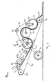
- the device shown in FIG. 4 has been developed, which makes it possible to freely compress the disrupted plant bodies and also to smooth the surface of the mats before they are placed on the field.
- the one of the areas B, B1, B2, B ... n downstream for unlocking the plant material comprises two independently rotating conveyor belts 36 and 37.
- the conveyor belt 36 is moved by the conveyor rollers 38, 39 and 40, the conveyor belt 37 by the conveyor rollers 41, 42 and 43 rotating in the opposite direction to the rollers 38, 39 and 40.
- the disintegrated plant material coming from the region B n -1 is transported to the conveyor roller 41 and passes under the conveyor belt 37, which is moved at a short distance from the conveyor belt 36 in the same direction as this.
- the tracks of both conveyor belts 36 and 37 then run parallel to one another, first under the conveyor roller 41 to the conveyor roller 39, over this to the conveyor roller 43.
- the arrangement of the two conveyor rollers 41 and 43 is such that they act as pressure rollers for the the circumference of the conveyor roller 39 guided web sections of the two conveyor belts 36 and 37 serve.
- the pressure rollers 41 and 43 are each connected to a pivot arm 44 and 45, which in turn controls the position of the pressure rollers 41 via a spring device (not shown) , 43 determine relative to the conveyor roller 39. This prevents excessive tension being exerted on the conveyor belts 36, 37.
- the conveyor rollers 39 and 41 are driven by a drive roller 46, which is connected to the shaft 48 of the conveyor roller 41 via a coupling belt 47.
- the rotational speed of the conveying roller 41 41 can be transmitted to the conveying roller 39 with a corresponding transmission ratio via a gear transmission 49, 50.
- the conveyor belt 37 slides along with its smooth surface along the surface of the planting material located between the conveyor belts 36 and 37 and smoothes the surface of the compacted mat formed by the contact pressure of the press rolls.
- the rollers 38 and 40 or 42 and 43 are idle rollers, which have no special function. It should be pointed out again that while the surface of the conveyor belt 36 facing the crop is relatively rough, the outer surface of the conveyor belt 37 is smooth.
- the digested plant fibers not only experience a definable pressing pressure, but at the same time a certain shear force is exerted on the between by the surface properties of the opposing conveyor belts 36 and 37 during the forward movement plant material located on the conveyor belts.
- the latter in conjunction with the pressing pressure, leads to a strong matting of the plant fibers, a mat having a relatively smooth surface being formed, for example due to the smooth surface of the conveyor belt 37, which mat is removed from the two conveyor belts with the aid of the wipers 50 and 50a provided at the outlet of the device 36 and 37 relieved and onto the field can be placed.
- This device B n comprises a rotating conveyor belt 51, which is driven by the conveyor rollers 52, 53, 54.
- the device B n for breaking up the plant material is connected upstream of the device C for producing the mat from the broken-down plant fibers. It also uses a portion of the conveyor belt 36.
- the conveyor rollers 53 and 54 are arranged so that the belt section of the conveyor belt 51 running between them runs parallel to the conveyor belt 36 at a short distance.
- the direction of rotation of the conveyor rollers 52, 53 and 54 is opposite to that of the rollers 38, 39 and 40.
- the belt speed of the conveyor belt 51 is, however, very much higher than the path speed of the conveyor belt 36.
Landscapes
- Life Sciences & Earth Sciences (AREA)
- Environmental Sciences (AREA)
- Botany (AREA)
- Pretreatment Of Seeds And Plants (AREA)
- Dry Formation Of Fiberboard And The Like (AREA)
- Yarns And Mechanical Finishing Of Yarns Or Ropes (AREA)
- Hydroponics (AREA)
- Inorganic Fibers (AREA)
- Paper (AREA)
- Preliminary Treatment Of Fibers (AREA)
Applications Claiming Priority (4)
| Application Number | Priority Date | Filing Date | Title |
|---|---|---|---|
| DE3928717 | 1989-08-30 | ||
| DE19893928717 DE3928717A1 (de) | 1989-08-30 | 1989-08-30 | Verfahren und vorrichtung zum aufbereiten von faserhaltigen pflanzenkoerpern |
| DE19893942404 DE3942404A1 (de) | 1989-12-21 | 1989-12-21 | Verfahren und vorrichtung zum aufbereiten von faserhaltigen pflanzenkoerpern |
| DE3942404 | 1989-12-21 |
Publications (2)
| Publication Number | Publication Date |
|---|---|
| EP0415380A1 true EP0415380A1 (fr) | 1991-03-06 |
| EP0415380B1 EP0415380B1 (fr) | 1995-05-24 |
Family
ID=25884580
Family Applications (1)
| Application Number | Title | Priority Date | Filing Date |
|---|---|---|---|
| EP90116533A Revoked EP0415380B1 (fr) | 1989-08-30 | 1990-08-29 | Procédé et dispositif pour la préparation des corps de plantes contenant des fibres |
Country Status (3)
| Country | Link |
|---|---|
| EP (1) | EP0415380B1 (fr) |
| AT (1) | ATE122844T1 (fr) |
| DE (2) | DE9012354U1 (fr) |
Cited By (9)
| Publication number | Priority date | Publication date | Assignee | Title |
|---|---|---|---|---|
| DE4033879A1 (de) * | 1990-10-24 | 1992-04-30 | Krone Bernhard Gmbh Maschf | Verfahren und maschine zum aufbereiten von halmgut |
| EP0525553A1 (fr) * | 1991-07-31 | 1993-02-03 | Siegfried Schuster | Dispositif pour former un paillasson |
| EP0543312A1 (fr) * | 1991-11-22 | 1993-05-26 | Maschinenfabrik Bernard Krone GmbH | Procédé de conditionnement de produits de tiges ou de feuilles fauchés et andainés dans la même opération ou avant, et machine de conditionnement pour exécuter ce procédé |
| DE4138360A1 (de) * | 1991-11-22 | 1993-05-27 | Krone Bernhard Gmbh Maschf | Verfahren zur aufbereitung von gemaehtem, in schwaden liegendem halmgut und aufbereitungsmaschine zur durchfuehrung dieses verfahrens |
| DE4138358A1 (de) * | 1991-11-22 | 1993-05-27 | Krone Bernhard Gmbh Maschf | Verfahren zur aufbereitung von gemaehtem, in schwaden liegendem halmgut und aufbereitungsmaschine zur durchfuehrung dieses verfahrens |
| EP0639323A3 (fr) * | 1993-08-17 | 1995-04-26 | Kloeckner Humboldt Deutz Ag | Récolteuse pour la préparation de fourrage. |
| US6052975A (en) * | 1997-08-04 | 2000-04-25 | New Holland North America, Inc. | Method for treating plant material |
| NL1015966C2 (nl) * | 2000-08-18 | 2002-02-19 | Hempron B V | Inrichting en werkwijze voor het oogsten van vezelgewassen. |
| DE10136879B4 (de) * | 2001-07-24 | 2015-03-12 | Alexander Beimler | Verfahren und Vorrichtung zur Ernte von Langhalmkulturen |
Families Citing this family (4)
| Publication number | Priority date | Publication date | Assignee | Title |
|---|---|---|---|---|
| DE4138012A1 (de) * | 1991-11-19 | 1993-05-27 | Kloeckner Humboldt Deutz Ag | Einrichtung zur halmgutdosierung |
| WO1998042179A1 (fr) * | 1997-03-26 | 1998-10-01 | Kverneland Taarup As | Machine pour le conditionnement de cultures |
| DE19925134A1 (de) * | 1999-06-02 | 2000-12-07 | Ake Innotech Automatisierung K | Verfahren und Vorrichtung zum Herstellen von Wirrfasermaterial aus Pflanzenteilen |
| AUPR638301A0 (en) * | 2001-07-13 | 2001-08-09 | Innotech Pty Ltd | Hay conditioner |
Citations (9)
| Publication number | Priority date | Publication date | Assignee | Title |
|---|---|---|---|---|
| DE2643081A1 (de) * | 1975-10-23 | 1977-05-05 | Bucher Guyer Ag Masch | Einrichtung an einem maehwerk zum aufbereiten landwirtschaftlicher halmgueter und verwendung dieser einrichtung |
| DE3320717A1 (de) * | 1983-06-08 | 1984-12-13 | Klöckner-Humboldt-Deutz AG Zweigniederlassung Fahr, 7702 Gottmadingen | Futteraufbereitungsmaschine |
| US4524575A (en) * | 1984-03-12 | 1985-06-25 | Nilsen Arnold W | Windrow aerator |
| DE3415753A1 (de) * | 1984-04-27 | 1985-10-31 | Landtechnik Günter Grube, 2880 Brake | Verfahren und vorrichtung zum aufbereiten von gras |
| DD229576A5 (de) * | 1984-02-06 | 1985-11-13 | Szolnoki Mezoegazdasagi Gepgya | Einrichtung zur verarbeitung von maisstroh |
| EP0205206A1 (fr) * | 1985-06-04 | 1986-12-17 | Multinorm B.V. | Appareil de traitement de fourrage |
| GB2183134A (en) * | 1984-10-31 | 1987-06-03 | Nat Res Dev | Apparatus for treating crop |
| DE2917191C2 (fr) * | 1978-04-28 | 1989-06-08 | Purdue Research Foundation, Lafayette, Ind., Us | |
| AT389418B (de) * | 1978-06-13 | 1989-12-11 | Kuhn Sa | Futtererntemaschine |
-
1990
- 1990-08-29 AT AT90116533T patent/ATE122844T1/de not_active IP Right Cessation
- 1990-08-29 DE DE9012354U patent/DE9012354U1/de not_active Expired - Lifetime
- 1990-08-29 EP EP90116533A patent/EP0415380B1/fr not_active Revoked
- 1990-08-29 DE DE59009121T patent/DE59009121D1/de not_active Expired - Fee Related
Patent Citations (9)
| Publication number | Priority date | Publication date | Assignee | Title |
|---|---|---|---|---|
| DE2643081A1 (de) * | 1975-10-23 | 1977-05-05 | Bucher Guyer Ag Masch | Einrichtung an einem maehwerk zum aufbereiten landwirtschaftlicher halmgueter und verwendung dieser einrichtung |
| DE2917191C2 (fr) * | 1978-04-28 | 1989-06-08 | Purdue Research Foundation, Lafayette, Ind., Us | |
| AT389418B (de) * | 1978-06-13 | 1989-12-11 | Kuhn Sa | Futtererntemaschine |
| DE3320717A1 (de) * | 1983-06-08 | 1984-12-13 | Klöckner-Humboldt-Deutz AG Zweigniederlassung Fahr, 7702 Gottmadingen | Futteraufbereitungsmaschine |
| DD229576A5 (de) * | 1984-02-06 | 1985-11-13 | Szolnoki Mezoegazdasagi Gepgya | Einrichtung zur verarbeitung von maisstroh |
| US4524575A (en) * | 1984-03-12 | 1985-06-25 | Nilsen Arnold W | Windrow aerator |
| DE3415753A1 (de) * | 1984-04-27 | 1985-10-31 | Landtechnik Günter Grube, 2880 Brake | Verfahren und vorrichtung zum aufbereiten von gras |
| GB2183134A (en) * | 1984-10-31 | 1987-06-03 | Nat Res Dev | Apparatus for treating crop |
| EP0205206A1 (fr) * | 1985-06-04 | 1986-12-17 | Multinorm B.V. | Appareil de traitement de fourrage |
Cited By (12)
| Publication number | Priority date | Publication date | Assignee | Title |
|---|---|---|---|---|
| DE4033879A1 (de) * | 1990-10-24 | 1992-04-30 | Krone Bernhard Gmbh Maschf | Verfahren und maschine zum aufbereiten von halmgut |
| EP0525553A1 (fr) * | 1991-07-31 | 1993-02-03 | Siegfried Schuster | Dispositif pour former un paillasson |
| EP0543312A1 (fr) * | 1991-11-22 | 1993-05-26 | Maschinenfabrik Bernard Krone GmbH | Procédé de conditionnement de produits de tiges ou de feuilles fauchés et andainés dans la même opération ou avant, et machine de conditionnement pour exécuter ce procédé |
| DE4138360A1 (de) * | 1991-11-22 | 1993-05-27 | Krone Bernhard Gmbh Maschf | Verfahren zur aufbereitung von gemaehtem, in schwaden liegendem halmgut und aufbereitungsmaschine zur durchfuehrung dieses verfahrens |
| DE4138358A1 (de) * | 1991-11-22 | 1993-05-27 | Krone Bernhard Gmbh Maschf | Verfahren zur aufbereitung von gemaehtem, in schwaden liegendem halmgut und aufbereitungsmaschine zur durchfuehrung dieses verfahrens |
| EP0639323A3 (fr) * | 1993-08-17 | 1995-04-26 | Kloeckner Humboldt Deutz Ag | Récolteuse pour la préparation de fourrage. |
| US6052975A (en) * | 1997-08-04 | 2000-04-25 | New Holland North America, Inc. | Method for treating plant material |
| US6058689A (en) * | 1997-08-04 | 2000-05-09 | New Holland North America, Inc. | Apparatus for treating plant material |
| US6062010A (en) * | 1997-08-04 | 2000-05-16 | New Holland North America, Inc. | Apparatus for treating plant material |
| NL1015966C2 (nl) * | 2000-08-18 | 2002-02-19 | Hempron B V | Inrichting en werkwijze voor het oogsten van vezelgewassen. |
| EP1181859A1 (fr) * | 2000-08-18 | 2002-02-27 | Hempron B.V. | Appareil et procédé de récolte de plantes à fibres |
| DE10136879B4 (de) * | 2001-07-24 | 2015-03-12 | Alexander Beimler | Verfahren und Vorrichtung zur Ernte von Langhalmkulturen |
Also Published As
| Publication number | Publication date |
|---|---|
| DE59009121D1 (de) | 1995-06-29 |
| ATE122844T1 (de) | 1995-06-15 |
| DE9012354U1 (de) | 1990-12-06 |
| EP0415380B1 (fr) | 1995-05-24 |
Similar Documents
| Publication | Publication Date | Title |
|---|---|---|
| DE69214829T2 (de) | Brechvorrichtung | |
| AT396948B (de) | Verfahren und vorrichtung zum entholzen und zum aufbereiten von flachs | |
| EP0408850B1 (fr) | Moissonneuse automotrice | |
| DE2917191C2 (fr) | ||
| EP0415380B1 (fr) | Procédé et dispositif pour la préparation des corps de plantes contenant des fibres | |
| DE69813518T2 (de) | Vorrichtung zur herstellung von fasern | |
| DE4036717A1 (de) | Pflueckvorsatz fuer ein erntegeraet | |
| CH622033A5 (fr) | ||
| EP0135724B1 (fr) | Récolte use à rangs multiples, notamment pour mais | |
| DE1816117A1 (de) | Verfahren und Vorrichtung zum Trennen der unterschiedlichen Bestandteile von Zuckerrohr | |
| DD271254A1 (de) | Vorrichtung zum entholzen von pflanzen mit langen fasern auf dem feld | |
| CH626660A5 (fr) | ||
| DE69210827T2 (de) | Ausrichtungsvorrichtung | |
| CH667287A5 (de) | Karde und verfahren zu deren betrieb. | |
| DE3786267T2 (de) | Verfahren und Vorrichtung zur kontinuierlichen Aufbereitung von Pflanzenstengeln. | |
| EP0369440A1 (fr) | Procédé et appareil pour récolter les fruits sur pied | |
| DE102011013242B4 (de) | Ballenpresse | |
| DE7801619U1 (de) | Kardiermaschine | |
| CH669610A5 (fr) | ||
| DE69211142T2 (de) | Trennvorrichtung für Fasern und Pflanzenreste | |
| DE202007007213U1 (de) | Schneidkopf für selbstfahrende Häckselmaschinen zum Abscheren hochstämmiger Pflanzen | |
| DE69228506T2 (de) | Maschine zum Bearbeiten von halmähnlichen Gewächsen | |
| WO2007033504A1 (fr) | Dispositif pour le traitement de fibres sur le tambour d'une carde | |
| DE69521062T2 (de) | Speiseschacht für textilverfahrensanlage | |
| DE4344585A1 (de) | Vorrichtung zur Halmgutaufbereitung |
Legal Events
| Date | Code | Title | Description |
|---|---|---|---|
| PUAI | Public reference made under article 153(3) epc to a published international application that has entered the european phase |
Free format text: ORIGINAL CODE: 0009012 |
|
| 17P | Request for examination filed |
Effective date: 19901126 |
|
| AK | Designated contracting states |
Kind code of ref document: A1 Designated state(s): AT CH DE FR LI NL |
|
| 17Q | First examination report despatched |
Effective date: 19920609 |
|
| GRAA | (expected) grant |
Free format text: ORIGINAL CODE: 0009210 |
|
| AK | Designated contracting states |
Kind code of ref document: B1 Designated state(s): AT CH DE FR LI NL |
|
| REF | Corresponds to: |
Ref document number: 122844 Country of ref document: AT Date of ref document: 19950615 Kind code of ref document: T |
|
| ET | Fr: translation filed | ||
| REF | Corresponds to: |
Ref document number: 59009121 Country of ref document: DE Date of ref document: 19950629 |
|
| PLBQ | Unpublished change to opponent data |
Free format text: ORIGINAL CODE: EPIDOS OPPO |
|
| PLAV | Examination of admissibility of opposition |
Free format text: ORIGINAL CODE: EPIDOS OPEX |
|
| PLBI | Opposition filed |
Free format text: ORIGINAL CODE: 0009260 |
|
| PLAV | Examination of admissibility of opposition |
Free format text: ORIGINAL CODE: EPIDOS OPEX |
|
| PLBF | Reply of patent proprietor to notice(s) of opposition |
Free format text: ORIGINAL CODE: EPIDOS OBSO |
|
| 26 | Opposition filed |
Opponent name: SAME S.P.A. Effective date: 19960223 Opponent name: MASCHINENFABRIKEN BERNHARD KRONE GMBH Effective date: 19960220 |
|
| NLR1 | Nl: opposition has been filed with the epo |
Opponent name: SAME S.P.A. Opponent name: MASCHINENFABRIKEN BERNHARD KRONE GMBH |
|
| PLBF | Reply of patent proprietor to notice(s) of opposition |
Free format text: ORIGINAL CODE: EPIDOS OBSO |
|
| PLBF | Reply of patent proprietor to notice(s) of opposition |
Free format text: ORIGINAL CODE: EPIDOS OBSO |
|
| PLBQ | Unpublished change to opponent data |
Free format text: ORIGINAL CODE: EPIDOS OPPO |
|
| PLAB | Opposition data, opponent's data or that of the opponent's representative modified |
Free format text: ORIGINAL CODE: 0009299OPPO |
|
| R26 | Opposition filed (corrected) |
Opponent name: MASCHINENFABRIKEN BERNHARD KRONE GMBH * 960223 SAM Effective date: 19960220 |
|
| NLR1 | Nl: opposition has been filed with the epo |
Opponent name: SAME S.P.A. Opponent name: MASCHINENFABRIKEN BERNHARD KRONE GMBH |
|
| PGFP | Annual fee paid to national office [announced via postgrant information from national office to epo] |
Ref country code: FR Payment date: 19970829 Year of fee payment: 8 |
|
| PGFP | Annual fee paid to national office [announced via postgrant information from national office to epo] |
Ref country code: NL Payment date: 19970831 Year of fee payment: 8 |
|
| PLBQ | Unpublished change to opponent data |
Free format text: ORIGINAL CODE: EPIDOS OPPO |
|
| PLBQ | Unpublished change to opponent data |
Free format text: ORIGINAL CODE: EPIDOS OPPO |
|
| PLAB | Opposition data, opponent's data or that of the opponent's representative modified |
Free format text: ORIGINAL CODE: 0009299OPPO |
|
| R26 | Opposition filed (corrected) |
Opponent name: MASCHINENFABRIKEN BERNHARD KRONE GMBH * 960223 SAM Effective date: 19960220 |
|
| NLR1 | Nl: opposition has been filed with the epo |
Opponent name: SAME S.P.A. Opponent name: MASCHINENFABRIKEN BERNHARD KRONE GMBH |
|
| PG25 | Lapsed in a contracting state [announced via postgrant information from national office to epo] |
Ref country code: NL Free format text: LAPSE BECAUSE OF NON-PAYMENT OF DUE FEES Effective date: 19990301 |
|
| PG25 | Lapsed in a contracting state [announced via postgrant information from national office to epo] |
Ref country code: FR Free format text: LAPSE BECAUSE OF NON-PAYMENT OF DUE FEES Effective date: 19990430 |
|
| NLV4 | Nl: lapsed or anulled due to non-payment of the annual fee |
Effective date: 19990301 |
|
| REG | Reference to a national code |
Ref country code: FR Ref legal event code: ST |
|
| PGFP | Annual fee paid to national office [announced via postgrant information from national office to epo] |
Ref country code: AT Payment date: 19990827 Year of fee payment: 10 |
|
| PGFP | Annual fee paid to national office [announced via postgrant information from national office to epo] |
Ref country code: CH Payment date: 19990903 Year of fee payment: 10 |
|
| PG25 | Lapsed in a contracting state [announced via postgrant information from national office to epo] |
Ref country code: AT Free format text: LAPSE BECAUSE OF NON-PAYMENT OF DUE FEES Effective date: 20000829 |
|
| PG25 | Lapsed in a contracting state [announced via postgrant information from national office to epo] |
Ref country code: LI Free format text: LAPSE BECAUSE OF NON-PAYMENT OF DUE FEES Effective date: 20000831 Ref country code: CH Free format text: LAPSE BECAUSE OF NON-PAYMENT OF DUE FEES Effective date: 20000831 |
|
| PGFP | Annual fee paid to national office [announced via postgrant information from national office to epo] |
Ref country code: DE Payment date: 20010322 Year of fee payment: 11 |
|
| REG | Reference to a national code |
Ref country code: CH Ref legal event code: PL |
|
| PLAW | Interlocutory decision in opposition |
Free format text: ORIGINAL CODE: EPIDOS IDOP |
|
| PLAW | Interlocutory decision in opposition |
Free format text: ORIGINAL CODE: EPIDOS IDOP |
|
| PG25 | Lapsed in a contracting state [announced via postgrant information from national office to epo] |
Ref country code: DE Free format text: LAPSE BECAUSE OF NON-PAYMENT OF DUE FEES Effective date: 20020501 |
|
| RDAH | Patent revoked |
Free format text: ORIGINAL CODE: EPIDOS REVO |
|
| RDAG | Patent revoked |
Free format text: ORIGINAL CODE: 0009271 |
|
| STAA | Information on the status of an ep patent application or granted ep patent |
Free format text: STATUS: PATENT REVOKED |
|
| 27W | Patent revoked |
Effective date: 20020803 |