EP0415781A2 - Dispositif d'inclinaison à double verrouillage pour sièges d'automobiles - Google Patents
Dispositif d'inclinaison à double verrouillage pour sièges d'automobiles Download PDFInfo
- Publication number
- EP0415781A2 EP0415781A2 EP90309549A EP90309549A EP0415781A2 EP 0415781 A2 EP0415781 A2 EP 0415781A2 EP 90309549 A EP90309549 A EP 90309549A EP 90309549 A EP90309549 A EP 90309549A EP 0415781 A2 EP0415781 A2 EP 0415781A2
- Authority
- EP
- European Patent Office
- Prior art keywords
- lever
- recliner
- seat
- locking
- base plate
- Prior art date
- Legal status (The legal status is an assumption and is not a legal conclusion. Google has not performed a legal analysis and makes no representation as to the accuracy of the status listed.)
- Granted
Links
- 230000001360 synchronised effect Effects 0.000 claims description 3
- 238000010276 construction Methods 0.000 description 9
- 238000009434 installation Methods 0.000 description 3
Images

Classifications
-
- B—PERFORMING OPERATIONS; TRANSPORTING
- B60—VEHICLES IN GENERAL
- B60N—SEATS SPECIALLY ADAPTED FOR VEHICLES; VEHICLE PASSENGER ACCOMMODATION NOT OTHERWISE PROVIDED FOR
- B60N2/00—Seats specially adapted for vehicles; Arrangement or mounting of seats in vehicles
-
- B—PERFORMING OPERATIONS; TRANSPORTING
- B60—VEHICLES IN GENERAL
- B60N—SEATS SPECIALLY ADAPTED FOR VEHICLES; VEHICLE PASSENGER ACCOMMODATION NOT OTHERWISE PROVIDED FOR
- B60N2/00—Seats specially adapted for vehicles; Arrangement or mounting of seats in vehicles
- B60N2/02—Seats specially adapted for vehicles; Arrangement or mounting of seats in vehicles the seat or part thereof being movable, e.g. adjustable
- B60N2/22—Seats specially adapted for vehicles; Arrangement or mounting of seats in vehicles the seat or part thereof being movable, e.g. adjustable the back-rest being adjustable
- B60N2/235—Seats specially adapted for vehicles; Arrangement or mounting of seats in vehicles the seat or part thereof being movable, e.g. adjustable the back-rest being adjustable by gear-pawl type mechanisms
- B60N2/2352—Seats specially adapted for vehicles; Arrangement or mounting of seats in vehicles the seat or part thereof being movable, e.g. adjustable the back-rest being adjustable by gear-pawl type mechanisms with external pawls
-
- B—PERFORMING OPERATIONS; TRANSPORTING
- B60—VEHICLES IN GENERAL
- B60N—SEATS SPECIALLY ADAPTED FOR VEHICLES; VEHICLE PASSENGER ACCOMMODATION NOT OTHERWISE PROVIDED FOR
- B60N2205/00—General mechanical or structural details
- B60N2205/40—Dual or redundant actuating means, e.g. backrest tilting can be actuated alternatively by a lever at the backrest or a lever in the luggage compartment
Definitions
- the present invention relates generally to a recliner for adjusting reclining position of a seat back of an automotive seat. More specifically, the invention relates to a double lock recliner which includes a pair of recliner devices at both sides of an automotive seat.
- an automotive seat is capable of adjusting tilting angle of a seat back relative to a seat cushion so as to permit adjustment of seating position of the seat occupant.
- a recliner is provided for permitting pivotal movement of the seat back relative to the seat cushion.
- the seat recliner includes a singular recliner device oriented one side of the seat and a pivot device at the other side of the seat.
- the pivot device since the pivot device has no capability of locking of the seat at the selected reclining position or tilting position of the seat back, distortion or twisting of the seat back can be caused to degrade comfort at the seat.
- the recently proposed double lock recliner which has symmetric recliner devices at both sides of the seat. Because the recliner devices are provided at both sides of the seat, locking at respective recliner device has to be released. As can be naturally appreciated, independent lock releasing operation for respective recliner device should be too cumbersome or troublesome for the seat occupant and thus is preferred to be avoided.
- the recently proposed double lock recliner comprises a primary recliner device which incorporates a release structure operable by means of a manually operable release lever for releasing locking, and a auxiliary recliner device to be oriented at the side opposite to the primary recliner device.
- the auxiliary recliner device is connected to the primary recliner device by means of a rotary lever.
- the link lever carries a pivotal lever which is connected to an operation lever pivotally mounted on a base plate.
- the operation lever carries an operation pin associated with an elongated slot formed through the base plate.
- the operation pin is connected to an actuation level associated with a locking tooth member.
- the operational input through the manually operable release lever of the primary recliner device can be transferred through the rotary lever for synchronous operation of the auxiliary recliner device.
- a buckle device for a safety belt is to be provided one side of the seat.
- the buckle device is normally provided at inner side (side adjacent the center line of the vehicle) of the seat, where the auxiliary recliner device can be provided.
- the buckle device can interfere pivotal movement of the pivotal lever set forth above.
- the base plate has to be large enough to permit installation of the buckle device with the auxiliary recliner device.
- a double lock seat recliner has a primary recliner device and a secondary recliner device are connected by a rotary linking rod:
- a first lever pivotally mounted on a pivot of a release lever.
- a second lever is connected with the first lever by means of a connecting pin.
- the second lever is cooperated to the rotary linking rod.
- a third lever is pivotally cooperated with the rotary lever.
- a fourth lever is pivotally connected to the third lever via a connecting pin.
- the fourth lever is cooperated with a pivot shaft of a locking member of the auxiliary recliner device.
- the third lever is mounted on the inner side of a base plate.
- the fourth lever is mounted on the out side of the base plate.
- the connecting pin for cooperably connecting the third lever with the fourth lever extends through an elongated slot formed through the base plate.
- a double lock seat recliner for an automotive seat comprises: a first recliner device including a first locking mechanism for establishing engagement for locking a seat back of the seat at a selected reclining position, a manually operable release lever, a first lock release mechanism including a first lever means cooperated with the release lever for pivotal movement in response to manual operation of the lock release lever, the first lever means being pivotably mounted on one side of a first base plate; a second recliner device including a second locking mechanism for establishing engagement for locking a seat back of the seat at a selected reclining position, a manually operable release lever, a second lock release mechanism including a second lever means cooperated with the release lever for pivotal movement in response to manual operation of the lock release lever, the second lever means being pivotably mounted on one side of a second base plate; and means for cooperating the first and second recliner devices for synchroneous operation, the cooperating means including a rotary rod extending between the first and second recliner devices and first and second connecting
- the second elongated hole may be differentiated in configuration from the first elongated hole so as to permit independent lock release operation irrespective of the first recliner device.
- the first elongated hole may be so constructed to permit movement of the first connecting pin in a first direction during locking and unlocking operation of the first locking mechanism, and the second elongated hole is so constructed to permit movement of the second connecting pin in the first direction and a second direction essentially perpendicular to the first direction during locking and unlocking operation of the second locking mechanism.
- a primary recliner device is provided at outside of an automotive seat, which word “outside of the seat” is used for identification the orientation transversely remote from the center line of the vehicle, and an auxiliary recliner device is provided at inside of the automotive seat, which word “inside of the seat” is used for identification of the orientation transversely close to the center line of the vehicle and thus opposite to the outside.
- Respective of the primary and the auxiliary recliner devices are provided at rear end positions of the seat.
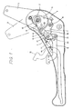
- the primary recliner device has a base plate 1.
- a pivotal arm 3 is rigidly fitted on the outer side portion of a seat back (not shown) of an the automotive seat.
- the pivotal arm 3 is pivotally mounted on a pivot 2.
- a first tooth member 5 which is formed with a locking teeth 4 in a predetermined angular range, is cooperated with the pivotal arm 3.
- a second tooth member 7 is pivotably mounted on the base plate 1 for pivotal movement about a pivot 8.
- the second tooth member 7 is formed with a teeth 6 interengageable with the locking teeth 4 of the first teeth member 4.
- the second teeth member 7 is formed with a recess 9.
- the recess 9 is engageable with a locking projection 10 of a locking member 11 which is cooperated with a release lever 12 for cooperation therewith.
- the release lever 12 is pivotally mounted on the base plate 1 for pivotal movement about a pivot 13.
- the release lever 12 is resiliently biased in counterclockwise direction in Fig. 1 by means of a bias coil spring 14 which is connected to the base plate 1 at one end and to the release lever at the other end.
- a spiral spring 15 is provided.
- the spiral spring 15 has one end engaged with the pivotal arm 3 and the other end engaged with the pivot 2. With this construction, the pivotal arm 3 is biased in clockwise direction in Fig. 1 by means of the spiral spring 15.
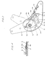
- a pivotal arm 3a is rigidly fitted on the inner side portion of the seat back similarly to the pivotal arm 3 set forth above.
- the pivotal arm 3a is mounted on a base plate 1a via a pivot 2a.
- the pivotal arm 3a is coupled with a first tooth member 5a for pivotal movement therewith.
- the first tooth member 5a is engaged with a second tooth member 7a which is pivotably supported on the base plate 1a about a pivot 8a.
- the second tooth member 7a defines a locking recess 9a which is engagable with a locking projection 10a formed with the locking member 11a which is pivotable about a pivot 13a extended from the base plate 1a.
- the locking member 11a is resiliently biased in clockwise direction by means of a coil spring 14a for pivotal motion about the pivot 13a.
- the pivotal arm 3a is biased in by a spiral spring 15a.
- holder plates 24 and 24a are provided for supporting free ends of respective pivots 2, 8, 13 and 2a, 8a, 13a.
- the pivots 2 and 2a are connected to one another by means of a rotary linking rod 16.
- the linking rod 16 is connected to a second link lever 17 and a third link lever 17a which has different lever length relative to the second link lever.
- a first link lever 18 which is of generally crank shaped configuration in plan view, is rigidly secured to the pivot 13 of the release lever 12.
- the release lever and the the first link lever 18 are interconnected to each other via a connecting pin 21 as shown in Fig. 1.
- the connecting pin 21 extends through an arc shaped elongated slot 23 defined through the base plate 1.
- a fourth link lever 18a is oriented on the outside face of the base plate 1a.
- the fourth link lever 18a is pivotable about the pivot 13a, about which the locking member 11a is pivotally provided, as shown in Fig. 4. Namely, as seen from Fig. 2, a pin 20a extending from the front end of the fourth link lever 18a. The pin 20a extends through an arc shaped slot 22 of Fig. 2. With this construction, even when the seat belt buckle is mounted on the inner face of the base plate 1a, the buckle may not interfere pivotal movement of the fourth link lever 18a. Furthermore, as can be seen, the second link lever 17 is formed at shorter length than the third lever 17a. On the other hand, the fourth link lever 18a is formed with a shorter length than the first link lever 18.
- the second and third link levers 17 and 17a are rigidly secured to both transverse ends of the linkage rod 16 at mutually identical angular relationship with the linkage rod.
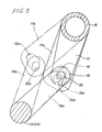
- the first and second link levers 18 and 20 are cooperated by engaging a the connecting pin 20 extending from the end of the first link lever 18, and an elongated hole 19 formed through the second link lever 17 for cooperative movement with each other.
- the fourth lever 18a has a connecting pin 20a engaging with an elongated hole 19a which is differentiated in configuration from that elongated hole 19 as can be seen from Fig. 5.
- the elongated hole 19a is designed to permit the action of the connecting pin 20a in the same direction to that of the connecting pin 20 when the primary and auxiliary recliner devices are cooperated for synchronous operation.
- the elongated hole 19a is also designed for permitting action of the connection pin 20a essentially perpendicular to the motion direction of the connecting pin 20 of the primary recliner device.
- the third link lever 17a which is rigidly fixed with the other end of the linkage rod 16 is driven pivotally.
- the fourth link lever 18a is pivotally moved about the pivot 13a in counterclockwise direction.
- the locking member 11a is pivotally moved in counterclockwise direction.
- the projection 10a of the locking member 11a comes into engagement with the locking recess 9a. Therefore, the second tooth member 7a is driven in clockwise direction about the pivot 8a. Therefore, locking engagement between the first and second tooth members 5a and 7a can be released. Therefore, the pivotal arm 3a becomes free from restriction and thus driven by the spring force of the spiral spring 15a.
Landscapes
- Engineering & Computer Science (AREA)
- Aviation & Aerospace Engineering (AREA)
- Transportation (AREA)
- Mechanical Engineering (AREA)
- Chairs For Special Purposes, Such As Reclining Chairs (AREA)
Applications Claiming Priority (2)
| Application Number | Priority Date | Filing Date | Title |
|---|---|---|---|
| JP1989102337U JPH0742342Y2 (ja) | 1989-08-31 | 1989-08-31 | 両ロックリクライナー用連動装置 |
| JP102337/89 | 1989-08-31 |
Publications (3)
| Publication Number | Publication Date |
|---|---|
| EP0415781A2 true EP0415781A2 (fr) | 1991-03-06 |
| EP0415781A3 EP0415781A3 (en) | 1991-11-06 |
| EP0415781B1 EP0415781B1 (fr) | 1995-10-18 |
Family
ID=14324696
Family Applications (1)
| Application Number | Title | Priority Date | Filing Date |
|---|---|---|---|
| EP90309549A Expired - Lifetime EP0415781B1 (fr) | 1989-08-31 | 1990-08-31 | Dispositif d'inclinaison à double verrouillage pour sièges d'automobiles |
Country Status (4)
| Country | Link |
|---|---|
| EP (1) | EP0415781B1 (fr) |
| JP (1) | JPH0742342Y2 (fr) |
| KR (1) | KR910004395A (fr) |
| DE (1) | DE69023085D1 (fr) |
Cited By (4)
| Publication number | Priority date | Publication date | Assignee | Title |
|---|---|---|---|---|
| EP0505593A1 (fr) * | 1991-03-27 | 1992-09-30 | Fujikiko Kabushiki Kaisha | Dispositif d'inclinaison de siège |
| WO2004026621A1 (fr) * | 2002-09-17 | 2004-04-01 | Keiper Gmbh & Co. Kg | Dispositif de reglage pour siege de vehicule |
| CN108032061A (zh) * | 2018-01-03 | 2018-05-15 | 苏州托克斯冲压设备有限公司 | 一种调角器涡卷簧的装配装置 |
| CN109334521A (zh) * | 2018-11-16 | 2019-02-15 | 广汽零部件有限公司 | 结构简单且调角平稳的汽车座椅靠背骨架角度调节装置 |
Families Citing this family (2)
| Publication number | Priority date | Publication date | Assignee | Title |
|---|---|---|---|---|
| CA2474185C (fr) * | 2002-02-06 | 2012-05-08 | Intier Automotive Inc. | Ensemble d'embrayage de commande rotatif a verrouillage bidirectionnel |
| JP4517748B2 (ja) * | 2004-06-28 | 2010-08-04 | アイシン精機株式会社 | 車両用シートリクライニング装置 |
Family Cites Families (4)
| Publication number | Priority date | Publication date | Assignee | Title |
|---|---|---|---|---|
| DE7415117U (de) * | 1974-04-30 | 1974-08-14 | Keiper F | Gelenkbeschlag zur kippbeweglichen verbindung des sitzteils eines sitzes insbesondere fahrzeugsitzes wie kraftwagensitzes mit der rueckenlehne |
| JPS6051887B2 (ja) * | 1978-10-18 | 1985-11-16 | アイシン精機株式会社 | 自動車用シ−ト傾斜角調節装置 |
| JPS6130535Y2 (fr) * | 1980-05-16 | 1986-09-06 | ||
| AU585402B2 (en) * | 1986-11-07 | 1989-06-15 | Tachi-S Co., Ltd. | Reclining device |
-
1989
- 1989-08-31 JP JP1989102337U patent/JPH0742342Y2/ja not_active Expired - Fee Related
-
1990
- 1990-08-30 KR KR1019900013484A patent/KR910004395A/ko not_active Ceased
- 1990-08-31 EP EP90309549A patent/EP0415781B1/fr not_active Expired - Lifetime
- 1990-08-31 DE DE69023085T patent/DE69023085D1/de not_active Expired - Lifetime
Cited By (7)
| Publication number | Priority date | Publication date | Assignee | Title |
|---|---|---|---|---|
| EP0505593A1 (fr) * | 1991-03-27 | 1992-09-30 | Fujikiko Kabushiki Kaisha | Dispositif d'inclinaison de siège |
| WO2004026621A1 (fr) * | 2002-09-17 | 2004-04-01 | Keiper Gmbh & Co. Kg | Dispositif de reglage pour siege de vehicule |
| US7093902B2 (en) | 2002-09-17 | 2006-08-22 | Keiper Gmbh & Co. Kg | Adjuster for a vehicle seat |
| CN100445125C (zh) * | 2002-09-17 | 2008-12-24 | 凯波有限责任两合公司 | 车辆座椅调节器 |
| CN108032061A (zh) * | 2018-01-03 | 2018-05-15 | 苏州托克斯冲压设备有限公司 | 一种调角器涡卷簧的装配装置 |
| CN108032061B (zh) * | 2018-01-03 | 2024-03-08 | 苏州托克斯冲压设备有限公司 | 一种调角器涡卷簧的装配装置 |
| CN109334521A (zh) * | 2018-11-16 | 2019-02-15 | 广汽零部件有限公司 | 结构简单且调角平稳的汽车座椅靠背骨架角度调节装置 |
Also Published As
| Publication number | Publication date |
|---|---|
| KR910004395A (ko) | 1991-03-28 |
| EP0415781B1 (fr) | 1995-10-18 |
| EP0415781A3 (en) | 1991-11-06 |
| DE69023085D1 (de) | 1995-11-23 |
| JPH0742342Y2 (ja) | 1995-10-04 |
| JPH0342245U (fr) | 1991-04-22 |
Similar Documents
| Publication | Publication Date | Title |
|---|---|---|
| US5224759A (en) | Double lock recliner for automotive seat | |
| US4626028A (en) | Seat for vehicles | |
| US4370000A (en) | Seat for motor vehicles | |
| US4484779A (en) | Double folding mechanism for vehicle seats | |
| JP2000004970A (ja) | リクライニング装置 | |
| JPH08258600A (ja) | 車両用シート装置 | |
| US5718483A (en) | Adjustable hinge mount for seats | |
| JPH08230525A (ja) | 手動6方向シート調節組立体 | |
| US20040135412A1 (en) | Motor vehicle seat | |
| EP0415781A2 (fr) | Dispositif d'inclinaison à double verrouillage pour sièges d'automobiles | |
| GB2283910A (en) | Vehicle seat reclining apparatus | |
| JP2002301965A (ja) | チャイルドシート | |
| WO2007077980A1 (fr) | Siege d'automobile a basculement | |
| EP0505593A1 (fr) | Dispositif d'inclinaison de siège | |
| JPH0120927Y2 (fr) | ||
| JPH024612Y2 (fr) | ||
| JP2535487Y2 (ja) | シートリクライニング装置 | |
| JPH0319783Y2 (fr) | ||
| JPH0644449U (ja) | 車両用シート | |
| JP3344857B2 (ja) | シートリクライニング装置 | |
| JPH0838287A (ja) | 両ロックシートリクライニング装置 | |
| JP2548764Y2 (ja) | シートリクライニング装置 | |
| JP2000041776A (ja) | シートリクライニング装置 | |
| JP2784319B2 (ja) | リクライニング装置 | |
| JPH0651012B2 (ja) | 車両用座席 |
Legal Events
| Date | Code | Title | Description |
|---|---|---|---|
| PUAI | Public reference made under article 153(3) epc to a published international application that has entered the european phase |
Free format text: ORIGINAL CODE: 0009012 |
|
| AK | Designated contracting states |
Kind code of ref document: A2 Designated state(s): DE ES FR GB |
|
| PUAL | Search report despatched |
Free format text: ORIGINAL CODE: 0009013 |
|
| AK | Designated contracting states |
Kind code of ref document: A3 Designated state(s): DE ES FR GB |
|
| 17P | Request for examination filed |
Effective date: 19920422 |
|
| 17Q | First examination report despatched |
Effective date: 19940307 |
|
| GRAA | (expected) grant |
Free format text: ORIGINAL CODE: 0009210 |
|
| AK | Designated contracting states |
Kind code of ref document: B1 Designated state(s): DE ES FR GB |
|
| PG25 | Lapsed in a contracting state [announced via postgrant information from national office to epo] |
Ref country code: FR Effective date: 19951018 Ref country code: ES Free format text: THE PATENT HAS BEEN ANNULLED BY A DECISION OF A NATIONAL AUTHORITY Effective date: 19951018 |
|
| REF | Corresponds to: |
Ref document number: 69023085 Country of ref document: DE Date of ref document: 19951123 |
|
| PG25 | Lapsed in a contracting state [announced via postgrant information from national office to epo] |
Ref country code: DE Effective date: 19960119 |
|
| EN | Fr: translation not filed | ||
| PLBE | No opposition filed within time limit |
Free format text: ORIGINAL CODE: 0009261 |
|
| STAA | Information on the status of an ep patent application or granted ep patent |
Free format text: STATUS: NO OPPOSITION FILED WITHIN TIME LIMIT |
|
| 26N | No opposition filed | ||
| PGFP | Annual fee paid to national office [announced via postgrant information from national office to epo] |
Ref country code: GB Payment date: 19970822 Year of fee payment: 8 |
|
| PG25 | Lapsed in a contracting state [announced via postgrant information from national office to epo] |
Ref country code: GB Free format text: LAPSE BECAUSE OF NON-PAYMENT OF DUE FEES Effective date: 19980831 |
|
| GBPC | Gb: european patent ceased through non-payment of renewal fee |
Effective date: 19980831 |