EP0417945B1 - Improvements relating to a vacuum servo unit for use in traction control - Google Patents
Improvements relating to a vacuum servo unit for use in traction control Download PDFInfo
- Publication number
- EP0417945B1 EP0417945B1 EP90309561A EP90309561A EP0417945B1 EP 0417945 B1 EP0417945 B1 EP 0417945B1 EP 90309561 A EP90309561 A EP 90309561A EP 90309561 A EP90309561 A EP 90309561A EP 0417945 B1 EP0417945 B1 EP 0417945B1
- Authority
- EP
- European Patent Office
- Prior art keywords
- housing
- pressure chamber
- servo unit
- diaphragm
- bypass
- Prior art date
- Legal status (The legal status is an assumption and is not a legal conclusion. Google has not performed a legal analysis and makes no representation as to the accuracy of the status listed.)
- Expired - Lifetime
Links
- 238000010276 construction Methods 0.000 description 2
Images


Classifications
-
- B—PERFORMING OPERATIONS; TRANSPORTING
- B60—VEHICLES IN GENERAL
- B60T—VEHICLE BRAKE CONTROL SYSTEMS OR PARTS THEREOF; BRAKE CONTROL SYSTEMS OR PARTS THEREOF, IN GENERAL; ARRANGEMENT OF BRAKING ELEMENTS ON VEHICLES IN GENERAL; PORTABLE DEVICES FOR PREVENTING UNWANTED MOVEMENT OF VEHICLES; VEHICLE MODIFICATIONS TO FACILITATE COOLING OF BRAKES
- B60T8/00—Arrangements for adjusting wheel-braking force to meet varying vehicular or ground-surface conditions, e.g. limiting or varying distribution of braking force
- B60T8/32—Arrangements for adjusting wheel-braking force to meet varying vehicular or ground-surface conditions, e.g. limiting or varying distribution of braking force responsive to a speed condition, e.g. acceleration or deceleration
- B60T8/34—Arrangements for adjusting wheel-braking force to meet varying vehicular or ground-surface conditions, e.g. limiting or varying distribution of braking force responsive to a speed condition, e.g. acceleration or deceleration having a fluid pressure regulator responsive to a speed condition
- B60T8/48—Arrangements for adjusting wheel-braking force to meet varying vehicular or ground-surface conditions, e.g. limiting or varying distribution of braking force responsive to a speed condition, e.g. acceleration or deceleration having a fluid pressure regulator responsive to a speed condition connecting the brake actuator to an alternative or additional source of fluid pressure, e.g. traction control systems
- B60T8/4809—Traction control, stability control, using both the wheel brakes and other automatic braking systems
- B60T8/4827—Traction control, stability control, using both the wheel brakes and other automatic braking systems in hydraulic brake systems
- B60T8/4845—Traction control, stability control, using both the wheel brakes and other automatic braking systems in hydraulic brake systems using a booster or a master cylinder for traction control
- B60T8/4854—Traction control, stability control, using both the wheel brakes and other automatic braking systems in hydraulic brake systems using a booster or a master cylinder for traction control pneumatic boosters
-
- B—PERFORMING OPERATIONS; TRANSPORTING
- B60—VEHICLES IN GENERAL
- B60T—VEHICLE BRAKE CONTROL SYSTEMS OR PARTS THEREOF; BRAKE CONTROL SYSTEMS OR PARTS THEREOF, IN GENERAL; ARRANGEMENT OF BRAKING ELEMENTS ON VEHICLES IN GENERAL; PORTABLE DEVICES FOR PREVENTING UNWANTED MOVEMENT OF VEHICLES; VEHICLE MODIFICATIONS TO FACILITATE COOLING OF BRAKES
- B60T13/00—Transmitting braking action from initiating means to ultimate brake actuator with power assistance or drive; Brake systems incorporating such transmitting means, e.g. air-pressure brake systems
-
- B—PERFORMING OPERATIONS; TRANSPORTING
- B60—VEHICLES IN GENERAL
- B60T—VEHICLE BRAKE CONTROL SYSTEMS OR PARTS THEREOF; BRAKE CONTROL SYSTEMS OR PARTS THEREOF, IN GENERAL; ARRANGEMENT OF BRAKING ELEMENTS ON VEHICLES IN GENERAL; PORTABLE DEVICES FOR PREVENTING UNWANTED MOVEMENT OF VEHICLES; VEHICLE MODIFICATIONS TO FACILITATE COOLING OF BRAKES
- B60T13/00—Transmitting braking action from initiating means to ultimate brake actuator with power assistance or drive; Brake systems incorporating such transmitting means, e.g. air-pressure brake systems
- B60T13/10—Transmitting braking action from initiating means to ultimate brake actuator with power assistance or drive; Brake systems incorporating such transmitting means, e.g. air-pressure brake systems with fluid assistance, drive, or release
- B60T13/24—Transmitting braking action from initiating means to ultimate brake actuator with power assistance or drive; Brake systems incorporating such transmitting means, e.g. air-pressure brake systems with fluid assistance, drive, or release the fluid being gaseous
- B60T13/46—Vacuum systems
- B60T13/52—Vacuum systems indirect, i.e. vacuum booster units
- B60T13/57—Vacuum systems indirect, i.e. vacuum booster units characterised by constructional features of control valves
-
- B—PERFORMING OPERATIONS; TRANSPORTING
- B60—VEHICLES IN GENERAL
- B60T—VEHICLE BRAKE CONTROL SYSTEMS OR PARTS THEREOF; BRAKE CONTROL SYSTEMS OR PARTS THEREOF, IN GENERAL; ARRANGEMENT OF BRAKING ELEMENTS ON VEHICLES IN GENERAL; PORTABLE DEVICES FOR PREVENTING UNWANTED MOVEMENT OF VEHICLES; VEHICLE MODIFICATIONS TO FACILITATE COOLING OF BRAKES
- B60T13/00—Transmitting braking action from initiating means to ultimate brake actuator with power assistance or drive; Brake systems incorporating such transmitting means, e.g. air-pressure brake systems
- B60T13/10—Transmitting braking action from initiating means to ultimate brake actuator with power assistance or drive; Brake systems incorporating such transmitting means, e.g. air-pressure brake systems with fluid assistance, drive, or release
- B60T13/66—Electrical control in fluid-pressure brake systems
- B60T13/72—Electrical control in fluid-pressure brake systems in vacuum systems or vacuum booster units
Definitions
- the present invention relates to a vacuum servo unit for use in a vehicle braking system.
- the present invention relates to a servo unit of the type comprising a housing, the interior of which housing is divided into two chambers by a flexible diaphragm, one chamber being connectible to the exhaust manifold of an engine and thus then being subjected to a vacuum pressure, while the other chamber is connectible via a valve assembly to atmospheric pressure, so that the pressure difference across the diaphragm aids axial movement of a brake actuator rod assembly which extends through the housing and is connected to the diaphragm and to a master cylinder and brake pedal.
- the present invention relates to a servo unit of the above-described type wherein a key arrangement limits the movement of a control piston of the valve assembly relative to a power piston which is connected to the diaphragm.
- a key arrangement limits the movement of a control piston of the valve assembly relative to a power piston which is connected to the diaphragm.
- the present invention thus aims to modify the above balanced type of servo unit for advantageous immediate response use in a traction control system.
- a servo unit for use in a vehicle braking system, the servo unit comprising a housing within which a flexible diaphragm separates a vacuum pressure chamber from an atmospheric pressure chamber, an actuator rod assembly extending through the housing and including a valve assembly having a valve control piston which has a laterally extending key, the key being engageable with a fixed stop in the housing to limit the movement of the valve control piston and cause a balance in the valve assembly between the vacuum and atmospheric pressure, a solenoid valve being controllable to either connect a flexible passage member extending around the actuator rod assembly across the vacuum pressure chamber between the housing and the diaphragm in the region of the valve assembly, to said vacuum pressure chamber, or to connect both said flexible passage member and a bypass leading from the solenoid valve to said atmospheric pressure chamber, to the atmosphere, said bypass incorporating a one-way valve.
- bypass thus enables the atmospheric pressure chamber to be immediately connected to atmospheric pressure as and when traction control is required, whilst allowing for the advantageous immediate response of the balanced valve facility produced by the lateral key design of the valve control piston.
- the bypass is a pipe which extends externally of the housing. Aternatively the bypass may pass, at least partially, through the wall of the housing, or through the diaphragm within the flexible passage member.
- an axially flexible tube extends between the diaphragm and a wall of the housing, across the vacuum pressure chamber, the tube connecting the solenoid valve with the atmospheric chamber of the housing.
- at least one tie bar extends through the axially flexible tube which is connected across the vacuum pressure chamber between the diaphragm and the wall of the housing. One end region of this flexible tube opens through the diaphragm into the atmospheric pressure chamber, whilst the other end region connects with the solenoid valve via a further pipe.
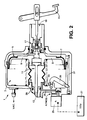
- the servo units illustrated in Figs. 1 to 5 of the accompanying drawings comprise a housing 1 which is divided internally into a vacuum pressure chamber 3 and an atmospheric pressure chamber 5 by a flexible diaphragm 7.
- the diaphragm 7 includes a power piston 9 which is connected in an actuator rod assembly 11.
- the actuator rod assembly 11 extends through the housing 1 and projects from either side, one end region 13 being connected to a master cylinder (not shown) and the other end region being connected to a brake pedal 15.
- a valve assembly 17 controls the flow of air to the atmospheric pressure chamber 5, air normally entering the unit via inlet 19.
- This valve assembly 17 incorporates a key arrangement 21 as disclosed in our Spanish Patent Application No.
- the key arrrangement 21 limiting the available movement of a valve control piston 23 relative to the servo housing 1 and resulting in a balanced condition when the brakes are released and the servo unit is at rest, this balanced condition providing for the immediate response of the servo unit as soon as the brake pedal 15 is moved to apply the brakes.
- a solenoid valve 25 is provided in the wall of the housing 1, the solenoid valve 25 being controlled by an electronic control unit 27 which monitors speed and torque at the vehicle wheels.
- the solenoid valve opens a passage 26 between the vacuum pressure chamber 3 and an axially flexible passage member 29 which extends from the power piston 9 to the wall of the housing, across the vacuum pressure chamber 3 and around the actuator rod assembly 11.
- the solenoid valve 25 closes the passage 26 to the vacuum pressure chamber 3, and opens the passage 26 to the atmosphere.
- atmospheric pressure is fed to the axially flexible passage member 29.
- a bypass 35 incorporating a one-way valve 33, extends from the solenoid valve 25 to the atmospheric pressure chamber 5 so that when traction control is required, the bypass 31 is opened to allow atmospheric pressure to be introduced into the atmospheric pressure chamber 5.
- the resulting initial movement of the diaphragm 7 and thus the power piston 9, upsets the balanced condition of valve assembly 17 so that the valve assembly 17 opens so as to allow air under atmospheric pressure to also flow from the axially flexible passage member 29 to the atmospheric pressure chamber 5 via the valve assembly 17, resulting in the brakes being actuated.
- the one-way valve 33 retains the pressure in the atmospheric pressure chamber 5 during normal braking when valve assembly 17 opens to allow air under atmospheric pressure to enter the atmospheric pressure chamber 5 via inlet 19.
- the bypass 31 is a pipe 35 which extends externally of the housing.
- the bypass 31 has a section 37 which extends through the wall of the housing 1, this section 37 being connected by a pipe 39 in the vacuum pressure chamber 3 to the one-way valve 33.
- the bypass 31 is formed by an axially flexible tube 41 which extends across the vacuum pressure chamber 3 from the diaphragm 7 to the wall of the housing 1 adjacent to the solenoid valve 25, the tube 41 flexing as the diaphragm 7 moves.
- the tube 41 connects, through the diaphragm 7, with the atmospheric pressure chamber 5.
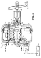
- FIG.4 A modified form of the embodiment of Fig.3 is shown in Fig.4, the housing 1 of the embodiment of Fig.4 being of a lightweight design and requiring axial tie bars 43 to strengthen its construction.
- One of these tie bars 43 extends through an axially flexible tube 41, the tube 41 connecting, through the diaphragm 7, with the atmospheric pressure chamber 5, and by a further pipe 45 with the one-way valve 33 and solenoid valve 25.
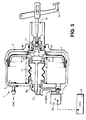
- FIG.5 of the accompanying drawings A still further embodiment of the present invention is shown in Fig.5 of the accompanying drawings, the bypass 35 being provided by passages 47 which extend through the power piston 9 connecting the flexible passage member 29 to the atmospheric pressure chamber 5.
- the solenoid valve 25 opens the flexible passage member 29 to the atmosphere so that atmospheric pressure immediately passes to the atmospheric pressure chamber 5 to actuate the servo unit and apply the brakes.
- the flexible passage member 29 is connected to the vacuum pressure chamber 3 via the solenoid valve 25, flap valves 49, i.e. the said one-way valve, being closed to prevent the chambers 3,5 from interconnecting.
- the present invention thus provides a servo unit with immediate response for normal braking, and with a traction control facility.
Landscapes
- Engineering & Computer Science (AREA)
- Transportation (AREA)
- Mechanical Engineering (AREA)
- Physics & Mathematics (AREA)
- Fluid Mechanics (AREA)
- Braking Systems And Boosters (AREA)
- Regulating Braking Force (AREA)
Description
- The present invention relates to a vacuum servo unit for use in a vehicle braking system.
- In particular the present invention relates to a servo unit of the type comprising a housing, the interior of which housing is divided into two chambers by a flexible diaphragm, one chamber being connectible to the exhaust manifold of an engine and thus then being subjected to a vacuum pressure, while the other chamber is connectible via a valve assembly to atmospheric pressure, so that the pressure difference across the diaphragm aids axial movement of a brake actuator rod assembly which extends through the housing and is connected to the diaphragm and to a master cylinder and brake pedal.
- More particularly, the present invention relates to a servo unit of the above-described type wherein a key arrangement limits the movement of a control piston of the valve assembly relative to a power piston which is connected to the diaphragm. Such a construction is disclosed in our Spanish Patent Application No. 551919. By virtue of this arrangement a balance is achieved in the rest position of the servo unit, i.e. with the brakes released, such that any movement of the actuator rod assembly in the brake applying direction will immediately cause the valve assembly to introduce atmospheric pressure and actuate the servo unit.
- Should such a servo unit be required to be used in a traction control system such as disclosed in our European Patent Application No.88307406.4, bearing in mind its immediate response advantage, this would not be possible as the introduction of atmospheric pressure via a solenoid valve and the valve assembly would not actuate the servo unit in view of the balanced condition of the valve assembly, the balanced condition precluding the provision of an air flow path through the valve assembly.
- The present invention thus aims to modify the above balanced type of servo unit for advantageous immediate response use in a traction control system.
- According to the present invention there is provided a servo unit for use in a vehicle braking system, the servo unit comprising a housing within which a flexible diaphragm separates a vacuum pressure chamber from an atmospheric pressure chamber, an actuator rod assembly extending through the housing and including a valve assembly having a valve control piston which has a laterally extending key, the key being engageable with a fixed stop in the housing to limit the movement of the valve control piston and cause a balance in the valve assembly between the vacuum and atmospheric pressure, a solenoid valve being controllable to either connect a flexible passage member extending around the actuator rod assembly across the vacuum pressure chamber between the housing and the diaphragm in the region of the valve assembly, to said vacuum pressure chamber, or to connect both said flexible passage member and a bypass leading from the solenoid valve to said atmospheric pressure chamber, to the atmosphere, said bypass incorporating a one-way valve.
- The provision of the bypass thus enables the atmospheric pressure chamber to be immediately connected to atmospheric pressure as and when traction control is required, whilst allowing for the advantageous immediate response of the balanced valve facility produced by the lateral key design of the valve control piston.
- In one embodiment of the present invention the bypass is a pipe which extends externally of the housing. Aternatively the bypass may pass, at least partially, through the wall of the housing, or through the diaphragm within the flexible passage member. In a further embodiment an axially flexible tube extends between the diaphragm and a wall of the housing, across the vacuum pressure chamber, the tube connecting the solenoid valve with the atmospheric chamber of the housing. In a lightweight housing design which is strengthened by a number of axially extending tie bars, at least one tie bar extends through the axially flexible tube which is connected across the vacuum pressure chamber between the diaphragm and the wall of the housing. One end region of this flexible tube opens through the diaphragm into the atmospheric pressure chamber, whilst the other end region connects with the solenoid valve via a further pipe.
- The present invention will now be further described, by way of example, with reference to the accompanying drawings, in which:-
- Fig.1 is a cross-sectional view through one embodiment of the present invention;
- Fig.2 is a cross-sectional view through another embodiment of the present invention;
- Fig.3 is a cross-sectional view through a further embodiment of the present invention;
- Fig.4 is a cross-sectional view through a still further embodiment of the present invention; and
- Fig.5 is a cross-sectional view through a still further embodiment of the present invention.
- The servo units illustrated in Figs. 1 to 5 of the accompanying drawings comprise a housing 1 which is divided internally into a
vacuum pressure chamber 3 and anatmospheric pressure chamber 5 by aflexible diaphragm 7. Thediaphragm 7 includes apower piston 9 which is connected in anactuator rod assembly 11. Theactuator rod assembly 11 extends through the housing 1 and projects from either side, oneend region 13 being connected to a master cylinder (not shown) and the other end region being connected to abrake pedal 15. Avalve assembly 17 controls the flow of air to theatmospheric pressure chamber 5, air normally entering the unit viainlet 19. Thisvalve assembly 17 incorporates akey arrangement 21 as disclosed in our Spanish Patent Application No. 551919, thekey arrrangement 21 limiting the available movement of avalve control piston 23 relative to the servo housing 1 and resulting in a balanced condition when the brakes are released and the servo unit is at rest, this balanced condition providing for the immediate response of the servo unit as soon as thebrake pedal 15 is moved to apply the brakes. - To provide for traction control independent of normal braking via the
brake pedal 15, asolenoid valve 25 is provided in the wall of the housing 1, thesolenoid valve 25 being controlled by anelectronic control unit 27 which monitors speed and torque at the vehicle wheels. For normal braking the solenoid valve opens apassage 26 between thevacuum pressure chamber 3 and an axiallyflexible passage member 29 which extends from thepower piston 9 to the wall of the housing, across thevacuum pressure chamber 3 and around theactuator rod assembly 11. When traction control is required thesolenoid valve 25 closes thepassage 26 to thevacuum pressure chamber 3, and opens thepassage 26 to the atmosphere. Thus atmospheric pressure is fed to the axiallyflexible passage member 29. However, due to the balanced condition of thevalve assembly 17 this atmospheric pressure cannot pass to theatmospheric pressure chamber 5 as can occur in the servo unit of our European Patent Application No.88307406.4. To solve this situation abypass 35, incorporating a one-way valve 33, extends from thesolenoid valve 25 to theatmospheric pressure chamber 5 so that when traction control is required, thebypass 31 is opened to allow atmospheric pressure to be introduced into theatmospheric pressure chamber 5. The resulting initial movement of thediaphragm 7 and thus thepower piston 9, upsets the balanced condition ofvalve assembly 17 so that thevalve assembly 17 opens so as to allow air under atmospheric pressure to also flow from the axiallyflexible passage member 29 to theatmospheric pressure chamber 5 via thevalve assembly 17, resulting in the brakes being actuated. The one-way valve 33 retains the pressure in theatmospheric pressure chamber 5 during normal braking whenvalve assembly 17 opens to allow air under atmospheric pressure to enter theatmospheric pressure chamber 5 viainlet 19. - In Fig.1, the
bypass 31 is apipe 35 which extends externally of the housing. - In Fig.2, the
bypass 31 has asection 37 which extends through the wall of the housing 1, thissection 37 being connected by apipe 39 in thevacuum pressure chamber 3 to the one-way valve 33. - In Fig.3, the
bypass 31 is formed by an axiallyflexible tube 41 which extends across thevacuum pressure chamber 3 from thediaphragm 7 to the wall of the housing 1 adjacent to thesolenoid valve 25, thetube 41 flexing as thediaphragm 7 moves. Thetube 41 connects, through thediaphragm 7, with theatmospheric pressure chamber 5. - A modified form of the embodiment of Fig.3 is shown in Fig.4, the housing 1 of the embodiment of Fig.4 being of a lightweight design and requiring
axial tie bars 43 to strengthen its construction. One of thesetie bars 43 extends through an axiallyflexible tube 41, thetube 41 connecting, through thediaphragm 7, with theatmospheric pressure chamber 5, and by afurther pipe 45 with the one-way valve 33 andsolenoid valve 25. - A still further embodiment of the present invention is shown in Fig.5 of the accompanying drawings, the
bypass 35 being provided bypassages 47 which extend through thepower piston 9 connecting theflexible passage member 29 to theatmospheric pressure chamber 5. Thus, when traction control is required, thesolenoid valve 25 opens theflexible passage member 29 to the atmosphere so that atmospheric pressure immediately passes to theatmospheric pressure chamber 5 to actuate the servo unit and apply the brakes. For normal braking theflexible passage member 29 is connected to thevacuum pressure chamber 3 via thesolenoid valve 25,flap valves 49, i.e. the said one-way valve, being closed to prevent thechambers - The present invention thus provides a servo unit with immediate response for normal braking, and with a traction control facility.
Claims (6)
- A servo unit for use in a vehicle braking system, the servo unit comprising a housing (1) within which a flexible diaphragm (7) separates a vacuum pressure chamber (3) from an atmospheric pressure chamber (5), an actuator rod assembly (11) extending through the housing (1) and including a valve assembly (17) having a valve control piston (23) which has a laterally extending key (21), the key (21) being engageable with a fixed stop in the housing to limit the movement of the valve control piston (23) and cause a balance in the valve assembly (17) between the vacuum and atmospheric pressure, characterised in that a solenoid valve (25) is controllable to either connect a flexible passage member (29) extending around the actuator rod assembly (11) across the vacuum pressure chamber (3) between the housing and the diaphragm (7) in the region of the valve assembly (17), to said vacuum pressure chamber (3), or to connect both said flexible passage member (29) and a bypass (31; 37,39; 35, 41,45; 47) leading from the solenoid valve (25) to said atmospheric pressure chamber (5), to the atmosphere, said bypass incorporating a one-way valve (33;49).
- A servo unit as claimed in claim 1, wherein the bypass (31) is formed by a pipe (35) which extends at least in part externally of the housing (1).
- A servo unit as claimed in claim 1, wherein the bypass (37,39) extends, at least partially (37) through a wall of the housing (1).
- A servo unit as claimed in claim 1, wherein the bypass (47) extends through the diaphragm (7) in the region within the flexible passage member (29).
- A servo unit as claimed in claim 1, wherein the bypass (35) is formed by an axially flexible tube (41) which extends between the diaphragm (7) and a wall of the housing (1) across the vacuum pressure chamber (3), the tube (41) connecting the solenoid valve (25) with the atmospheric chamber (5) of the housing (1).
- A servo unit as claimed in claim 1, wherein at least one tie bar (43) extends across the housing (1) through the diaphragm (7), the bypass (41,45) being formed by an axially flexible hollow tube (41) through which a tie bar extends, the tube (41) being connected across the vacuum pressure chamber (3) between the diaphragm (7) and a wall of the housing (1), one end region of the tube (41) communicating with the atmospheric pressure chamber (5) through the diaphragm (7), whilst the other end region of the tube (41) communicates with the solenoid valve (25) via a further pipe (45).
Applications Claiming Priority (2)
| Application Number | Priority Date | Filing Date | Title |
|---|---|---|---|
| GB8920588 | 1989-09-12 | ||
| GB898920588A GB8920588D0 (en) | 1989-09-12 | 1989-09-12 | Improvements relating to a vacuum servo unit for use in traction control |
Publications (3)
| Publication Number | Publication Date |
|---|---|
| EP0417945A2 EP0417945A2 (en) | 1991-03-20 |
| EP0417945A3 EP0417945A3 (en) | 1991-04-24 |
| EP0417945B1 true EP0417945B1 (en) | 1994-01-26 |
Family
ID=10662929
Family Applications (1)
| Application Number | Title | Priority Date | Filing Date |
|---|---|---|---|
| EP90309561A Expired - Lifetime EP0417945B1 (en) | 1989-09-12 | 1990-08-31 | Improvements relating to a vacuum servo unit for use in traction control |
Country Status (9)
| Country | Link |
|---|---|
| US (1) | US5176433A (en) |
| EP (1) | EP0417945B1 (en) |
| JP (1) | JPH03143763A (en) |
| KR (1) | KR970001505B1 (en) |
| BR (1) | BR9004530A (en) |
| CZ (1) | CZ279831B6 (en) |
| DE (1) | DE69006300T2 (en) |
| ES (1) | ES2050962T3 (en) |
| GB (1) | GB8920588D0 (en) |
Cited By (1)
| Publication number | Priority date | Publication date | Assignee | Title |
|---|---|---|---|---|
| WO2009003759A2 (en) | 2007-07-04 | 2009-01-08 | Continental Teves Ag & Co. Ohg | Servo brake |
Families Citing this family (19)
| Publication number | Priority date | Publication date | Assignee | Title |
|---|---|---|---|---|
| GB8920588D0 (en) * | 1989-09-12 | 1989-10-25 | Lucas Ind Plc | Improvements relating to a vacuum servo unit for use in traction control |
| FR2681826B1 (en) * | 1991-09-30 | 1993-11-26 | Bendix Europe Services Technique | MODULATED REACTION BRAKE ASSIST MOTOR. |
| JPH05221303A (en) * | 1992-02-17 | 1993-08-31 | Mazda Motor Corp | Vehicle slip control device |
| DE4227286C2 (en) * | 1992-08-18 | 1996-08-29 | Lucas Ind Plc | Pneumatic brake booster, in particular for motor vehicles |
| US5312173A (en) * | 1993-05-28 | 1994-05-17 | Alliedsignal Inc. | Control valve actuator |
| JPH09502942A (en) * | 1993-07-27 | 1997-03-25 | ルーカス・インダストリーズ・パブリック・リミテッド・カンパニー | Automotive braking system with electronically controlled brake booster |
| DE4400688C2 (en) * | 1993-07-27 | 1998-10-15 | Lucas Ind Plc | Vehicle brake system with an electronically controlled amplifier |
| US5388897A (en) * | 1993-08-23 | 1995-02-14 | Alliedsignal Inc. | Vacuum brake booster with traction control |
| US5338107A (en) * | 1993-11-03 | 1994-08-16 | Alliedsignal Inc. | Control valve actuator |
| US5357846A (en) * | 1993-11-24 | 1994-10-25 | Alliedsignal Inc. | Tandem brake booster |
| DE4418444C2 (en) * | 1994-05-26 | 1999-01-14 | Lucas Ind Plc | Electronically controllable brake booster for a vehicle brake system |
| JPH11278234A (en) * | 1998-03-31 | 1999-10-12 | Tokico Ltd | Braking force control device |
| KR100430548B1 (en) * | 2002-01-02 | 2004-05-10 | 엘지전자 주식회사 | System and method for controlling automatically an offset and an input gain of a projector |
| US6748846B2 (en) | 2002-02-15 | 2004-06-15 | Delphi Technologies, Inc. | Solenoid valve, vacuum booster diaphragm subassembly, and vacuum booster assembly |
| US6955044B1 (en) | 2004-08-19 | 2005-10-18 | Robert Bosch Gmbh | Reaction arrangement for brake booster |
| DE102006016545B3 (en) * | 2006-04-07 | 2007-05-16 | Lucas Automotive Gmbh | Braking force boosting device for vehicle brake system, has chamber arrangement with vacuum chamber and operating chamber that is separated over barrier, and damping units engaged at spring, where units are attached at clamping bolt |
| US8070239B2 (en) * | 2007-01-20 | 2011-12-06 | Nissan Motor Co., Ltd. | Regenerative braking coordination device |
| EP2117894B1 (en) | 2007-02-03 | 2018-10-10 | Continental Teves AG & Co. OHG | Servo brake |
| FR2945502A1 (en) * | 2009-05-18 | 2010-11-19 | Bosch Gmbh Robert | SERVOFREIN WITH ELECTROVALVE |
Family Cites Families (18)
| Publication number | Priority date | Publication date | Assignee | Title |
|---|---|---|---|---|
| JPS56102009A (en) * | 1980-01-21 | 1981-08-15 | Toyo Ink Mfg Co | Insulated wire |
| JPS59145652A (en) * | 1983-02-10 | 1984-08-21 | Mitsubishi Motors Corp | Antislip apparatus |
| JPS60157951A (en) * | 1984-01-28 | 1985-08-19 | Tokico Ltd | Brake apparatus for car |
| FR2569246B1 (en) * | 1984-08-16 | 1986-12-05 | Bendix France | STOP KEY FOR A VALVE DIVER OF A BRAKE ASSISTANCE SERVOMOTOR, AND SERVOMOTOR EQUIPPED WITH SUCH A KEY |
| US4871215A (en) * | 1984-08-20 | 1989-10-03 | Tokico Ltd. | Vehicle braking system |
| US4667471A (en) * | 1984-08-20 | 1987-05-26 | Allied Corporation | Brake booster for vehicular hill holder system |
| US4800799A (en) * | 1985-03-05 | 1989-01-31 | Aisin Seiki Kabushiki Kaisha | Vacuum type brake booster |
| ES551919A0 (en) * | 1986-02-12 | 1986-12-01 | Lucas Ind Plc | IMPROVEMENTS INTRODUCED IN THE SERVO-BRAKE CONTROL MEDIA FOR VEHICLES |
| DE3705333A1 (en) * | 1986-02-20 | 1987-08-27 | Tokico Ltd | BRAKE DEVICE FOR MOTOR VEHICLES |
| FR2598992B1 (en) * | 1986-05-26 | 1992-04-03 | Jidosha Kiki Co | VEHICLE SERVO BRAKE |
| JPS6358062U (en) * | 1986-10-06 | 1988-04-18 | ||
| US4778225A (en) * | 1987-08-10 | 1988-10-18 | Allied-Signal Inc. | Brake vacuum modulator traction control with pressure source variable as function of engine load during incipient wheel spin conditions |
| GB8719299D0 (en) * | 1987-08-14 | 1987-09-23 | Lucas Ind Plc | Traction control system |
| GB8802297D0 (en) * | 1988-02-02 | 1988-03-02 | Lucas Ind Plc | Brake servo booster |
| DE3820657A1 (en) * | 1988-06-18 | 1989-12-21 | Bosch Gmbh Robert | VACUUM MOTOR FOR BRAKE SYSTEMS IN VEHICLES |
| JPH0212255A (en) * | 1988-06-30 | 1990-01-17 | Konica Corp | Colored image transfer material |
| GB8920588D0 (en) * | 1989-09-12 | 1989-10-25 | Lucas Ind Plc | Improvements relating to a vacuum servo unit for use in traction control |
| IN176847B (en) * | 1989-01-18 | 1996-09-21 | Lucas Ind Plc |
-
1989
- 1989-09-12 GB GB898920588A patent/GB8920588D0/en active Pending
-
1990
- 1990-08-31 EP EP90309561A patent/EP0417945B1/en not_active Expired - Lifetime
- 1990-08-31 DE DE90309561T patent/DE69006300T2/en not_active Expired - Fee Related
- 1990-08-31 ES ES90309561T patent/ES2050962T3/en not_active Expired - Lifetime
- 1990-09-10 KR KR1019900014286A patent/KR970001505B1/en not_active Expired - Fee Related
- 1990-09-11 BR BR909004530A patent/BR9004530A/en not_active IP Right Cessation
- 1990-09-12 CZ CS904445A patent/CZ279831B6/en not_active IP Right Cessation
- 1990-09-12 US US07/587,931 patent/US5176433A/en not_active Expired - Fee Related
- 1990-09-12 JP JP2242294A patent/JPH03143763A/en active Pending
Cited By (2)
| Publication number | Priority date | Publication date | Assignee | Title |
|---|---|---|---|---|
| WO2009003759A2 (en) | 2007-07-04 | 2009-01-08 | Continental Teves Ag & Co. Ohg | Servo brake |
| DE102007044423A1 (en) | 2007-07-04 | 2009-01-15 | Continental Teves Ag & Co. Ohg | Brake booster |
Also Published As
| Publication number | Publication date |
|---|---|
| DE69006300T2 (en) | 1994-05-05 |
| ES2050962T3 (en) | 1994-06-01 |
| DE69006300D1 (en) | 1994-03-10 |
| GB8920588D0 (en) | 1989-10-25 |
| EP0417945A3 (en) | 1991-04-24 |
| US5176433A (en) | 1993-01-05 |
| BR9004530A (en) | 1991-09-10 |
| JPH03143763A (en) | 1991-06-19 |
| EP0417945A2 (en) | 1991-03-20 |
| CZ279831B6 (en) | 1995-07-12 |
| KR970001505B1 (en) | 1997-02-11 |
| KR910006094A (en) | 1991-04-27 |
| CS444590A3 (en) | 1992-02-19 |
Similar Documents
| Publication | Publication Date | Title |
|---|---|---|
| EP0417945A2 (en) | Improvements relating to a vacuum servo unit for use in traction control | |
| US6033036A (en) | Electronically controllable brake operating system for motor vehicles | |
| US5758930A (en) | Electronically controllable brake actuation system | |
| EP1802503B1 (en) | Brake system for motor vehicles | |
| DE3428869A1 (en) | BRAKE-SLIP-CONTROLLED BRAKE SYSTEM | |
| US6626505B2 (en) | Braking pressure modulator for an electronic braking system | |
| US6467854B2 (en) | Braking pressure modulator for a trailer with electronic braking system | |
| CZ268696A3 (en) | Hydraulic braking device for motor vehicles | |
| US4932727A (en) | Automotive vehicle brake system | |
| WO1996020102A1 (en) | Hydraulic braking system for motor vehicles | |
| KR20000075882A (en) | Hydraulic vehicle brake system | |
| CZ20031472A3 (en) | Method for controlling electrohydraulic brake system | |
| US20080265665A1 (en) | Brake System for Motor Vehicles | |
| US6547342B1 (en) | Actuator unit for an electronically controlled vehicle brake system | |
| JPS62168752A (en) | Slip control hydraulic servo brake system | |
| US4979426A (en) | Vacuum brake power booster | |
| JP2848851B2 (en) | Bakium booster for brake device in vehicle | |
| DE3817785A1 (en) | MOTOR VEHICLE BRAKE SYSTEM | |
| JPS6366702B2 (en) | ||
| US4693521A (en) | Automobile braking force control apparatus | |
| DE3813173A1 (en) | METHOD FOR OPERATING A MASTER CYLINDER | |
| US20060076829A1 (en) | Vehicle brake system equipped with a friction brake and a regenerative brake | |
| DE4028925A1 (en) | Servo for hydraulic brakes - has servo membrane uncoupled from reaction element on master cylinder to isolate brake pedal during ABS | |
| EP0427787B1 (en) | Three-channel adaptive braking system | |
| US5005918A (en) | Automotive vehicle brake system |
Legal Events
| Date | Code | Title | Description |
|---|---|---|---|
| PUAI | Public reference made under article 153(3) epc to a published international application that has entered the european phase |
Free format text: ORIGINAL CODE: 0009012 |
|
| PUAL | Search report despatched |
Free format text: ORIGINAL CODE: 0009013 |
|
| AK | Designated contracting states |
Kind code of ref document: A2 Designated state(s): DE ES FR GB IT |
|
| AK | Designated contracting states |
Kind code of ref document: A3 Designated state(s): DE ES FR GB IT |
|
| 17P | Request for examination filed |
Effective date: 19911017 |
|
| 17Q | First examination report despatched |
Effective date: 19921027 |
|
| GRAA | (expected) grant |
Free format text: ORIGINAL CODE: 0009210 |
|
| AK | Designated contracting states |
Kind code of ref document: B1 Designated state(s): DE ES FR GB IT |
|
| ITF | It: translation for a ep patent filed | ||
| REF | Corresponds to: |
Ref document number: 69006300 Country of ref document: DE Date of ref document: 19940310 |
|
| ET | Fr: translation filed | ||
| REG | Reference to a national code |
Ref country code: ES Ref legal event code: FG2A Ref document number: 2050962 Country of ref document: ES Kind code of ref document: T3 |
|
| PLBE | No opposition filed within time limit |
Free format text: ORIGINAL CODE: 0009261 |
|
| STAA | Information on the status of an ep patent application or granted ep patent |
Free format text: STATUS: NO OPPOSITION FILED WITHIN TIME LIMIT |
|
| 26N | No opposition filed | ||
| PGFP | Annual fee paid to national office [announced via postgrant information from national office to epo] |
Ref country code: GB Payment date: 20010629 Year of fee payment: 12 |
|
| PGFP | Annual fee paid to national office [announced via postgrant information from national office to epo] |
Ref country code: FR Payment date: 20010802 Year of fee payment: 12 |
|
| PGFP | Annual fee paid to national office [announced via postgrant information from national office to epo] |
Ref country code: ES Payment date: 20010814 Year of fee payment: 12 |
|
| PGFP | Annual fee paid to national office [announced via postgrant information from national office to epo] |
Ref country code: DE Payment date: 20010831 Year of fee payment: 12 |
|
| REG | Reference to a national code |
Ref country code: GB Ref legal event code: IF02 |
|
| PG25 | Lapsed in a contracting state [announced via postgrant information from national office to epo] |
Ref country code: GB Free format text: LAPSE BECAUSE OF NON-PAYMENT OF DUE FEES Effective date: 20020831 |
|
| PG25 | Lapsed in a contracting state [announced via postgrant information from national office to epo] |
Ref country code: ES Free format text: LAPSE BECAUSE OF NON-PAYMENT OF DUE FEES Effective date: 20020901 |
|
| PG25 | Lapsed in a contracting state [announced via postgrant information from national office to epo] |
Ref country code: DE Free format text: LAPSE BECAUSE OF NON-PAYMENT OF DUE FEES Effective date: 20030301 |
|
| GBPC | Gb: european patent ceased through non-payment of renewal fee |
Effective date: 20020831 |
|
| PG25 | Lapsed in a contracting state [announced via postgrant information from national office to epo] |
Ref country code: FR Free format text: LAPSE BECAUSE OF NON-PAYMENT OF DUE FEES Effective date: 20030430 |
|
| REG | Reference to a national code |
Ref country code: FR Ref legal event code: ST |
|
| REG | Reference to a national code |
Ref country code: ES Ref legal event code: FD2A Effective date: 20030912 |
|
| PG25 | Lapsed in a contracting state [announced via postgrant information from national office to epo] |
Ref country code: IT Free format text: LAPSE BECAUSE OF NON-PAYMENT OF DUE FEES;WARNING: LAPSES OF ITALIAN PATENTS WITH EFFECTIVE DATE BEFORE 2007 MAY HAVE OCCURRED AT ANY TIME BEFORE 2007. THE CORRECT EFFECTIVE DATE MAY BE DIFFERENT FROM THE ONE RECORDED. Effective date: 20050831 |