EP0419735A1 - Support pour rouleaux de papier - Google Patents
Support pour rouleaux de papier Download PDFInfo
- Publication number
- EP0419735A1 EP0419735A1 EP89202427A EP89202427A EP0419735A1 EP 0419735 A1 EP0419735 A1 EP 0419735A1 EP 89202427 A EP89202427 A EP 89202427A EP 89202427 A EP89202427 A EP 89202427A EP 0419735 A1 EP0419735 A1 EP 0419735A1
- Authority
- EP
- European Patent Office
- Prior art keywords
- frame
- holder
- holder according
- support element
- parts
- Prior art date
- Legal status (The legal status is an assumption and is not a legal conclusion. Google has not performed a legal analysis and makes no representation as to the accuracy of the status listed.)
- Granted
Links
- 238000001746 injection moulding Methods 0.000 claims 1
- 230000004323 axial length Effects 0.000 abstract 1
- 238000000034 method Methods 0.000 description 2
- 238000004806 packaging method and process Methods 0.000 description 2
- 230000000717 retained effect Effects 0.000 description 2
- 230000000694 effects Effects 0.000 description 1
- 230000002349 favourable effect Effects 0.000 description 1
Images

Classifications
-
- B—PERFORMING OPERATIONS; TRANSPORTING
- B65—CONVEYING; PACKING; STORING; HANDLING THIN OR FILAMENTARY MATERIAL
- B65H—HANDLING THIN OR FILAMENTARY MATERIAL, e.g. SHEETS, WEBS, CABLES
- B65H35/00—Delivering articles from cutting or line-perforating machines; Article or web delivery apparatus incorporating cutting or line-perforating devices, e.g. adhesive tape dispensers
- B65H35/0006—Article or web delivery apparatus incorporating cutting or line-perforating devices
- B65H35/002—Hand-held or table apparatus
Definitions
- the invention relates to a holder for one or more paper rolls, tape or the like, which holder consists of a frame, an axis carried by this frame for a roll and, if necessary, a knife strip carried by this frame.
- Such holders are often used in shops, and there is a need to use the holder for rolls of paper of various types. Depending on the season, it may happen that a roll of paper with a Christmas print, for example, should be temporarily suspended in the holder, while the roll of packaging paper should also be retained for normal purposes.
- the holder can be made suitable for holding rolls of packaging tape and the like.
- the invention aims to provide a holder that is so universal that all of these applications can be carried out.
- the holder according to the invention is characterized in that there is in each case an element supporting the axle end, which can be removed from and fixed to the frame and which is provided with a guide element, in such a way that, when the element is mounted, this guide element has an inclination towards the knife strip .
- the removable element can be attached at various points in the frame, whereby one or more rollers can be accommodated in the frame if desired.
- the frame preferably has two parallel rod-shaped profiles at least at a distance from one another for receiving the support elements.
- the user can easily move the support elements along the profiles after removal, which means that more rollers can be attached in a simple manner.
- the support element may be preferable to have the support element with a cavity opening to one side equip to accommodate the axle end.
- the support element is also suitable for the assembly of a fixed axis, for example for reels.
- the element is designed as a flat plate with at least one upstanding rib as a guide element.
- This rib can also be provided with cam-shaped projections, which are used to implement the cavity for receiving the axle or to fasten the knife strip holder.
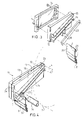
- the frame of the holder is indicated by number 1, which here has a rectangular shape and is provided with two support feet 2, which have been attached in such a way that the parallel rod-shaped frame parts 3 are perpendicular or almost perpendicular.
- An axis 4 is received between the frame parts 3, for either a series of spools 5 for tapes or the like or for a small reel 6, around a large reel 7.
- the ends 4 are each supported at their ends by an element which can be attached to or removed from the upright rod-shaped frame parts 3 in order to adjust their height depending on the thickness of the paper roll 6, 7 or on the diameter of the spools 5.
- the axis 4 for the spools 5 for the tapes need not experience any change in position relative to the frame 1, which is probably the case for the axes 4 of the rollers 6 and 7, respectively, because when the paper is removed from one such a roll, the roll diameter will become smaller and it is preferable to hold the rolls against a tear-off knife 8 belonging to the roll.
- This knife is fastened in a carrier 9, which is also received at the ends between the elements according to one of FIGS. 2-4, which will be explained in more detail below.
- each support element 10 consists of two shell-shaped parts 11, 12.
- the shell-shaped parts have a recess 13 on the side facing one another, in such a way that the space in between is somewhat smaller than the thickness of the frame parts 3.
- the elements 11, 12 are fastened to one another with a screw-nut connection 14, so that the two shell-shaped parts 11, 12 can be firmly clamped to the rod-shaped frame parts 3 by tightening the screw 14.
- One of the shells 12 has, on the side facing away from the recess 13, two parallel ribs 15, 16, each of which is provided with a cam-shaped part 17 pointing outwards at its ends.
- the rib 16 is also equipped with two cams 18 near its center, which extend parallel to one another and form an upwardly opening cavity 19.
- the assembly of the shell-shaped parts 11, 12 can be such that the cams 18 point upwards, as in FIG. 2, as a result of which this assembly method is suitable for accommodating an axis 4 for the tape reels 5.
- the end of the axis 4 must be attached between the cams 18, that is, in the cavity 19.
- the axis 4 can rotate freely, but is included in the axial sense and cannot move along the rib 16.
- FIG. 3 Another mounting method is shown in FIG. 3, the cams 18 pointing downwards and the rib 15 coming to rest on the top.
- the rib 15 has a downwardly sloping surface, in such a way that in the mounted state an axis 4 of a roller 6 or 7 follows along the rib 15 want to move down, namely to the knife holder 9 with cutting edge 8 stretched between the frame parts 3. In this way, a favorable cutting effect is exerted by the cutting edge 8 on a sheet of paper after tearing off after a sufficient length of the roll 6, 7 has been rolled off.
- the knife carrier 9 with the cutting edge 8 can also be fastened with an element 10 in that the knife carrier 1 is designed as a channel-shaped profile with a body plate part 20 and two folded-over flanges 21.
- the folding over of the flanges 21 is such that they grip around the cams 17 of the ribs 15, 16.
- the assembly is carried out by first bringing the cams 17 into the space under the flanges 21, after which the element part 12 is moved between the frame parts 3, then the plate 11 is attached and tightened with the corresponding screw connection 14. If desired, the screw connection 14 cannot be provided with loose nuts according to FIG. 2, but with a nut strip 22 which fits between the ribs 15, 16.
- FIG. 4 shows an alternative embodiment of the support element 10, the same reference numbers being retained in the figure for the same parts.
- the element is designed here with two parallel ribs 15, 16, the rib 16 not being equipped with the cams 18.
- the shell parts 11, 12 of the element 10 are connected at the rear end by means of a spring strip 23 in such a way that a hinge is created there.
- a clamping bolt 24 can be attached on the opposite side in order to clamp the parts 11, 12 onto one another, wherein the frame part 3 can be clamped in the cavity 13.
- the screw connection 24 can be equipped on the rib side of the shell element 12 with a round support cam 25 onto which the end of a support tube or rod 26 can be pushed.
- the cam 25 lies at some distance from the knife carrier 9 with the cutting edge 8, which can be fastened to the support element 10 in a corresponding manner in FIG. 2, so that a roller 7, which is shown with a broken line in FIG leans the freely rotatable rod 26 instead of against the knife carrier 9. This makes it easier to roll off heavy rolls beforehand.
- a sheet of paper is torn off in the same way as in FIG. 3.
- the shell part 12 need not be equipped with ribs, but can also be provided with similar recesses in the front surface thereof.
- the shell parts 12 can be fastened in any manner, it being noted that the shell part can be replaced by other clamping means which cooperate with the part 12.
Landscapes
- Unwinding Webs (AREA)
Priority Applications (3)
| Application Number | Priority Date | Filing Date | Title |
|---|---|---|---|
| EP89202427A EP0419735B1 (fr) | 1989-09-27 | 1989-09-27 | Support pour rouleaux de papier |
| AT89202427T ATE116941T1 (de) | 1989-09-27 | 1989-09-27 | Papierrollenhalterung. |
| DE58908887T DE58908887D1 (de) | 1989-09-27 | 1989-09-27 | Papierrollenhalterung. |
Applications Claiming Priority (1)
| Application Number | Priority Date | Filing Date | Title |
|---|---|---|---|
| EP89202427A EP0419735B1 (fr) | 1989-09-27 | 1989-09-27 | Support pour rouleaux de papier |
Publications (2)
| Publication Number | Publication Date |
|---|---|
| EP0419735A1 true EP0419735A1 (fr) | 1991-04-03 |
| EP0419735B1 EP0419735B1 (fr) | 1995-01-11 |
Family
ID=8202475
Family Applications (1)
| Application Number | Title | Priority Date | Filing Date |
|---|---|---|---|
| EP89202427A Expired - Lifetime EP0419735B1 (fr) | 1989-09-27 | 1989-09-27 | Support pour rouleaux de papier |
Country Status (3)
| Country | Link |
|---|---|
| EP (1) | EP0419735B1 (fr) |
| AT (1) | ATE116941T1 (fr) |
| DE (1) | DE58908887D1 (fr) |
Cited By (3)
| Publication number | Priority date | Publication date | Assignee | Title |
|---|---|---|---|---|
| EP0569641A1 (fr) * | 1992-05-14 | 1993-11-18 | Sonoco Products Company | Appareil de distribution pour sacs plastiques |
| EP1505027A1 (fr) * | 2003-08-08 | 2005-02-09 | Legro B.V. | Dispositif de rupture pour des matériaux en feuille avec dispositif de protection |
| NL1026445C2 (nl) * | 2004-06-17 | 2005-12-20 | Holding Aldipro B V | Inrichting voor het telkens afsnijden van een vel baanmateriaal. |
Citations (4)
| Publication number | Priority date | Publication date | Assignee | Title |
|---|---|---|---|---|
| CH142969A (fr) * | 1929-10-11 | 1930-10-31 | Beauverd & Metra Societe Anony | Appareil pour la fourniture d'au moins une bande de matiére. |
| CH404463A (de) * | 1963-11-27 | 1965-12-15 | Schmirler Otto | Abreissgerät für eine Rolle mit einer Bahn blatt- oder folienartigen Stoffes, insbesondere Papier |
| FR2346263A1 (fr) * | 1976-03-29 | 1977-10-28 | Zettwoog Daniel | Chevalet pour le stockage de rouleaux de produit en feuille |
| GB1538002A (en) * | 1977-05-04 | 1979-01-10 | Valero Frias E | Apparatus for supporting and exhibiting rolled-up sheet material |
-
1989
- 1989-09-27 EP EP89202427A patent/EP0419735B1/fr not_active Expired - Lifetime
- 1989-09-27 AT AT89202427T patent/ATE116941T1/de not_active IP Right Cessation
- 1989-09-27 DE DE58908887T patent/DE58908887D1/de not_active Expired - Lifetime
Patent Citations (4)
| Publication number | Priority date | Publication date | Assignee | Title |
|---|---|---|---|---|
| CH142969A (fr) * | 1929-10-11 | 1930-10-31 | Beauverd & Metra Societe Anony | Appareil pour la fourniture d'au moins une bande de matiére. |
| CH404463A (de) * | 1963-11-27 | 1965-12-15 | Schmirler Otto | Abreissgerät für eine Rolle mit einer Bahn blatt- oder folienartigen Stoffes, insbesondere Papier |
| FR2346263A1 (fr) * | 1976-03-29 | 1977-10-28 | Zettwoog Daniel | Chevalet pour le stockage de rouleaux de produit en feuille |
| GB1538002A (en) * | 1977-05-04 | 1979-01-10 | Valero Frias E | Apparatus for supporting and exhibiting rolled-up sheet material |
Cited By (4)
| Publication number | Priority date | Publication date | Assignee | Title |
|---|---|---|---|---|
| EP0569641A1 (fr) * | 1992-05-14 | 1993-11-18 | Sonoco Products Company | Appareil de distribution pour sacs plastiques |
| EP1505027A1 (fr) * | 2003-08-08 | 2005-02-09 | Legro B.V. | Dispositif de rupture pour des matériaux en feuille avec dispositif de protection |
| NL1026445C2 (nl) * | 2004-06-17 | 2005-12-20 | Holding Aldipro B V | Inrichting voor het telkens afsnijden van een vel baanmateriaal. |
| EP1630117A3 (fr) * | 2004-06-17 | 2008-09-17 | Holding Aldipro B.V. | Dispositif de coupe d'une ou de plusieurs feuilles de matériau à la fois |
Also Published As
| Publication number | Publication date |
|---|---|
| EP0419735B1 (fr) | 1995-01-11 |
| DE58908887D1 (de) | 1995-02-23 |
| ATE116941T1 (de) | 1995-01-15 |
Similar Documents
| Publication | Publication Date | Title |
|---|---|---|
| DE9420475U1 (de) | Vorrichtung zum Befestigen von Dachdichtungs- und Isoliermaterial auf Flachdächern | |
| DE3728392C2 (fr) | ||
| DE2060595C3 (de) | Klemmvorrichtung zum Verbinden zweier Rohre | |
| DE2817783C2 (de) | Einrichtung zum Ausbreiten von zylindrischen Rollen | |
| EP0419735B1 (fr) | Support pour rouleaux de papier | |
| DE1755273C3 (de) | Abschließbarer Skitrager für Kraftfahrzeuge | |
| DE3049323C2 (de) | Vorrichtung zum Abrollen und Trennen von Materialbahnen | |
| DE4118893A1 (de) | Halter fuer balkonblumenkaesten | |
| DE8534636U1 (de) | Vorrichtung zur Befestigung von Dachlasten | |
| EP0172555B1 (fr) | Vice | |
| DE2834474C3 (de) | Vorrichtung zum Lagern von Instrumenten | |
| DE8907328U1 (de) | Papierrollenhalterung | |
| EP0485886B1 (fr) | Utilisation d'un dispositif destiné à recevoir des bobines | |
| DE2758563A1 (de) | Vorrichtung zum zuschneiden von tapetenbahnen u.dgl. | |
| DE3534664A1 (de) | Etikettenbehaelter fuer etikettiermaschinen | |
| DE1102334B (de) | Vorrichtung zur Herstellung von Zierschleifen aus gewickelten und in Laengsrichtung flach gefalteten Bandwickeln | |
| DE69003707T2 (de) | Mehrzweckwandhalter für Behälter. | |
| DE3637002A1 (de) | Skispanner | |
| DE2513955C3 (de) | Bettuchhalter | |
| DE7739937U1 (de) | Vorrichtung zum zuschneiden von tapetenbahnen u.dgl. | |
| DE75581C (de) | Vorrichtung zum We nden von Säcken von Hand | |
| DE68903014T2 (de) | Vorrichtung zur zusammenfuegung der enden eines breiten bandes unter spannung zur ueberziehung einer flaeche, insbesondere einer papiermaschinenrolle. | |
| DE2424360A1 (de) | Vorrichtung zum vereinzeln von zeitungsbeilagen | |
| DE2630451C3 (fr) | ||
| DE3028265A1 (de) | Klemmvorrichtung |
Legal Events
| Date | Code | Title | Description |
|---|---|---|---|
| PUAI | Public reference made under article 153(3) epc to a published international application that has entered the european phase |
Free format text: ORIGINAL CODE: 0009012 |
|
| AK | Designated contracting states |
Kind code of ref document: A1 Designated state(s): AT BE CH DE GB LI NL |
|
| 17P | Request for examination filed |
Effective date: 19910920 |
|
| 17Q | First examination report despatched |
Effective date: 19930408 |
|
| GRAA | (expected) grant |
Free format text: ORIGINAL CODE: 0009210 |
|
| AK | Designated contracting states |
Kind code of ref document: B1 Designated state(s): AT BE CH DE GB LI NL |
|
| REF | Corresponds to: |
Ref document number: 116941 Country of ref document: AT Date of ref document: 19950115 Kind code of ref document: T |
|
| REF | Corresponds to: |
Ref document number: 58908887 Country of ref document: DE Date of ref document: 19950223 |
|
| GBT | Gb: translation of ep patent filed (gb section 77(6)(a)/1977) |
Effective date: 19950215 |
|
| PLBE | No opposition filed within time limit |
Free format text: ORIGINAL CODE: 0009261 |
|
| STAA | Information on the status of an ep patent application or granted ep patent |
Free format text: STATUS: NO OPPOSITION FILED WITHIN TIME LIMIT |
|
| 26N | No opposition filed | ||
| REG | Reference to a national code |
Ref country code: GB Ref legal event code: IF02 |
|
| PGFP | Annual fee paid to national office [announced via postgrant information from national office to epo] |
Ref country code: NL Payment date: 20081231 Year of fee payment: 20 Ref country code: CH Payment date: 20081223 Year of fee payment: 20 |
|
| PGFP | Annual fee paid to national office [announced via postgrant information from national office to epo] |
Ref country code: AT Payment date: 20081222 Year of fee payment: 20 |
|
| PGFP | Annual fee paid to national office [announced via postgrant information from national office to epo] |
Ref country code: BE Payment date: 20081223 Year of fee payment: 20 |
|
| PGFP | Annual fee paid to national office [announced via postgrant information from national office to epo] |
Ref country code: DE Payment date: 20081230 Year of fee payment: 20 |
|
| PGFP | Annual fee paid to national office [announced via postgrant information from national office to epo] |
Ref country code: GB Payment date: 20081224 Year of fee payment: 20 |
|
| BE20 | Be: patent expired |
Owner name: *SCHON B.V. Effective date: 20090927 |
|
| REG | Reference to a national code |
Ref country code: CH Ref legal event code: PL |
|
| REG | Reference to a national code |
Ref country code: GB Ref legal event code: PE20 Expiry date: 20090926 |
|
| PG25 | Lapsed in a contracting state [announced via postgrant information from national office to epo] |
Ref country code: GB Free format text: LAPSE BECAUSE OF EXPIRATION OF PROTECTION Effective date: 20090926 Ref country code: NL Free format text: LAPSE BECAUSE OF EXPIRATION OF PROTECTION Effective date: 20090927 |
|
| NLV7 | Nl: ceased due to reaching the maximum lifetime of a patent |