EP0420243A1 - Keramische Statorschaufel - Google Patents
Keramische Statorschaufel Download PDFInfo
- Publication number
- EP0420243A1 EP0420243A1 EP19900118573 EP90118573A EP0420243A1 EP 0420243 A1 EP0420243 A1 EP 0420243A1 EP 19900118573 EP19900118573 EP 19900118573 EP 90118573 A EP90118573 A EP 90118573A EP 0420243 A1 EP0420243 A1 EP 0420243A1
- Authority
- EP
- European Patent Office
- Prior art keywords
- blade
- disposed
- insulating plate
- axis
- heat
- Prior art date
- Legal status (The legal status is an assumption and is not a legal conclusion. Google has not performed a legal analysis and makes no representation as to the accuracy of the status listed.)
- Withdrawn
Links
- 239000000919 ceramic Substances 0.000 title claims abstract description 51
- 239000000567 combustion gas Substances 0.000 claims abstract description 19
- 229910010293 ceramic material Inorganic materials 0.000 claims abstract description 17
- 238000011144 upstream manufacturing Methods 0.000 claims abstract description 4
- 239000007789 gas Substances 0.000 claims description 26
- 238000001816 cooling Methods 0.000 claims description 8
- 239000002184 metal Substances 0.000 claims description 8
- 230000002093 peripheral effect Effects 0.000 claims description 4
- 238000010276 construction Methods 0.000 description 3
- 238000000465 moulding Methods 0.000 description 3
- 239000000835 fiber Substances 0.000 description 2
- 229910010272 inorganic material Inorganic materials 0.000 description 2
- 239000011147 inorganic material Substances 0.000 description 2
- HBMJWWWQQXIZIP-UHFFFAOYSA-N silicon carbide Chemical compound [Si+]#[C-] HBMJWWWQQXIZIP-UHFFFAOYSA-N 0.000 description 2
- 229910010271 silicon carbide Inorganic materials 0.000 description 2
- 229910052581 Si3N4 Inorganic materials 0.000 description 1
- PNEYBMLMFCGWSK-UHFFFAOYSA-N aluminium oxide Inorganic materials [O-2].[O-2].[O-2].[Al+3].[Al+3] PNEYBMLMFCGWSK-UHFFFAOYSA-N 0.000 description 1
- 239000000470 constituent Substances 0.000 description 1
- 230000000694 effects Effects 0.000 description 1
- 230000007613 environmental effect Effects 0.000 description 1
- 239000011256 inorganic filler Substances 0.000 description 1
- 229910003475 inorganic filler Inorganic materials 0.000 description 1
- 238000009413 insulation Methods 0.000 description 1
- 238000004519 manufacturing process Methods 0.000 description 1
- 239000000463 material Substances 0.000 description 1
- 239000007769 metal material Substances 0.000 description 1
- -1 silica compound Chemical class 0.000 description 1
- VYPSYNLAJGMNEJ-UHFFFAOYSA-N silicon dioxide Inorganic materials O=[Si]=O VYPSYNLAJGMNEJ-UHFFFAOYSA-N 0.000 description 1
- 239000000377 silicon dioxide Substances 0.000 description 1
- HQVNEWCFYHHQES-UHFFFAOYSA-N silicon nitride Chemical compound N12[Si]34N5[Si]62N3[Si]51N64 HQVNEWCFYHHQES-UHFFFAOYSA-N 0.000 description 1
- 229910001220 stainless steel Inorganic materials 0.000 description 1
- 239000010935 stainless steel Substances 0.000 description 1
- 230000008646 thermal stress Effects 0.000 description 1
- 239000002759 woven fabric Substances 0.000 description 1
Images


Classifications
-
- F—MECHANICAL ENGINEERING; LIGHTING; HEATING; WEAPONS; BLASTING
- F01—MACHINES OR ENGINES IN GENERAL; ENGINE PLANTS IN GENERAL; STEAM ENGINES
- F01D—NON-POSITIVE DISPLACEMENT MACHINES OR ENGINES, e.g. STEAM TURBINES
- F01D9/00—Stators
- F01D9/06—Fluid supply conduits to nozzles or the like
- F01D9/065—Fluid supply or removal conduits traversing the working fluid flow, e.g. for lubrication-, cooling-, or sealing fluids
-
- F—MECHANICAL ENGINEERING; LIGHTING; HEATING; WEAPONS; BLASTING
- F01—MACHINES OR ENGINES IN GENERAL; ENGINE PLANTS IN GENERAL; STEAM ENGINES
- F01D—NON-POSITIVE DISPLACEMENT MACHINES OR ENGINES, e.g. STEAM TURBINES
- F01D5/00—Blades; Blade-carrying members; Heating, heat-insulating, cooling or antivibration means on the blades or the members
- F01D5/30—Fixing blades to rotors; Blade roots ; Blade spacers
- F01D5/3084—Fixing blades to rotors; Blade roots ; Blade spacers the blades being made of ceramics
-
- F—MECHANICAL ENGINEERING; LIGHTING; HEATING; WEAPONS; BLASTING
- F01—MACHINES OR ENGINES IN GENERAL; ENGINE PLANTS IN GENERAL; STEAM ENGINES
- F01D—NON-POSITIVE DISPLACEMENT MACHINES OR ENGINES, e.g. STEAM TURBINES
- F01D9/00—Stators
- F01D9/02—Nozzles; Nozzle boxes; Stator blades; Guide conduits, e.g. individual nozzles
- F01D9/04—Nozzles; Nozzle boxes; Stator blades; Guide conduits, e.g. individual nozzles forming ring or sector
- F01D9/042—Nozzles; Nozzle boxes; Stator blades; Guide conduits, e.g. individual nozzles forming ring or sector fixing blades to stators
-
- F—MECHANICAL ENGINEERING; LIGHTING; HEATING; WEAPONS; BLASTING
- F05—INDEXING SCHEMES RELATING TO ENGINES OR PUMPS IN VARIOUS SUBCLASSES OF CLASSES F01-F04
- F05D—INDEXING SCHEME FOR ASPECTS RELATING TO NON-POSITIVE-DISPLACEMENT MACHINES OR ENGINES, GAS-TURBINES OR JET-PROPULSION PLANTS
- F05D2300/00—Materials; Properties thereof
- F05D2300/20—Oxide or non-oxide ceramics
- F05D2300/21—Oxide ceramics
Definitions
- This invention relates generally to a ceramic stator blade for a gas turbine, and more particularly to a ceramic stator blade so designed as to improve the productivity and reliability.
- a ceramic stator blade unit wherein a plurality of the ceramic stator blade units are adapted to be disposed between a retaining ring, fixedly mounted within a casing and having an axis disposed in alignment with an axis of rotation of a gas turbine, and a support ring disposed inwardly of the retaining ring in concentric relation thereto, and to be connected to one another in a radial manner to provide an annular configuration so as to direct combustion gas to rotor blades disposed adjacent to the ceramic stator blades units, the ceramic stator blade unit comprising:
- the blade core is disposed peripherally outwardly of the axis of rotation of the gas turbine, and a leading edge of the blade-shaped airfoil shell is disposed on one side of a plane which extends parallel to the direction of the height of the blade core and passes through the axis of rotation of the gas turbine whereas a trailing edge of the blade-shaped airfoil shell is disposed on the other side of the plane.
- the blade core is disposed radially of the axis of rotation of the gas turbine, and, in a plane perpendicular to the axis of rotation of the gas turbine, an angle formed by the left side face and the blade core and an angle formed by the right side face and the blade core are a half of the pitch angle of the stator blade.
- an upper surface of the outer shroud, a lower surface of the outer sidewall, an upper surface of the inner sidewall and a lower surface of the inner shroud are defined respectively by parts of cylindrical surfaces having their centers disposed on the axis of rotation of the gas turbine, and a surface of joining between the outer shroud and the outer heat-insulating plate, a surface of joining between the outer heat-insulating plate and the outer sidewall, a surface of joining between the inner sidewall and the inner heat-insulating plate and a surface of joining between the inner heat-insulating plate and the inner shroud are either flat or are defined respectively by parts of cylindrical surfaces having their centers disposed on the axis of rotation of the gas turbine.
- Each of the blade-shaped airfoil shell and the blade core may be reduced in cross-sectional area progressively toward the axis of rotation of the gas turbine.
- the blade core has a first air passage formed in an axial portion thereof and extending downward from its upper end, and the air passage branches off to the outer peripheral surface of the blade core at a central portion of the blade core, and the blade core also has a second air passage formed in the outer peripheral surface thereof and extending along the axis of the blade core, and the first air passage leads to the second air passage, and an upper portion of the second air passage communicates with a discharge hole, formed in the inner heat-insulating plate, via an air passage formed in the outer heat-insulating plate, and a lower portion of the second air passage communicates with a discharge hole, formed in the inner heat-insulating plate, via an air passage formed in the inner heat-insulating plate.
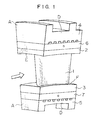
- Fig. 1 is a view showing the appearance of a ceramic stator blade unit including one blade
- Fig. 2 is a fragmentary view of a plurality of ceramic stator blade units assembled in an annular configuration.
- a retaining ring is fixedly mounted within a casing of a gas turbine, and has an axis or centerline disposed in alignment with the axis of rotation of the gas turbine, and a support ring is provided inwardly of this retaining ring in concentric relation thereto.
- the ceramic stator blades units are incorporated between the above retaining ring and support ring in an annular configuration.
- the stator blade unit comprises a blade-shaped airfoil shell 1 of a ceramic material for directing a flow of combustion gas to rotor blades (not shown) of the gas turbine, an outer sidewall 2 of a ceramic material mounted on the side of the retaining ring, and an inner sidewall 3 of a ceramic material mounted on the side of the support ring, the blade-shaped airfoil shell 1 being interposed between the outer and inner sidewalls 2 and 3.
- a passage or path of flow of the combustion gas is formed by a space defined by a lower surface E of the outer sidewall 2 and an upper surface F of the inner sidewall 3.
- the upper surface of the outer sidewall 2 is supported by an outer shroud 4 of metal through an outer heat-insulating plate 6 of a ceramic material.
- the lower surface of the inner sidewall 3 is supported by an inner shroud 5 of metal through an inner heat-insulating plate 7 of a ceramic material.
- the ceramic stator blade unit has the blade-shaped airfoil shell 1 at its central portion, and also has the sidewall, the heat-insulating plate and the shroud at each of the upper and lower portions of the unit, and the outer shroud is fixedly secured to the retaining ring whereas the inner shroud is fixedly secured to the support ring.
- An integral block (hereinafter referred to as “outer segment") is constituted by the outer shroud 4, the outer heat-insulating plate 6 and the outer sidewall 2, and similarly another integral block (hereinafter referred to as “inner segment”) is constituted by the inner sidewall 3, the inner heat-insulating plate 7 and the inner shroud 5.
- a front face A of the ceramic stator blade unit is defined by the front faces of the inner and outer segments.
- a rear face B of the blade unit is defined by the rear faces of the inner and outer segments.
- left and right side faces C and D of the blade unit are defined by one side faces of the inner and outer segments and the other side faces of these segments, respectively.
- the front face A and the rear face B are disposed respectively in planes perpendicular to the axis of rotation of the gas turbine, and are parallel to each other.
- the left side face C (not shown) and the right side face D are disposed respectively in planes, and these two planes are so disposed that the distance between the two side faces C and D becomes smaller progressively toward the inner side.
- the lower surface E of the outer sidewall 2 and the upper surface F of the inner sidewall 3 are defined respectively by parts of cylindrical surfaces disposed in concentric relation to each other.
- Fig. 2 shows a portion of one stage of the stator blades in which the ceramic stator blade units are annularly arranged at a pitch angle ⁇ .
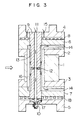
- Fig. 3 is a cross-sectional view of the ceramic stator blade unit taken in a direction of flow of the combustion gas.
- a blade core 9 of a bar-like shape extends through the axial central portion of the ceramic stator blade unit in an upward/downward direction, and the parts of the ceramic stator unit are assembled, using the blade core as a core.
- the blade core 9 is made of metal, and its upper portion is welded or integrally molded to the outer shroud 4.
- the lower portion of the blade core 9 is connected to the inner shroud 5 by a nut 10 and a bolt formed on the blade core 9.
- the blade-shaped airfoil shell 1 and the outer and inner sidewalls 2 and 3 are held against lateral movement by the blade core 9 through a heat-insulating sleeve 16 mounted on the outer periphery of the blade core 9.
- the heat-insulating plates 6 and 7 are also held against lateral movement by the blade core 9.
- the direction of flow of the cooling air is indicated by smaller arrows, and the direction of flow of the combustion gas is indicated by greater arrows.
- the cooling air fed to the lower surface of the outer shroud 4 via introduction holes 15 extending downward from the upper surface of the upper shroud 4, passes through discharge holes 8, formed in the lower surface of the outer shroud 4, to cool the outer shroud 4, and then flows into the combustion gas flow passage.
- the cooling air fed to the surface of the blade core 9 via an introduction hole 11, formed in the blade core 9 along its axis, and transverse holes 12 formed radially in the central portion of the blade core 9, passes through grooves 13, formed in the surface of the blade core 9 and extending upwardly and downwardly, to cool the blade core 9, and then flows into the combustion gas flow passage via transverse holes 14 formed in the heat-insulating plates 6 and 7.
- the cooling air fed to the upper surface of the inner shroud 5 via the introduction hole 11 of the blade core 9 and a transverse hole 17 formed in the lower portion of the blade core 9, passes through discharge holes 18 formed in the upper surface of the inner shroud 5, to cool the inner shroud 5, and then flows into the combustion gas flow passage.
- the blade-shaped airfoil shell 1 and the outer and inner sidewalls 2 and 3 are exposed directly to the combustion gas, they are made of a ceramic material excellent in heat resistance.
- a preferred example of the ceramic material is silicon carbide having an excellent strength at high temperatures and an excellent oxidation-resistance, and particularly silicon carbide sintered at normal pressure is suitable in view of the complicated shape of each of the above parts.
- Sialon and silicon nitride though slightly inferior in heat resistance and environmental resistance, may be used because of its excellent strength and toughness, depending on the conditions of use.
- Each of the heat-insulating plates 6 and 7 must be excellent in heat resistance and must have a low Young's modulus, that is, a sufficiently high elastic deformability to absorb a difference in thermal deformation amount between the blade core 9 and the ceramic parts.
- a soft inorganic material is suitable for the heat-insulating plates 6 and 7, and for example, they may be made of a woven fabric of ceramic fibers or a ceramic fiber-reinforcing ceramic.
- the sleeve 16 must have the same properties as the heat-insulating plates 6 and 7 and also must be filled in the narrow space, and therefore the sleeve 16 is made by a combination of an inorganic filler (e.g. alumina) silica compound and a soft inorganic material (e.g.
- the outer and inner shrouds 4 and and the blade core 9 are made of metal; however, since the ceramic stator blade of the present invention is superior in heat insulation than the conventional metallic stator blade, a metal material having a relatively low heat-resistance temperature, such as stainless steel, may be used, which facilitates the manufacture.
- Figs. 4 and 5 are a top plane view of the outer sidewall 2
- Fig. 5 is a front-elevational view thereof.
- an axis Z-Z is oriented in a direction parallel to the axis of rotation of the gas turbine, and is a centerline of the width (2W) of the outer sidewall 2 in the circumferential direction.
- the front face A and the rear face B are respectively flat surfaces perpendicular to the axis Z-Z, and also the left and right side faces C and D are respectively flat surfaces inclined at an angle ⁇ with respect to the axis Z-Z.
- ⁇ satisfies the following conditions. Firstly, this value must be small to prevent chipping of the ceramic part. Secondly, this value must be so determined as to enable the provision of a groove (indicated by a broken line) for fitting the blade-shaped airfoil shell 1 therein. Those portions of the groove corresponding respectively to the leading and trailing edges of the blade-shaped airfoil shell 1 are indicated by points h and i , respectively, and the portion extending between the points h and i on the circumference is indicated by X. Apexes are indicated by a , b , c and d , respectively.
- An upper surface G is a flat surface disposed radially outwardly, and the lower surface E is part of the cylindrical surface having the center disposed at the axis (centerline) O of rotation of the gas turbine.
- a plane R (perpendicular to the sheet of Fig. 5) includes the axis of rotation of the gas turbine, and is parallel to the blade core 9.
- the leading and trailing edges of the blade-shaped airfoil shell 1 are indicated by dots-and-dash lines h-j and i-k, respectively.
- An arc e-f is defined by the line of intersection between the front face A and the lower surface E, and the angle between a line e-O (passing through the point e and the point O) and a line f-O is the pitch angle ⁇ (shown in Fig. 2) of the stator blade.
- the angle formed between the line a-e of intersection between the front face A and the left side face C (not shown) and the line b-f of intersection between the front face A and the right side face D is equal to the pitch angle ⁇ so that the adjacent stator blade units can be arranged with no gap therebetween.
- the leading and trailing edges of the airfoil are distorted relative to each other so as to coincide radial lines passing through the center O of the cylindrical surface E defining the lower surface of the outer sidewall 2 (for example, the trailing edge i-k in Fig. 5 is disposed in a direction k-I).
- the airfoil of the conventional metallic stator blade has a complicated three-dimensional shape.
- the ceramic stator blade unit is required to have a simple shape to enable easy molding and working. For this reason, in this embodiment, the leading edge (indicated by the line h-j in Fig.
- the outer sidewall 2 is shaped in such a manner that the plane R for determining the position of the center of the cylindrical surface E passes the area X between the point h and the point i , thereby preventing the leading and trailing edges of the blade-shaped airfoil shell 1 from being much displaced from radial lines passing through the center O.
- the plane R is arranged to coincide with the Z-Z axis shown in Fig. 4.
- Fig. 6 shows a specific example thereof in which the angle ⁇ 1 of inclination of the left side face C (not shown) is equal to the pitch angle ⁇ , and the angle ⁇ 2 of the right side face D is O° (that is, 90° with respect to the surface G). The same effect can be achieved if this relation between the inclinations of the left and right side faces is reversed.
- Fig. 7 shows another example in which the inclination angle of each of the left and right side faces C and D is equal to a half of ⁇ .
- the angle between the surface G and the side face C, D can be the maximum (with respect to Fig. 6, this is the angle at the point a ), and this configuration is advantageous in working and handling of the sidewall made of a brittle ceramic material.
- each part is simple, the molding and working can be made easier. This is quite advantageous particularly with respect to the ceramic parts which can not be worked easily. Also, to eliminate the provision of sharp corners in the sidewall made of a ceramic material is advantageous in handling of the part and reliability. Further, since the separate or independent air passage is provided for cooling the blade core, the cooling efficiency is enhanced, thereby improving the heat resistance of the ceramic stator blade unit. The provision of the air discharge holes in the heat-insulating plates avoids damage due to thermal stress, thereby enabling the provision of the ceramic stator blade excellent in reliability.
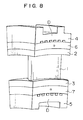
- Fig. 8 shows another embodiment of the invention.
- the surfaces of joining between adjacent parts including outer and inner sidewalls 2 and 3, outer and inner heat-insulating plates 6 and 7, and outer and inner shrouds 4 and 5) are defined respectively by parts of cylindrical surfaces having a common axis.
- the side faces are all flat, and the angle of inclination of the left side face C (not shown) as well as the angle of inclination of the right side face D is the same as described above in the above-mentioned embodiment.
- each part since the molding and working of each part become complicated, the positions of the corresponding parts in the radial direction of the turbine coincide with each other at the mated side faces of each adjacent stator blade units. This is advantageous in that the thickness of each part can be determined in view of its characteristics such as heat-resistance properties.
- Fig. 9 shows a third embodiment of the invention.
- a blade-shaped airfoil shell 1 is reduced in cross-sectional area progressively toward the inner side, and a blade core 9 is correspondingly reduced in cross-sectional area progressively toward its lower end.
- Left and right side faces (not shown) are flat, and the angle of inclination of each of the left and right side faces is the same as described in the first embodiment.
- the width of the blade-shaped airfoil shell 1 can be properly determined.
Landscapes
- Engineering & Computer Science (AREA)
- Mechanical Engineering (AREA)
- General Engineering & Computer Science (AREA)
- Chemical & Material Sciences (AREA)
- Ceramic Engineering (AREA)
- Physics & Mathematics (AREA)
- Fluid Mechanics (AREA)
- Turbine Rotor Nozzle Sealing (AREA)
Applications Claiming Priority (2)
| Application Number | Priority Date | Filing Date | Title |
|---|---|---|---|
| JP1250851A JP2777609B2 (ja) | 1989-09-27 | 1989-09-27 | セラミック静翼 |
| JP250851/89 | 1989-09-27 |
Publications (1)
| Publication Number | Publication Date |
|---|---|
| EP0420243A1 true EP0420243A1 (de) | 1991-04-03 |
Family
ID=17213950
Family Applications (1)
| Application Number | Title | Priority Date | Filing Date |
|---|---|---|---|
| EP19900118573 Withdrawn EP0420243A1 (de) | 1989-09-27 | 1990-09-27 | Keramische Statorschaufel |
Country Status (2)
| Country | Link |
|---|---|
| EP (1) | EP0420243A1 (de) |
| JP (1) | JP2777609B2 (de) |
Cited By (4)
| Publication number | Priority date | Publication date | Assignee | Title |
|---|---|---|---|---|
| EP1013885A3 (de) * | 1998-12-22 | 2001-08-01 | United Technologies Corporation | Leitschaufelbefestigung |
| EP1219787A1 (de) * | 2000-12-27 | 2002-07-03 | Siemens Aktiengesellschaft | Gasturbinenschaufel und Gasturbine |
| CN111989462A (zh) * | 2018-04-17 | 2020-11-24 | 赛峰飞机发动机公司 | 负载承载cmc喷嘴膜片 |
| US11261747B2 (en) * | 2019-05-17 | 2022-03-01 | Rolls-Royce Plc | Ceramic matrix composite vane with added platform |
Families Citing this family (1)
| Publication number | Priority date | Publication date | Assignee | Title |
|---|---|---|---|---|
| JP3316415B2 (ja) * | 1997-05-01 | 2002-08-19 | 三菱重工業株式会社 | ガスタービン冷却静翼 |
Citations (3)
| Publication number | Priority date | Publication date | Assignee | Title |
|---|---|---|---|---|
| FR57426E (fr) * | 1946-01-11 | 1953-01-28 | Perfectionnements aux turbines à gaz | |
| USB552006I5 (de) * | 1975-02-24 | 1976-02-03 | ||
| FR2463849A1 (fr) * | 1979-08-23 | 1981-02-27 | Onera (Off Nat Aerospatiale) | Perfectionnements apportes aux aubes tournantes de turbines a gaz, et aux turbines a gaz equipees de ces aubes |
Family Cites Families (4)
| Publication number | Priority date | Publication date | Assignee | Title |
|---|---|---|---|---|
| US3867065A (en) * | 1973-07-16 | 1975-02-18 | Westinghouse Electric Corp | Ceramic insulator for a gas turbine blade structure |
| JPS6189909A (ja) * | 1984-10-11 | 1986-05-08 | Central Res Inst Of Electric Power Ind | セラミツク静翼支持構造 |
| JPS6189904A (ja) * | 1984-10-11 | 1986-05-08 | Central Res Inst Of Electric Power Ind | セラミツク静翼構造 |
| JPS6189906A (ja) * | 1984-10-11 | 1986-05-08 | Central Res Inst Of Electric Power Ind | セラミツクス/金属複合静翼の冷却構造 |
-
1989
- 1989-09-27 JP JP1250851A patent/JP2777609B2/ja not_active Expired - Lifetime
-
1990
- 1990-09-27 EP EP19900118573 patent/EP0420243A1/de not_active Withdrawn
Patent Citations (3)
| Publication number | Priority date | Publication date | Assignee | Title |
|---|---|---|---|---|
| FR57426E (fr) * | 1946-01-11 | 1953-01-28 | Perfectionnements aux turbines à gaz | |
| USB552006I5 (de) * | 1975-02-24 | 1976-02-03 | ||
| FR2463849A1 (fr) * | 1979-08-23 | 1981-02-27 | Onera (Off Nat Aerospatiale) | Perfectionnements apportes aux aubes tournantes de turbines a gaz, et aux turbines a gaz equipees de ces aubes |
Non-Patent Citations (1)
| Title |
|---|
| PATENT ABSTRACTS OF JAPAN vol. 10, no. 267 (M-516)(2323) 11 September 1986, & JP-A-61 89905 (CENTRAL RESEARCH INSTITUTE OF ELECTRIC POWER) 08 May 1986, * |
Cited By (5)
| Publication number | Priority date | Publication date | Assignee | Title |
|---|---|---|---|---|
| EP1013885A3 (de) * | 1998-12-22 | 2001-08-01 | United Technologies Corporation | Leitschaufelbefestigung |
| EP1219787A1 (de) * | 2000-12-27 | 2002-07-03 | Siemens Aktiengesellschaft | Gasturbinenschaufel und Gasturbine |
| CN111989462A (zh) * | 2018-04-17 | 2020-11-24 | 赛峰飞机发动机公司 | 负载承载cmc喷嘴膜片 |
| CN111989462B (zh) * | 2018-04-17 | 2023-07-14 | 赛峰飞机发动机公司 | 负载承载cmc喷嘴膜片 |
| US11261747B2 (en) * | 2019-05-17 | 2022-03-01 | Rolls-Royce Plc | Ceramic matrix composite vane with added platform |
Also Published As
| Publication number | Publication date |
|---|---|
| JP2777609B2 (ja) | 1998-07-23 |
| JPH03115702A (ja) | 1991-05-16 |
Similar Documents
| Publication | Publication Date | Title |
|---|---|---|
| US5358379A (en) | Gas turbine vane | |
| US11078804B2 (en) | Turbine shroud assembly | |
| US4676715A (en) | Turbine rings of gas turbine plant | |
| US4480956A (en) | Turbine rotor blade for a turbomachine especially a gas turbine engine | |
| US7534086B2 (en) | Multi-layer ring seal | |
| RU2337248C2 (ru) | Теплозащитная стенка, корпус подшипника, корпус турбины для работающей на отработавших газах турбины и работающая на отработавших газах турбина (варианты) | |
| US4142836A (en) | Multiple-piece ceramic turbine blade | |
| US4390320A (en) | Tip cap for a rotor blade and method of replacement | |
| US4169694A (en) | Ceramic rotor blade having root with double curvature | |
| US8967974B2 (en) | Composite airfoil assembly | |
| US4786234A (en) | Turbine airfoil | |
| US5785496A (en) | Gas turbine rotor | |
| EP0169800A1 (de) | Zusammenbau einer Turbinenabdichtung | |
| CN110506149A (zh) | 涡轮环组件 | |
| GB2076475A (en) | Axial flow turbine shroud | |
| EP0959229B1 (de) | Niedrig belastetes Deckbandsegment für eine Turbine | |
| US5842831A (en) | Arrangement for the thermal protection of a rotor of a high-pressure compressor | |
| EP1225308B1 (de) | Geteilter Gehäusering für Gasturbinen | |
| US4511306A (en) | Combustion turbine single airfoil stator vane structure | |
| EP0728258B1 (de) | Deckbandsegment einer turbine | |
| JPH0568601B2 (de) | ||
| EP0420243A1 (de) | Keramische Statorschaufel | |
| US4580943A (en) | Turbine wheel for hot gas turbine engine | |
| EP0890710A2 (de) | Dampfkühlung für Turbinenschaufeln | |
| JPS60209604A (ja) | ガスタ−ビン静翼 |
Legal Events
| Date | Code | Title | Description |
|---|---|---|---|
| PUAI | Public reference made under article 153(3) epc to a published international application that has entered the european phase |
Free format text: ORIGINAL CODE: 0009012 |
|
| 17P | Request for examination filed |
Effective date: 19901206 |
|
| AK | Designated contracting states |
Kind code of ref document: A1 Designated state(s): DE |
|
| RIN1 | Information on inventor provided before grant (corrected) |
Inventor name: ABE, TOSHIO Inventor name: HISAMATSU, TORU Inventor name: NAKAKADO, KIMIAKI Inventor name: MIYATA, HIROSHI Inventor name: MACHIDA, TAKASHI |
|
| 17Q | First examination report despatched |
Effective date: 19920821 |
|
| STAA | Information on the status of an ep patent application or granted ep patent |
Free format text: STATUS: THE APPLICATION HAS BEEN WITHDRAWN |
|
| 18W | Application withdrawn |
Withdrawal date: 19921230 |