EP0420758B1 - Elément de couplage ultrasonore et méthode de fabrication - Google Patents
Elément de couplage ultrasonore et méthode de fabrication Download PDFInfo
- Publication number
- EP0420758B1 EP0420758B1 EP90402675A EP90402675A EP0420758B1 EP 0420758 B1 EP0420758 B1 EP 0420758B1 EP 90402675 A EP90402675 A EP 90402675A EP 90402675 A EP90402675 A EP 90402675A EP 0420758 B1 EP0420758 B1 EP 0420758B1
- Authority
- EP
- European Patent Office
- Prior art keywords
- ultrasonic
- ultrasonic probe
- acoustic medium
- ultrasonic wave
- coupler
- Prior art date
- Legal status (The legal status is an assumption and is not a legal conclusion. Google has not performed a legal analysis and makes no representation as to the accuracy of the status listed.)
- Expired - Lifetime
Links
- 238000004519 manufacturing process Methods 0.000 title claims description 10
- 239000000523 sample Substances 0.000 claims description 117
- 230000003100 immobilizing effect Effects 0.000 claims description 56
- 230000001902 propagating effect Effects 0.000 claims description 35
- XLYOFNOQVPJJNP-UHFFFAOYSA-N water Substances O XLYOFNOQVPJJNP-UHFFFAOYSA-N 0.000 claims description 28
- 238000000034 method Methods 0.000 claims description 26
- 238000004132 cross linking Methods 0.000 claims description 22
- 229920003169 water-soluble polymer Polymers 0.000 claims description 22
- 230000005540 biological transmission Effects 0.000 claims description 21
- 239000007864 aqueous solution Substances 0.000 claims description 17
- 230000005855 radiation Effects 0.000 claims description 13
- 229920002125 Sokalan® Polymers 0.000 claims description 12
- 239000004584 polyacrylic acid Substances 0.000 claims description 12
- -1 alkali metal salts Chemical class 0.000 claims description 11
- 229920003171 Poly (ethylene oxide) Polymers 0.000 claims description 9
- 229910052783 alkali metal Inorganic materials 0.000 claims description 8
- 229920000642 polymer Polymers 0.000 claims description 8
- 150000001875 compounds Chemical class 0.000 claims description 5
- 229920002401 polyacrylamide Polymers 0.000 claims description 5
- 239000004372 Polyvinyl alcohol Substances 0.000 claims description 4
- 150000001340 alkali metals Chemical class 0.000 claims description 4
- 230000036961 partial effect Effects 0.000 claims description 4
- 229920002451 polyvinyl alcohol Polymers 0.000 claims description 4
- 229920000036 polyvinylpyrrolidone Polymers 0.000 claims description 4
- 239000001267 polyvinylpyrrolidone Substances 0.000 claims description 4
- 235000013855 polyvinylpyrrolidone Nutrition 0.000 claims description 4
- 230000007423 decrease Effects 0.000 claims description 3
- 238000006386 neutralization reaction Methods 0.000 claims description 3
- 239000000499 gel Substances 0.000 description 19
- 238000006243 chemical reaction Methods 0.000 description 7
- 238000003745 diagnosis Methods 0.000 description 6
- 230000005251 gamma ray Effects 0.000 description 6
- 210000000056 organ Anatomy 0.000 description 6
- 239000004793 Polystyrene Substances 0.000 description 5
- 230000000694 effects Effects 0.000 description 5
- 229920002223 polystyrene Polymers 0.000 description 5
- 210000004204 blood vessel Anatomy 0.000 description 4
- 230000006735 deficit Effects 0.000 description 4
- 230000033001 locomotion Effects 0.000 description 4
- 229920000515 polycarbonate Polymers 0.000 description 4
- 239000004417 polycarbonate Substances 0.000 description 4
- 239000000243 solution Substances 0.000 description 4
- 239000004743 Polypropylene Substances 0.000 description 3
- 230000002421 anti-septic effect Effects 0.000 description 3
- 239000008367 deionised water Substances 0.000 description 3
- 229910021641 deionized water Inorganic materials 0.000 description 3
- 230000000994 depressogenic effect Effects 0.000 description 3
- 230000001747 exhibiting effect Effects 0.000 description 3
- 208000019622 heart disease Diseases 0.000 description 3
- 238000003780 insertion Methods 0.000 description 3
- 230000037431 insertion Effects 0.000 description 3
- 230000003902 lesion Effects 0.000 description 3
- 229920001155 polypropylene Polymers 0.000 description 3
- 208000020446 Cardiac disease Diseases 0.000 description 2
- ZGTMUACCHSMWAC-UHFFFAOYSA-L EDTA disodium salt (anhydrous) Chemical compound [Na+].[Na+].OC(=O)CN(CC([O-])=O)CCN(CC(O)=O)CC([O-])=O ZGTMUACCHSMWAC-UHFFFAOYSA-L 0.000 description 2
- 229960000686 benzalkonium chloride Drugs 0.000 description 2
- CADWTSSKOVRVJC-UHFFFAOYSA-N benzyl(dimethyl)azanium;chloride Chemical compound [Cl-].C[NH+](C)CC1=CC=CC=C1 CADWTSSKOVRVJC-UHFFFAOYSA-N 0.000 description 2
- 238000010586 diagram Methods 0.000 description 2
- 238000010894 electron beam technology Methods 0.000 description 2
- 230000001965 increasing effect Effects 0.000 description 2
- 229920003023 plastic Polymers 0.000 description 2
- 239000004033 plastic Substances 0.000 description 2
- 229940037001 sodium edetate Drugs 0.000 description 2
- 230000001954 sterilising effect Effects 0.000 description 2
- 238000004659 sterilization and disinfection Methods 0.000 description 2
- 239000000126 substance Substances 0.000 description 2
- 210000001519 tissue Anatomy 0.000 description 2
- AOSZTAHDEDLTLQ-AZKQZHLXSA-N (1S,2S,4R,8S,9S,11S,12R,13S,19S)-6-[(3-chlorophenyl)methyl]-12,19-difluoro-11-hydroxy-8-(2-hydroxyacetyl)-9,13-dimethyl-6-azapentacyclo[10.8.0.02,9.04,8.013,18]icosa-14,17-dien-16-one Chemical compound C([C@@H]1C[C@H]2[C@H]3[C@]([C@]4(C=CC(=O)C=C4[C@@H](F)C3)C)(F)[C@@H](O)C[C@@]2([C@@]1(C1)C(=O)CO)C)N1CC1=CC=CC(Cl)=C1 AOSZTAHDEDLTLQ-AZKQZHLXSA-N 0.000 description 1
- SZUVGFMDDVSKSI-WIFOCOSTSA-N (1s,2s,3s,5r)-1-(carboxymethyl)-3,5-bis[(4-phenoxyphenyl)methyl-propylcarbamoyl]cyclopentane-1,2-dicarboxylic acid Chemical compound O=C([C@@H]1[C@@H]([C@](CC(O)=O)([C@H](C(=O)N(CCC)CC=2C=CC(OC=3C=CC=CC=3)=CC=2)C1)C(O)=O)C(O)=O)N(CCC)CC(C=C1)=CC=C1OC1=CC=CC=C1 SZUVGFMDDVSKSI-WIFOCOSTSA-N 0.000 description 1
- 229940126657 Compound 17 Drugs 0.000 description 1
- 239000004593 Epoxy Substances 0.000 description 1
- 230000003187 abdominal effect Effects 0.000 description 1
- 230000004308 accommodation Effects 0.000 description 1
- 239000000853 adhesive Substances 0.000 description 1
- 239000012491 analyte Substances 0.000 description 1
- 206010003119 arrhythmia Diseases 0.000 description 1
- 230000006793 arrhythmia Effects 0.000 description 1
- 230000002238 attenuated effect Effects 0.000 description 1
- 230000036772 blood pressure Effects 0.000 description 1
- 210000000988 bone and bone Anatomy 0.000 description 1
- 210000000038 chest Anatomy 0.000 description 1
- 229940126543 compound 14 Drugs 0.000 description 1
- 229920006037 cross link polymer Polymers 0.000 description 1
- 230000003247 decreasing effect Effects 0.000 description 1
- 230000000593 degrading effect Effects 0.000 description 1
- 230000002708 enhancing effect Effects 0.000 description 1
- 230000008014 freezing Effects 0.000 description 1
- 238000007710 freezing Methods 0.000 description 1
- 239000000017 hydrogel Substances 0.000 description 1
- 239000012948 isocyanate Substances 0.000 description 1
- 210000004185 liver Anatomy 0.000 description 1
- 210000004072 lung Anatomy 0.000 description 1
- 230000000149 penetrating effect Effects 0.000 description 1
- 210000003516 pericardium Anatomy 0.000 description 1
- 230000002093 peripheral effect Effects 0.000 description 1
- 230000002980 postoperative effect Effects 0.000 description 1
- 238000010882 preoperative diagnosis Methods 0.000 description 1
- 238000003825 pressing Methods 0.000 description 1
- 230000002265 prevention Effects 0.000 description 1
- 230000000717 retained effect Effects 0.000 description 1
- 239000003381 stabilizer Substances 0.000 description 1
- 210000001562 sternum Anatomy 0.000 description 1
- 238000003756 stirring Methods 0.000 description 1
- 238000001356 surgical procedure Methods 0.000 description 1
- 229920005992 thermoplastic resin Polymers 0.000 description 1
Images


Classifications
-
- A—HUMAN NECESSITIES
- A61—MEDICAL OR VETERINARY SCIENCE; HYGIENE
- A61B—DIAGNOSIS; SURGERY; IDENTIFICATION
- A61B8/00—Diagnosis using ultrasonic, sonic or infrasonic waves
- A61B8/42—Details of probe positioning or probe attachment to the patient
- A61B8/4272—Details of probe positioning or probe attachment to the patient involving the acoustic interface between the transducer and the tissue
- A61B8/4281—Details of probe positioning or probe attachment to the patient involving the acoustic interface between the transducer and the tissue characterised by sound-transmitting media or devices for coupling the transducer to the tissue
-
- G—PHYSICS
- G10—MUSICAL INSTRUMENTS; ACOUSTICS
- G10K—SOUND-PRODUCING DEVICES; METHODS OR DEVICES FOR PROTECTING AGAINST, OR FOR DAMPING, NOISE OR OTHER ACOUSTIC WAVES IN GENERAL; ACOUSTICS NOT OTHERWISE PROVIDED FOR
- G10K11/00—Methods or devices for transmitting, conducting or directing sound in general; Methods or devices for protecting against, or for damping, noise or other acoustic waves in general
- G10K11/02—Mechanical acoustic impedances; Impedance matching, e.g. by horns; Acoustic resonators
-
- A—HUMAN NECESSITIES
- A61—MEDICAL OR VETERINARY SCIENCE; HYGIENE
- A61B—DIAGNOSIS; SURGERY; IDENTIFICATION
- A61B17/00—Surgical instruments, devices or methods
- A61B17/22—Implements for squeezing-off ulcers or the like on inner organs of the body; Implements for scraping-out cavities of body organs, e.g. bones; for invasive removal or destruction of calculus using mechanical vibrations; for removing obstructions in blood vessels, not otherwise provided for
- A61B17/225—Implements for squeezing-off ulcers or the like on inner organs of the body; Implements for scraping-out cavities of body organs, e.g. bones; for invasive removal or destruction of calculus using mechanical vibrations; for removing obstructions in blood vessels, not otherwise provided for for extracorporeal shock wave lithotripsy [ESWL], e.g. by using ultrasonic waves
- A61B17/2251—Implements for squeezing-off ulcers or the like on inner organs of the body; Implements for scraping-out cavities of body organs, e.g. bones; for invasive removal or destruction of calculus using mechanical vibrations; for removing obstructions in blood vessels, not otherwise provided for for extracorporeal shock wave lithotripsy [ESWL], e.g. by using ultrasonic waves characterised by coupling elements between the apparatus, e.g. shock wave apparatus or locating means, and the patient, e.g. details of bags, pressure control of bag on patient
- A61B2017/2253—Implements for squeezing-off ulcers or the like on inner organs of the body; Implements for scraping-out cavities of body organs, e.g. bones; for invasive removal or destruction of calculus using mechanical vibrations; for removing obstructions in blood vessels, not otherwise provided for for extracorporeal shock wave lithotripsy [ESWL], e.g. by using ultrasonic waves characterised by coupling elements between the apparatus, e.g. shock wave apparatus or locating means, and the patient, e.g. details of bags, pressure control of bag on patient using a coupling gel or liquid
Definitions
- This invention relates to an ultrasonic coupler and a method for the production thereof. More particularly, it relates to an ultrasonic coupler to be interposed between an ultrasonic probe used in the field of bioinstrumentation utilizing an ultrasonic wave and the surface of contact of an ultrasonic probe with an analyte under test and to a method for the production thereof.
- the ultrasonic diagnostic apparatus owing to the simplicity of handling and the obviation of the necessity for penetrating a patient's body, has found utility in numerous fields of diagnosis represented by those directed to the abdominal organs such as the heart and the liver.
- the ultrasonic examination to be performed during the course of a cardiotomy may be conceived.
- the ultrasonic examination is performed after a median incision of the sternum by directly applying a probe externally on the pericardium, the heart, or the blood vessel prior to the incision thereof affords the surgeon a detailed surgically useful diagnosis concerning the pertinent internal cavity.
- the diagnosis enables the surgeon, in the course of operation, to confirm whether or not the surgical treatment initiated in consequence of the ultrasonic examination is adequate. This fact is important for preventing repetition of surgical operations and conducting postoperative management of the operated organ.
- a cross-sectional image of a living body is obtained by a process which comprises projecting an ultrasonic pulse toward the interior of the body from the surface of the body or the surface of a relevant organ and receiving a reflected wave to be produced by the difference between acoustic impedances proper to varying tissues within the living body.
- the ultrasonic probe should be applied to the surface of a body or the surface of a relevant organ tightly enough to preclude intervention of an air layer which exhibits a high reflectance to the ultrasonic wave.
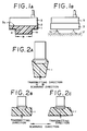
- a projected part 1a of the portion of an elastic acoustic medium 1 which is destined to contact a subject 2 under test is projected from an opening 4 on the subject side of an immobilizing member 3 in the same width as the width W of the opening, namely in the identical area with the area of the opening as illustrated in Fig. 1A and Fig. 1B (JP-A-61-288,840(1986)).
- the surface of the elastic acoustic medium 1 which contacts an ultrasonic wave-receiving surface 5a of an ultrasonic probe 5 has a flat shape.
- an ultrasonic coupler so shaped that the cross section of the elastic acoustic medium 1 taken perpendicularly to the direction of ultrasonic scanning decreases in width in the direction of transmission of ultrasonic wave as illustrated in Fig. 2A, Fig. 2B and Fig. 2C (JP-A-63-36,173(1988)) and an ultrasonic coupler so shaped that the cross section of the elastic acoustic medium 1 taken parallelly to the direction of ultrasonic scanning and also to the direction of ultrasonic wave transmission has a rectangular shape or has a width increasing in the direction of the ultrasonic wave transmission (JP-A-63-117,734 & 5 (1988)).
- the conventional ultrasonic couplers of this kind invariably have an elastic acoustic medium 1 projected toward the subject side from the immobilizing member.
- the elastic acoustic medium projects from the subject side opening of the immobilizing member in the same width as the width of the opening as found in the conventional ultrasonic couplers, however, a movement of the ultrasonic coupler on the subject 2 results in impairment of a produced image because the elastic acoustic medium 1 is inevitably flexed and the desired transmission and reception of an ultrasonic wave is consequently obstructed as illustrated in Fig. 1B. Otherwise, the flexure of the elastic acoustic medium 1 poses a problem that the elastic acoustic medium eventually sustains breakage.
- the surface of the elastic acoustic medium 1 destined to contact the surface of the ultrasonic probe 5 for transmitting and receiving an ultrasonic wave is flat, bubbles (air) are suffered to enter the surface of contact which is formed between the elastic acoustic medium and the surface of the ultrasonic probe for transmitting and receiving an ultrasonic wave during the attachment of the ultrasonic coupler to the ultrasonic probe.
- the entrapped bubbles pose a problem that the transmission of an ultrasonic wave to the subject is not carried out favorably.
- the size of the ultrasonic coupler is limited to the visible dimensions of the ultrasonic probe and, as a result, the shape of the ultrasonic coupler is larger than the area in which the ultrasonic beam is transmitted and received. This fact constitutes itself a factor for degrading the contacting property of the ultrasonic coupler with the subject or the scanning property of the ultrasonic coupler on the subject.
- DE-A-3 429 939 relates to an ultrasonic coupler medium to be used for detecting an object, the ultrasonic speed being adjusted to that of the object, characterized in that the coupler medium is in particular a hydro-gel or a polyacrylamide gel.
- An object of this invention is to provide a novel ultrasonic coupler.
- Another object of this invention is to provide an ultrasonic coupler which precludes the impairment of a produced image due to the retaining property of the elastic acoustic medium and the flexure of the elastic acoustic medium and the entrapment of bubbles during the attachment of the ultrasonic coupler to the ultrasonic probe and, which is more, improves the contacting property with the subject and the operability.
- a further object of this invention is to provide an ultrasonic coupler which allows simple manufacture and easy handling and has been sterilized and a method for the production thereof.
- an ultrasonic coupler provided with an ultrasonic wave propagating member formed of a water-containing polymeric gel and a holder for accommodating the propagating member and fixing it to a probe
- the ultrasonic coupler intended to be interposed between a subject under test and an ultrasonic probe for transmitting and receiving an ultrasonic wave to and from the subject under test and characterized by the fact that the ultrasonic wave propagating member is a water-containing polymeric gel produced by integrally cross-linking an aqueous solution of a water-soluble polymeric compound with the holder inside the holder.
- a method for the production of an ultrasonic coupler to be interposed between a subject under test and an ultrasonic probe for transmitting and receiving an ultrasonic wave to and from the subject under test comprises the steps of supplying an aqueous solution of a water-soluble polymeric compound into a holder of the ultrasonic coupler provided with an ultrasonic wave propagating member formed of a water-containing polymeric gel and the holder for accommodating the propagating member and fixing it to the ultrasonic probe said method being characterized by subsequently cross-linking the polymeric compound thereby forming a water-containing polymeric gel in consequence of integrally cross-linking the polymeric compound with the holder inside the holder.
- This invention further discloses an ultrasonic coupler and a method for the production thereof, wherein the cross-linking of the water-soluble polymeric compound is accomplished by exposure of the compound to a radiation, preferably to the ⁇ ray.
- This invention further discloses an ultrasonic coupler and a method for the production thereof, wherein the water-soluble polymeric compound is at least one member selected from the group consisting of polyvinyl alcohol, polyvinyl pyrrolidone, polyethylene oxide, polyacrylamide, polyacrylic acid, alkali metal salts of polyacrylic acid, and products of partial neutralization of polyacrylic acid with alkali metals.
- an ultrasonic coupler provided with an elastic acoustic medium intended to be interposed between an ultrasonic probe and a subject under test and possessed of surfaces for contact with both an ultrasonic wave-transmitting and -receiving surface of the ultrasonic probe and the subject under test and an immobilizing member adapted to accommodate the elastic acoustic medium, possessed of openings one each on the ultrasonic probe side and the subject side, and enabled to be attached to or detached from the ultrasonic probe, the cross section of the elastic acoustic medium taken perpendicularly to the direction of transmission of an ultrasonic wave exceeding the area of the subject side opening of the immobilizing member and, at the same time, projecting past the leading end of the immobilizing member.
- This invention further discloses an ultrasonic coupler, wherein part or the whole of the surfaces of the elastic acoustic medium for contact with the ultrasonic wave-transmitting and -receiving surface of the ultrasonic probe possess a convexly curbed contour.
- This invention further discloses an ultrasonic coupler, wherein attaching parts are disposed above the ultrasonic probe side opening part of the immobilizing member in such a manner as to contact at least a pair of opposed lateral surfaces of the ultrasonic probe and the interval between the opposed attaching parts is smaller than the width of the corresponding ultrasonic probe.
- This invention further discloses an ultrasonic coupler, wherein part or the whole of the lateral surfaces of the elastic acoustic medium are formed in a convex or concave contour and, at the same time, the corresponding inner walls of the immobilizng member are formed in a concave or convex contour.
- This invention further discloses an ultrasonic coupler, wherein the ultrasonic coupler is so shaped that the cross section of the ultrasonic coupler taken parallelly to the direction of ultrasonic scanning and also to the direction of ultrasonic wave transmission decreases in width in the direction of transmission of an ultrasonic wave.
- an ultrasonic coupler provided with an elastic acoustic medium intended to be interposed between an ultrasonic probe and a subject under test and possessed of surfaces for contact with both an ultrasonic wave-transmitting and -receiving surface of the ultrasonic probe and the subject under test and an immobilizing member adapted to accommodate the elastic acoustic medium, possessed of openings one each on the ultrasonic probe side and the subject side, and enabled to be attached to or detached from the ultrasonic probe, with a part or the whole of the surfaces of the elastic acoustic medium for contact with the ultrasonic wave-transmitting and -receiving surface of the ultrasonic probe assumeing a convexly curved contour, the elastic acoustic medium being so shaped as to be substantially flush with the leading end surface of the subject side opening part of the immobilizing member, and the elastic acoustic medium projecting past the leading end surface of the opening part when the immobilizing member is attached to the ultra
- This invention further discloses an ultrasonic coupler, wherein attaching parts are disposed above the ultrasonic probe side opening part of the immobilizing member in such a manner as to contact at least a pair of opposed lateral surfaces of the ultrasonic probe and the interval between the opposed attaching parts is smaller than the width of the corresponding ultrasonic probe.
- this invention is directed to an ultrasonic coupler provided with an ultrasonic wave propagating member formed of a water-containing polymeric gel and a holder for accommodating the propagating member and fixing it to the ultrasonic probe, which ultrasonic coupler is intended to be interposed between a subject under test and the ultrasonic probe for transmitting and receiving an ultrasonic wave to and from the subject under test and characterized by the fact that the ultrasonic wave propagating member is a water-containing polymeric gel produced by integrally cross-linking an aqueous solution of a water-soluble polymeric compound with the holder inside the holder.
- This ultrasonic coupler is produced by supplying an aqueous solution of a water-soluble polymeric compound to the interior of the holder and then subjecting the polymeric compound to a cross-linking reaction thereby forming a water-containing polymeric gel integrally cross-linked with the holder inside the holder.
- the ultrasonic coupler therefore, enjoys ease of handling because it obviates the necessity for attaching the ultrasonic wave propagating member fast to the holder each time the coupler is used on the probe. Even when the water-containing polymeric gel has low mechanical strength, it enjoys enhanced fastness of adhesion to the subject, imparts notably improved operability to the probe, and exhibits an improved efficiency in the transmission of an ultrasonic wave because this gel can be immobilized to the holder.
- the ultrasonic wave propagating member is cross-linked by being exposed to a radiation such as, for example, the ray
- a radiation such as, for example, the ray
- this ultrasonic coupler can be put directly to use in a surgical operation or in centesis which dictates sterilization.
- This invention is further directed to an ultrasonic coupler provided with an elastic acoustic medium intended to be interposed between an ultrasonic probe and a subject under test and possessed of surfaces for contact wth both an ultrasonic wave-transmitting and -receiving surface of the ultrasonic probe and the subject under test and an immobilizing member adapted to accommodate the elastic acoustic medium, possessed of openings one each on the ultrasonic probe side and the subject side, and enabled to be attached to or detached from the ultrasonic probe, the cross section of the elastic acoustic medium taken perpendicularly to the direction of transmission of an ultrasonic wave exceeding the area of the subject side opening of the immobilizing member and, at the same time, projecting past the leading end of the immobilizing member.
- the ultrasonic coupler provided by this invention therefore, is enabled to establish contact very satisfactorily with the subject under test, retain the elastic acoustic medium with improved fastness therein, ensure highly satisfactory fulfilment of the transmission and reception of an ultrasonic wave, and facilitate the prevention of entrapment of bubbles during the attachment of the ultrasonic coupler to the ultrasonic probe and the location of the ultrasonic coupler relative to the ultrasonic wave-transmitting and - receiving surface of the ultrasonic probe.
- this invention is directed to an ultrasonic coupler provided with an elastic acoustic medium intended to be interposed between an ultrasonic probe and a subject under test and possessed of surfaces for contact with both an ultrasonic wave-transmitting and -receiving surface of the ultrasonic probe and the subject under test and an immobilizing member adapted to accommodate the elastic acoustic medium, possessed of openings one each on the ultrasonic probe side and the subject side, and enabled to be attached to or detached from the ultrasonic probe, with a part or the whole of the surfaces of the elastic acoustic medium for contact with the ultrasonic wave-transmitting and -receiving surface of the ultrasonic probe assumeing a convexly curved contour, the elastic acoustic medium being so shaped as to be substantially flush with the leading end surface of the subject side opening part of the immobilizing member, and the elastic acoustic medium projecting past the leading end surface of the opening part when the immobilizing member is attached to the ultrasonic
- the ultrasonic coupler therefore, enjoys the advantage that, while the ultrasonic coupler is not in use, the elastic acoustic medium has a very remote possibility of contacting other objects and consequently keeps the leading end surface thereof from defilement and, after the ultrasonic coupler has been attached to the ultrasonic probe, the insertion of the ultrasonic probe under pressure results in projecting the elastic acoustic medium from the leading end surface of the subject side opening of the immobilizing member and consequently forming a desired projected part and enabling the elastic acoustic medium to contact the subject under test very satisfactorily.
- Fig. 1A is a cross section of a conventional ultrasonic coupler.
- Fig. 1B is a side elevation of the ultrasonic coupler of Fig. 1A.
- Figs. 2A to 2C are cross sections each of a varying conventional ultrasonic coupler.
- Fig. 3 is a cross section illustrating an ultrasonic coupler of the present invention in a state undergoing the process of production.
- Fig. 4A is a cross section of the ultrasonic coupler of the present invention.
- Fig. 4B is a side elevation of the ultrasonic coupler of Fig. 4A.
- Fig. 5 is a cross section illustrating the ultrasonic coupler of the present invention in a state undergoing the process of use.
- Figs. 6A to 6C are cross sections each illustrating a varying ultrasonic coupler as other embodiment of the present invention.
- Fig. 7 is a cross section illustrating the ultrasonic coupler of Fig. 6B in a state undergoing the process of use.
- Fig. 8A is a cross section illustrating an ultrasonic coupler as yet another embodiment of this invention.
- Fig. 8B is a cross section illustrating the ultrasonic coupler of Fig. 8A in a state undergoing the process of use.
- Fig. 9 is an exploded perspective view illustrating an ultrasonic coupler as still another embodiment of this invention.
- Fig. 10A is a cross section taken through Fig. 9 illustrating the ultrasonic coupler in a state having an elastic acoustic medium attached to a immobilizing member.
- Fig. 10B is a cross section taken through Fig. 10A along the line Xb-Xb.
- Fig. 11A and Fig. 11B are cross sections illustrating a further embodiment of this invention.
- Fig. 12A is a cross section illustrating an ultrasonic coupler as still another embodiment of this invention.
- Fig. 12B is a cross section illustrating the ultrasonic coupler in a state of attachment to an ultrasonic probe.
- This invention concerns an ultrasonic coupler provided with an ultrasonic wave propagating member formed of a water-containing polymeric gel and a holder for accommodating the propagating member and fixing it to the ultrasonic probe, which ultrasonic coupler is intended to be interposed between a subject under test and the ultrasonic probe for transmitting and receiving an ultrasonic wave to and from the subject under test and characterized by the fact that the ultrasonic wave propagating member is a water-containing polymeric gel produced by integrally cross-linking an aqueous solution of a water-soluble polymeric compound with the holder inside the holder.
- This ultrasonic coupler is produced by supplying an aqueous solution of a water-soluble polymeric compound to the interior of the holder and then subjecting the polymeric compound to a cross-linking reaction thereby forming a water-containing polymeric gel integrally cross-linked with the holder within the holder.
- the water-soluble polymeric compounds which are effectively usable in this invention include polyvinyl alcohol, polyvinyl pyrrolidone, polyethylene oxide, polyacrylamide, polyacrylic acid, alkali metal salts of polyacrylic acid, and products of partial neutralzation of polyacrylic acid with alkali metals.
- polyethylene oxide proves to be most preferable.
- the molecular weight of this polyethylene oxide is required to exceed 100,000 and desired to be in the range of 200,000 to 8,000,000.
- the cross-linking of the water-soluble polymeric compound can be carried out by various method.
- a method which effects this reaction with a polyfunctional isocyanate compound or a polyfunctional epoxy compound, a method which effects this reaction by irradiation with a radiation, and a method which effects the reaction by freezing and defrosing the compound may be cited, for example.
- the method resorting to the exposure to a radiation proves to be particularly preferable in the sense that this exposure fulfils sterilization concurrently with the cross-linking.
- the cross-linking by the exposure to a radiation is accomplished by placing an aqueous solution of the water-soluble polymeric compound in the aforementioned holder and exposing this aqueous solution to a radiation thereby three-dimensionally cross-linking the polymer and allowing 80 to 99% by weight, preferably 90 to 98% by weight, of water be contained in the reticular texture of the resultant cross-linked polymer.
- the reason for this range of water content is that the ultrasonic wave is attenuated to an unduly large extent if the water content is less than 80% by weight and the mechanical strength of the ultrasonic wave propagating medium is inferior if the water content exceeds 99% by weight.
- the concentration of the water-soluble polymeric compound in the aforementioned aqueous solution is in the range of 1 to 20% by weight, preferably 2 to 10% by weight.
- the aqueous solution may incorporate therein an antiseptic and a stabilizer.
- the radiations which are effectively usable herein for the sake of the cross-linking include ⁇ -ray and electron beam, for example.
- the ⁇ -ray proves to be more preferable than the electron beam.
- the dosage of the radiation is in the range of 0.25 to 2.5 Mrads, preferably 0.5 to 1.5 Mrads. The reason for this range of dosage is that the cross-linking does not proceed to a sufficient degree and the product of this cross-linking reaction holds the shape of its own only with difficulty if the dosage is less than 0.25 Mrad and the product of the cross-linking reaction gains excessively in rigidity, exhibits insufficient flexibility, and suffers from unduly low fastness of adhesion to the contour of a given site for contact.
- the holder is generally made of a thermoplastic resin such as, for example, polycarbonate polystyrene, or polypropylene.
- Figs. 3 to 5 represent one embodiment of this invention.
- a lower opening part 11 of a holder 12 which has the opening part 11 provided in the bottom part thereof is closed by having a lower lid 13 tacked optionally by the use of an adhesive agent or helically attached thereto.
- an aqueous solution of a water-soluble polymeric compound 14 is poured into the holder through an upper opening part 15.
- an upper lid 16 is inserted through the upper opening part 15 and fixed in such a manner as to establish tight contact throughout with the surface of the aforementioned aqueous solution 14.
- the aqueous solution 14 as retained in the holder 12 is either exposed to a radiation or frozen and defrosted to cross-link and solidify the water-soluble polymeric compound and give rise to an ultrasonic wave propagating member 17 formed of a water-containing polymeric gel.
- an ultrasonic coupler is obtained which has the water-containing polymeric compound 17 integrally cross-linked with the holder 12.
- the use of the ultrasonic coupler which has been produced as described above is accomplished by removing the upper and lower lids 13 and 16, inserting an ultrasonic probe 18 through the upper opening part 15, fixing an acoustic radiation surface 19 of the probe 18 tightly in the ultrasonic wave propagating member 17, and then manipulating the probe 18 while keeping a contact surface 21 between the ultrasonic wave propagating member 17 and a subject 20 under test in tight adhesion to the subject 20 under test.
- the use of the ultrasonic coupler constructed as described above can be readily attained simply by fixing the holder 12 to the ultrasonic probe 18 because the holder 12 and the ultrasonic wave propagating member 17 are integrally joined.
- Figs. 6A to 6C represent another embodiment of this invention.
- an ultrasonic coupler illustrated in Fig. 6A is similar to the ultrasonic coupler shown in Fig. 4A, except that a stopper part 43 is formed in an ultrasonic wave propagating member 37 by digging at least one depressed part 42 wholly or partly in circumference in the inner wall of a holder 32.
- an ultrasonic coupler illustrated in Fig. 6B is similar to the ultrasonic coupler shown in Fig. 6B, except that the leading end part (a lower opening part 31) of the ultrasonic wave propagating member 37 is formed in an area larger than the area of the opening part just mentioned.
- an ultrasonic coupler illustrated in Fig. 6C is similar to the ultrasonic coupler shown in Fig. 6A, except that the effectiveness of contact of the surface of the ultrasonic wave propagating member 37 with the leading end part of a probe 38 is enhanced by using an upwardly curved upper lid 36 thereby allowing the resultantly formed ultrasonic wave propagating member 37 to acquire an upwardly curved surface.
- Fig. 8A and Fig. 8B represent still other embodiments of this invention.
- a stopper part 63 is formed in the ultrasonic wave propagating member 57 by digging at least one depressed part 62 wholly or partly in circumference in the inner wall of the holder 52. Further, since the width of a surface 61 of the ultrasonic wave propagating member 57 for contact with a subject 60 under test is larger than a lower opening part 51 of the holder 52, the holder 52 has no possibility of contacting the subject 60 under test and, as the result, the fastness contact with the subject 60 is further enhanced. Since, in this case, the subject side opening part (lower opening part) 51 is larger than the probe side opening part (upper opening part) 55, the multiple reflection of an ultrasonic wave on the inner wall of the holder 52 is inconspicuous.
- An ultrasonic coupler illustrated in Fig. 9, Fig. 10A, and Fig. 10B as representing another embodiment of this invention comprises an elastic acoustic medium 71 solidified in the form of gel and an immobilizing member 73 capable of causing this elastic acoustic medium 71 to be attached fast to and detatched from an ultrasonic wave-transmitting and - receiving surface 72a of an ultrasonic probe 72.
- the elastic acoustic member 71 has the widths Wa and Wb of a surface 71b thereof for contact with a subject under test enlarged beyond the widths Wa' and Wb' of the subject side opening of the part of the immobilizing member 73 medium 71 accommodating the elastic acoustic and the elastic acoustic member 71 protrudes from the leading end of the immobilizing member 73. More specifically, the cross section of the elastic acoustic medium 71 taken along a direction perpendicular to the direction of transmission of an ultrasonic wave from the elastic acoustic medium 71 exceeds the area of the subject side opening of the immobilizing member 73 and protrudes past the leading end of the immobilizing member 73.
- the subject side surface 73a of the immobilizing member 73 is destined to press down a peripheral part 71c of the elastic acoustic medium 71 when the ultrasonic coupler is moved on the subject. Consequently, the flexure (deformation) of the elastic acoustic medium 71 is lessened and the otherwise possible impairment of propagation of an ultrasonic wave can be precluded by the retaining property and flexure of the elastic acoustic medium 71. Further, the part 71a of the elastic acoustic medium 71 for contact with the ultrasonic wave-transmitting and -receiving surface 72a of the ultrasonic probe 72 is convexly curved.
- convex parts 71d or concave parts (not shown) corresponding to the concave parts 73d or convex parts (not shown) of the immobilizing member 73 are formed one each.
- the immobilizing member 73 is formed of a hard plastic substance such as, for example, polycarbonate, polystyrene, or polypropylene.
- the opening of the immobilizing member 73 parallel to the visible dimensions of the ultrasonic probe 73 possesses widths Da and Db.
- An attaching part 73b for the ultrasonic probe 72 is formed on at least one pair of opposed lateral surfaces in the lateral surfaces of the opening. This attaching part 73b is so formed that the interval L between the opposed lateral surfaces is smaller than the width L' of the corresponding ultrasonic probe 72.
- the immobilizing member 73 owing to the elasticity thereof, nips the ultrasonic probe 72. Further, as illustrated in Fig.
- concave parts 73d conforming to the convex parts 71d of the lateral surfaces of the elastic acoustic medium 71 are formed on the inner walls.
- the elastic acoustic medium 71 is immobilized by fitting into the concave parts 73d the convex parts 71d formed on the lateral surfaces of the elastic acoustic medium 71. Otherwise, the immobilization of the elastic acoustic medium 71 is attained by supplying the aqueous solution mentioned above and cross-linking the polymeric compound in the aqueous solution integrally with the elastic acoustic medium 71.
- the cross section of the immobilizing member 73 taken in a direction perpendicular to the direction of ultrasonic scanning and also to the direction of transmission of an ultrasonic wave is decreased in width in the direction of transmission of an ultrasonic wave as illustrated in Fig. 10A.
- This invention has been described with reference to one embodiment thereof.
- this embodiment of the invention has been depicted as one having the convexly curved parts of the elastic acoustic medium 71 formed only in the cross section perpendicular to the direction of ultrasonic scanning, these curved parts may be formed in the cross section parallel to the direction of ultrasonic scanning or on the entire surface for contact with the ultrasonic wave-transmitting and -receiving surface.
- the concave and convex parts formed on the lateral surfaces of the elastic acoustic medium 71 and the inner wall of the immobilizing member 73 may be otherwise formed on part or the whole of the lateral surfaces or the concave and convex parts may be formed inversely.
- the attaching parts 73b for the ultrasonic probe 72 which are provided for the immobilizing member 73 are formed in the present embodiment only on one pair of opposed lateral surfaces, they may be formed on the four lateral surfaces perpendicularly intersecting the opening surface.
- This invention may be adapted not merey for a linear array probe but also for a simple probe, a mechanical scan probe, and a convex probe, for example (Refer Fig. 11A and Fig. 11B.
- the reference numerals which are the sums of the reference numerals of Fig. 9, Fig. 10A, and Fig. 10B plus 10 denote identical component parts.).
- the cross section of the elastic acoustic medium taken in a directon perpendicular to the direction of ultrasonic transmission is required to exceed the area of the subject side opening of the immobilizing member and protrude past the leading end of the immobilizing member.
- the surface of the edge defining the subject side opening part of the immobilizing member manifests the effect of pressing the part of the elastic acoustic medium protruding along the immobilizing member and enhancing the retaining property of the elastic acoustic medium.
- the flexure suffered to occur in the elastic acoustic medium during a movement of the ultrasonic coupler on the subject is depressed, the otherwise inevitable impairment of the transmission of an ultrasonic wave can be precluded.
- Part or the whole of the surfaces of the elastic acoustic medium for contact with the ultrasonic wave-transmitting and -receiving surface of the ultrasonic probe are preferable to be formed in a convexly curved shape.
- Such convex surfaces serve the purpose of expelling bubbles (air) when the ultrasonic coupler is attached to the ultrasonic probe and consequently preventing bubbles from intervening between the ultrasonic wave-transmittng and - receiving surface of the ultrasonic probe and the elastic acoustic medium brought into contact therewith.
- the width of the part of the immobilizing member for attachment of the ultrasonic probe is desired to be smaller than the width of the corresponding ultrasonic probe.
- the attaching part is allowed to nip the ultrasonic probe and prevent the otherwise possible deviation in the relative positions of the ultrasonic probe and the ultrasonic coupler.
- the retaining property of the elastic acoustic medium can be improved by forming part or the whole of the lateral surfaces of the elastic acoustic medium in a convex or concave shape and, at the same time forming the corresponding inner walls of the immobilizing member in a concave or convex shape.
- An ultrasonic coupler illustrated in Fig. 12A and Fig. 12B as another embodiment of this inventon comprises an elastic acoustic medium 91 solidified in the form of gel and an immobilizing member 93 capable of attaching fast and detaching the elastic acoustic medium 91 to and from an ultrasonic wave-transmitting and -receiving surface 92a of an ultrasonic probe 92.
- Part or the whole of the surfaces 91a of the elastic acoustic member 91 for contact with the ultrasonic wave-transmitting and -receiving surface assume a convexly curved shape.
- the subject side leading end surface 91b of the elastic acoustic medium 91 is so formed as to fall substantially flush with the leading end surface 93b of the subject side opening part 93a of the immobilizing member 93.
- the immobilizing member 93 When the immobilizing member 93 is attached to the ultrasonic probe 92, the ensuant insertion (under pressure) of the ultrasonic probe causes the elastic acoustic medium 91 to protrude past the leading end surface 93b of subject side opening of the immobilizing member 93 and give rise to the projected part 91c as desired.
- concave parts 93d or convex parts (not shown) corresponding to the convex parts 93d or concave parts (not shown) of the immobilizing member 93 are formed.
- the immobilizing member 93 is formed of a head plastic substance such as, for example, polycarbonate, polystyrene, or polypropylene.
- this invention may be adapted not only for a linear array probe but also for a single probe, a mechanical scan probe, and a convex probe.
- the ultrasonic coupler illustrated in Fig. 12A and Fig. 12B as an embodiment of this invention is so constructed that part or the whole of the surfaces of the elastic acoustic medium for contact with the ultrasonic wave-transmitting and -receiving surface of the ultrasonic probe assume a convexly curved shape, the elastic acoustic medium is substantially flush with the leading end surface of the subject side opening part of the immobilizing member, and the elastic acoustic medium protrudes past the leading end surface of the opening part.
- the ultrasonic coupler is not in use (namely when the ultrasonic coupler is not attached to the ultrasonic probe), therefore, the elastic acoustic medium has a very remote possibility of contacting other objects and is prevented from defilement.
- the ensuant insertion (under pressure) of the ultrasonic probe causes the elastic acoustic medium to protrude past the leading end surface of the subject side opening of the immobilizing member and give rise to a desired projecting part and consequently permit creation of highly satisfactory contact between the elastic acoustic medium and the subject under test.
- the curved surfaces have the effect of expelling bubbles (air) during the attachment of the ultrasonic coupler to the ultrasonic probe and consequently preventing otherwise inevitable intervention of bubbles between the ultrasonic wave-transmitting and -receiving surface of the ultrasonic probe and the elastic acoustic medium brought into contact therewith.
Landscapes
- Health & Medical Sciences (AREA)
- Life Sciences & Earth Sciences (AREA)
- Physics & Mathematics (AREA)
- Engineering & Computer Science (AREA)
- Acoustics & Sound (AREA)
- Heart & Thoracic Surgery (AREA)
- Molecular Biology (AREA)
- Radiology & Medical Imaging (AREA)
- Nuclear Medicine, Radiotherapy & Molecular Imaging (AREA)
- Biomedical Technology (AREA)
- Biophysics (AREA)
- Medical Informatics (AREA)
- Pathology (AREA)
- Surgery (AREA)
- Animal Behavior & Ethology (AREA)
- General Health & Medical Sciences (AREA)
- Public Health (AREA)
- Veterinary Medicine (AREA)
- Multimedia (AREA)
- Ultra Sonic Daignosis Equipment (AREA)
Claims (13)
- Coupleur ultrasonore muni d'un élément propagateur d'ondes ultrasonores (17) formé d'un gel polymère contenant de l'eau (14) et d'un boîtier (12) destiné à recevoir ledit élément propagateur et à le fixer à une sonde à ultrasons (18,72), lequel coupleur ultrasonore est destiné à être interposé entre un sujet soumis à un examen et la sonde à ultrasons (18, 72) pour transmettre une onde ultrasonore au sujet soumis à l'examen et recevoir une onde ultrasonore du sujet soumis à l'examen et caractérisé en ce que ledit élément propagateur d'ondes ultrasonores (17) est un gel polymère contenant de l'eau produit par réticulation intégrale d'une solution aqueuse d'un composé polymère hydrosoluble (14) avec ledit boîtier (12) à l'intérieur dudit boîtier (12).
- Coupleur ultrasonore selon la revendication 1, dans lequel ladite réticulation du composé polymère hydrosoluble (14) est effectuée par exposition dudit composé à un rayonnement.
- Coupleur ultrasonore selon la revendication 1 ou la revendication 2, dans lequel ledit composé polymère hydrosoluble (14) est au moins un élément sélectionné dans le groupe constitué par le poly(alcool vinylique), la polyvinylpyrrolidone, le poly(oxyde d'éthylène), le polyacrylamide, le poly(acide acrylique), des sels de métaux alcalins de poly(acide acrylique) et des produits de la neutralisation partielle de poly(acide acrylique) par des métaux alcalins.
- Procédé de production d'un coupleur ultrasonore à interposer entre un sujet soumis à un examen et une sonde à ultrasons (18, 72) pour transmettre une onde ultrasonore audit sujet soumis à l'examen et recevoir une onde ultrasonore dudit sujet soumis à l'examen, lequel comprend les étapes consistant à introduire une solution d'un composé polymère hydrosoluble (14) dans un boîtier (12) du coupleur ultrasonore muni d'un élément propagateur d'ondes ultrasonores (17) formé d'un gel polymère contenant de l'eau (14) et dudit boîtier (12) destiné à loger ledit élément propagateur et à le fixer à la sonde à ultrasons (18, 72), ledit procédé étant caractérisé par la réticulation subséquente dudit composé polymère, formant ainsi un gel polymère contenant de l'eau résultant de la réticulation intégrale dudit composé polymère hydrosoluble (14) avec ledit boîtier (12) à l'intérieur dudit boîtier (12).
- Procédé selon la revendication 4, dans lequel ladite réticulation du composé polymère hydrosoluble (14) est effectuée par exposition dudit composé à un rayonnement.
- Procédé selon la revendication 4 ou la revendication 5, dans lequel ledit composé polymère hydrosoluble (14) est au moins un élément sélectionné dans le groupe constitué par le poly(alcool vinylique), la polyvinylpyrrolidone, le poly(oxyde d'éthylène), le polyacrylamine, le poly(acide acrylique), des sels de métaux alcalins de poly(acide acrylique) et des produits de la neutralisation partielle de poly(acide acrylique) par des métaux alcalins.
- Coupleur ultrasonore selon la revendication 1, dans lequel l'élément propagateur d'ondes ultrasonores est un milieu acoustique élastique (71) destiné à être interposé entre une sonde à ultrasons (18, 72) et un sujet soumis à un examen et possédant des surfaces pour le contact avec une surface émettrice et réceptrice d'ondes ultrasonores de ladite sonde à ultrasons (18, 72) et ledit sujet soumis à l'examen, et un élément immobilisant (73) conçu pour loger ledit milieu acoustique élastique (71), possédant des ouvertures dont une du côté sonde à ultrasons (18, 72) et l'autre du côté sujet, et à même d'être fixé à ladite sonde à ultrasons (18, 72) ou d'en être défixé, la section transversale dudit milieu acoustique élastique (71) considérée perpendiculairement au sens d'émission d'une onde ultrasonore étant supérieure à la surface de l'ouverture côté sujet dudit élément immobilisant tout en dépassant de l'extrémité avant dudit élément immobilisant.
- Coupleur ultrasonore selon la revendication 7, dans lequel une partie ou l'intégralité des surfaces dudit milieu acoustique élastique (71) pour le contact avec la surface émettrice et réceptrice d'ondes ultrasonores de ladite sonde à ultrasons (18, 72) possède un contour à courbure convexe.
- Coupleur ultrasonore selon la revendication 7 ou la revendication 8, dans lequel des parties fixantes (73b) sont disposées au-dessus des parties ouvertures côté sonde à ultrasons (18, 72) dudit élément immobilisant (73) de façon à entrer en contact avec au moins une paire de surfaces latérales opposées de ladite sonde à ultrasons et l'intervalle entre les parties fixantes opposées est plus faible que la largeur de la sonde à ultrasons correspondante.
- Coupleur ultrasonore selon la revendication 7, dans lequel une partie ou l'intégralité des surfaces latérales dudit milieu acoustique élastique (71) sont façonnées en un contour convexe ou concave et les parois internes correspondantes dudit élément immobilisant (73) sont simultanément façonnées en un contour concave ou convexe.
- Coupleur ultrasonore selon la revendication 7 ou la revendication 8, dans lequel ledit Coupleur ultrasonore a une forme telle que la section transversale du Coupleur ultrasonore considérée parallèlement au sens du balayage par les ultrasons et également au sens d'émission des ondes ultrasonores diminue en largeur dans le sens d'émission d'une onde ultrasonore.
- Coupleur ultrasonore selon la revendication 1, dans lequel l'élément propagateur d'ondes ultrasonores est un milieu acoustique élastique (71) destiné à être interposé entre une sonde à ultrasons (18, 72) et un sujet soumis à un examen et possédant des surfaces pour le contact avec une surface émettrice et réceptrice d'ondes ultrasonores de ladite sonde à ultrasons (18, 72) et ledit sujet soumis à l'examen, et un élément immobilisant (73) conçu pour loger ledit milieu acoustique élastique, possédant des ouvertures dont une du côté sonde à ultrasons (18, 72) et l'autre du côté sujet, et à même d'être fixé à ladite sonde à ultrasons (18, 72) ou détaché de celle-ci, une partie ou l'intégralité des surfaces dudit milieu acoustique élastique (71) pour le contact avec la surface émettrice et réceptrice d'ondes ultrasonores de ladite sonde à ultrasons (18, 72) présentant un contour à courbure convexe, ledit milieu acoustique élastique étant façonné de façon à être sensiblement à niveau avec la surface de l'extrémité avant de la partie ouverture côté sujet dudit élément immobilisant (73) et ledit milieu acoustique élastique (71) dépassant de la surface d'extrémité avant de la partie ouverture lorsque ledit élément immobilisant est fixé à ladite sonde à ultrasons (18, 72).
- Coupleur ultrasonore selon la revendication 12, dans lequel une partie ou l'intégralité des surfaces latérales dudit milieu acoustique élastique (71) sont façonnées en un contour convexe ou concave et les parois internes correspondantes dudit élément immobilisant sont façonnées simultanément en un contour concave ou convexe.
Applications Claiming Priority (6)
| Application Number | Priority Date | Filing Date | Title |
|---|---|---|---|
| JP25403489A JPH03114453A (ja) | 1989-09-29 | 1989-09-29 | 超音波カプラおよびその製造方法 |
| JP254036/89 | 1989-09-29 | ||
| JP254034/89 | 1989-09-29 | ||
| JP1254035A JPH0787836B2 (ja) | 1989-09-29 | 1989-09-29 | 超音波カプラ |
| JP254035/89 | 1989-09-29 | ||
| JP25403689A JPH0761327B2 (ja) | 1989-09-29 | 1989-09-29 | 超音波カプラ |
Publications (2)
| Publication Number | Publication Date |
|---|---|
| EP0420758A1 EP0420758A1 (fr) | 1991-04-03 |
| EP0420758B1 true EP0420758B1 (fr) | 1995-07-26 |
Family
ID=27334287
Family Applications (1)
| Application Number | Title | Priority Date | Filing Date |
|---|---|---|---|
| EP90402675A Expired - Lifetime EP0420758B1 (fr) | 1989-09-29 | 1990-09-27 | Elément de couplage ultrasonore et méthode de fabrication |
Country Status (3)
| Country | Link |
|---|---|
| US (1) | US5078149A (fr) |
| EP (1) | EP0420758B1 (fr) |
| DE (1) | DE69021158T2 (fr) |
Cited By (15)
| Publication number | Priority date | Publication date | Assignee | Title |
|---|---|---|---|---|
| US7918796B2 (en) | 2006-04-11 | 2011-04-05 | Warsaw Orthopedic, Inc. | Volumetric measurement and visual feedback of tissues |
| US8137274B2 (en) | 1999-10-25 | 2012-03-20 | Kona Medical, Inc. | Methods to deliver high intensity focused ultrasound to target regions proximate blood vessels |
| US8167805B2 (en) | 2005-10-20 | 2012-05-01 | Kona Medical, Inc. | Systems and methods for ultrasound applicator station keeping |
| US8197409B2 (en) | 1999-09-17 | 2012-06-12 | University Of Washington | Ultrasound guided high intensity focused ultrasound treatment of nerves |
| US8206299B2 (en) | 2003-12-16 | 2012-06-26 | University Of Washington | Image guided high intensity focused ultrasound treatment of nerves |
| US8295912B2 (en) | 2009-10-12 | 2012-10-23 | Kona Medical, Inc. | Method and system to inhibit a function of a nerve traveling with an artery |
| US8337434B2 (en) | 1999-09-17 | 2012-12-25 | University Of Washington | Methods for using high intensity focused ultrasound and associated systems and devices |
| US8374674B2 (en) | 2009-10-12 | 2013-02-12 | Kona Medical, Inc. | Nerve treatment system |
| US8414494B2 (en) | 2005-09-16 | 2013-04-09 | University Of Washington | Thin-profile therapeutic ultrasound applicators |
| US8556834B2 (en) | 2009-10-12 | 2013-10-15 | Kona Medical, Inc. | Flow directed heating of nervous structures |
| US8611189B2 (en) | 2004-09-16 | 2013-12-17 | University of Washington Center for Commercialization | Acoustic coupler using an independent water pillow with circulation for cooling a transducer |
| US8622937B2 (en) | 1999-11-26 | 2014-01-07 | Kona Medical, Inc. | Controlled high efficiency lesion formation using high intensity ultrasound |
| US9066679B2 (en) | 2004-08-31 | 2015-06-30 | University Of Washington | Ultrasonic technique for assessing wall vibrations in stenosed blood vessels |
| US9198635B2 (en) | 1997-10-31 | 2015-12-01 | University Of Washington | Method and apparatus for preparing organs and tissues for laparoscopic surgery |
| EP3750484A1 (fr) * | 2019-06-13 | 2020-12-16 | FUJIFILM Corporation | Fixation et sonde à ultrasons |
Families Citing this family (131)
| Publication number | Priority date | Publication date | Assignee | Title |
|---|---|---|---|---|
| EP0413028B1 (fr) * | 1988-08-30 | 1995-07-12 | Fujitsu Limited | Coupleur acoustique |
| US5284148A (en) * | 1989-05-16 | 1994-02-08 | Hewlett-Packard Company | Intracavity ultrasound diagnostic probe using fiber acoustic waveguides |
| EP0527651A1 (fr) * | 1991-08-14 | 1993-02-17 | Advanced Technology Laboratories, Inc. | Espanceur acoustique pour tête de transducteur ultra-sonore |
| AU2978892A (en) * | 1991-12-02 | 1993-06-10 | Nitto Denko Corporation | Crosslinked molding, sound medium using it and ultrasonic coupler |
| CH683718A5 (de) * | 1992-05-15 | 1994-04-29 | Kk Holding Ag | Kombinierter Kraft-, Dehnungs- und Schallemissionsaufnehmer. |
| USH1290H (en) | 1992-08-26 | 1994-02-01 | The United States Of America As Represented By The Secretary Of The Army | Conformable acoustic coupler |
| JP3272792B2 (ja) * | 1992-12-15 | 2002-04-08 | フクダ電子株式会社 | 超音波カプラ製造方法 |
| DE4327509A1 (de) * | 1993-08-16 | 1995-02-23 | Siemens Ag | Verfahren und Vorrichtung zur mechanischen Festigkeitsprüfung von Bauteilen |
| CH689125A5 (de) * | 1993-09-02 | 1998-10-15 | Kk Holding Ag | Schallemissionsaufnehmer. |
| US5983123A (en) * | 1993-10-29 | 1999-11-09 | United States Surgical Corporation | Methods and apparatus for performing ultrasound and enhanced X-ray imaging |
| DE69423778T2 (de) * | 1993-10-29 | 2000-07-27 | United States Surgical Corp | Vorrichtung zur kombinierten ultraschall-abbildung und röntgen-abbildung |
| JPH07136162A (ja) * | 1993-11-17 | 1995-05-30 | Fujitsu Ltd | 超音波カプラ |
| US5469744A (en) * | 1994-06-16 | 1995-11-28 | Iowa State University Research Foundation Inc. | Apparatus for acoustically inspecting a workpiece |
| US5562096A (en) * | 1994-06-28 | 1996-10-08 | Acuson Corporation | Ultrasonic transducer probe with axisymmetric lens |
| US5626554A (en) * | 1995-02-21 | 1997-05-06 | Exogen, Inc. | Gel containment structure |
| US5833627A (en) * | 1995-04-13 | 1998-11-10 | United States Surgical Corporation | Image-guided biopsy apparatus and methods of use |
| US5770801A (en) * | 1995-04-25 | 1998-06-23 | Abbott Laboratories | Ultrasound transmissive pad |
| US5820552A (en) * | 1996-07-12 | 1998-10-13 | United States Surgical Corporation | Sonography and biopsy apparatus |
| US5851180A (en) * | 1996-07-12 | 1998-12-22 | United States Surgical Corporation | Traction-inducing compression assembly for enhanced tissue imaging |
| DE19630350C2 (de) * | 1996-07-26 | 1998-08-20 | Siemens Ag | Ultraschallwandler |
| US5782767A (en) * | 1996-12-31 | 1998-07-21 | Diagnostic Ultrasound Corporation | Coupling pad for use with medical ultrasound devices |
| EP1014858A4 (fr) * | 1997-08-19 | 2005-07-13 | John D Mendlein | Films et dispositifs de transmission d'ultrasons notamment pour surfaces de transducteurs hygieniques |
| US5997481A (en) * | 1998-02-17 | 1999-12-07 | Ultra Sound Probe Covers, Llc | Probe cover with deformable membrane gel reservoir |
| US6027457A (en) * | 1998-06-18 | 2000-02-22 | United States Surgical Corporation | Apparatus and method for securing tissue during ultrasound examination and biopsy |
| US6039694A (en) * | 1998-06-25 | 2000-03-21 | Sonotech, Inc. | Coupling sheath for ultrasound transducers |
| US6302848B1 (en) | 1999-07-01 | 2001-10-16 | Sonotech, Inc. | In vivo biocompatible acoustic coupling media |
| JP2000316858A (ja) * | 1999-03-11 | 2000-11-21 | Seiko Instruments Inc | 脈波検出装置、その製造方法、および腕携帯機器 |
| FR2791249B1 (fr) * | 1999-03-25 | 2001-06-15 | Edap Technomed | Milieu de couplage pour ultrasons de puissance |
| US6474341B1 (en) * | 1999-10-28 | 2002-11-05 | Surgical Navigation Technologies, Inc. | Surgical communication and power system |
| US6349599B1 (en) * | 2000-05-02 | 2002-02-26 | Panametrics, Inc. | Layered ultrasonic coupler |
| US20080262356A1 (en) * | 2002-06-07 | 2008-10-23 | Vikram Chalana | Systems and methods for ultrasound imaging using an inertial reference unit |
| GB2391625A (en) * | 2002-08-09 | 2004-02-11 | Diagnostic Ultrasound Europ B | Instantaneous ultrasonic echo measurement of bladder urine volume with a limited number of ultrasound beams |
| US20090112089A1 (en) * | 2007-10-27 | 2009-04-30 | Bill Barnard | System and method for measuring bladder wall thickness and presenting a bladder virtual image |
| US20090062644A1 (en) * | 2002-06-07 | 2009-03-05 | Mcmorrow Gerald | System and method for ultrasound harmonic imaging |
| US7520857B2 (en) * | 2002-06-07 | 2009-04-21 | Verathon Inc. | 3D ultrasound-based instrument for non-invasive measurement of amniotic fluid volume |
| US7819806B2 (en) * | 2002-06-07 | 2010-10-26 | Verathon Inc. | System and method to identify and measure organ wall boundaries |
| US20040127797A1 (en) * | 2002-06-07 | 2004-07-01 | Bill Barnard | System and method for measuring bladder wall thickness and presenting a bladder virtual image |
| US8221322B2 (en) * | 2002-06-07 | 2012-07-17 | Verathon Inc. | Systems and methods to improve clarity in ultrasound images |
| US20100036252A1 (en) * | 2002-06-07 | 2010-02-11 | Vikram Chalana | Ultrasound system and method for measuring bladder wall thickness and mass |
| US20060025689A1 (en) * | 2002-06-07 | 2006-02-02 | Vikram Chalana | System and method to measure cardiac ejection fraction |
| US8221321B2 (en) | 2002-06-07 | 2012-07-17 | Verathon Inc. | Systems and methods for quantification and classification of fluids in human cavities in ultrasound images |
| WO2004006774A2 (fr) * | 2002-07-12 | 2004-01-22 | Iscience Surgical Corporation | Dispositif d'interface a ultrasons pour imagerie de tissus |
| US20040102707A1 (en) * | 2002-08-22 | 2004-05-27 | Murkin John M. | Acoustic coupler for medical imaging |
| GB0220986D0 (en) * | 2002-09-10 | 2002-10-23 | Univ Bristol | Ultrasound probe |
| US6782751B2 (en) * | 2002-09-13 | 2004-08-31 | Ctes, L.C. | Pipe inspection systems and methods |
| JP4474883B2 (ja) * | 2003-09-29 | 2010-06-09 | パナソニック電工株式会社 | 超音波生体洗浄装置 |
| US7029446B2 (en) * | 2003-10-30 | 2006-04-18 | Martin Edmund Wendelken | Standoff holder and standoff pad for ultrasound probe |
| WO2005104729A2 (fr) * | 2004-04-26 | 2005-11-10 | U-Systems, Inc. | Balayage a ultrasons polyvalent du sein |
| GB2409039A (en) * | 2003-12-12 | 2005-06-15 | Univ Bristol | Elastomeric polymer coupling element for ultrasound probe |
| JP4446761B2 (ja) * | 2004-02-25 | 2010-04-07 | 富士重工業株式会社 | 超音波非破壊検査装置の超音波センサヘッド |
| JP4519541B2 (ja) * | 2004-06-24 | 2010-08-04 | 株式会社東芝 | 超音波洗浄装置 |
| US20080053230A1 (en) * | 2005-01-14 | 2008-03-06 | Hiroaki Katsura | Ultrasonic Inspection Method and Ultrasonic Inspection Device |
| GB0508250D0 (en) * | 2005-04-23 | 2005-06-01 | Smith & Nephew | Composition |
| US8784336B2 (en) | 2005-08-24 | 2014-07-22 | C. R. Bard, Inc. | Stylet apparatuses and methods of manufacture |
| US8016757B2 (en) * | 2005-09-30 | 2011-09-13 | University Of Washington | Non-invasive temperature estimation technique for HIFU therapy monitoring using backscattered ultrasound |
| US20070167824A1 (en) * | 2005-11-30 | 2007-07-19 | Warren Lee | Method of manufacture of catheter tips, including mechanically scanning ultrasound probe catheter tip, and apparatus made by the method |
| US20070167821A1 (en) * | 2005-11-30 | 2007-07-19 | Warren Lee | Rotatable transducer array for volumetric ultrasound |
| US20070167825A1 (en) * | 2005-11-30 | 2007-07-19 | Warren Lee | Apparatus for catheter tips, including mechanically scanning ultrasound probe catheter tip |
| US8939911B2 (en) * | 2006-01-25 | 2015-01-27 | Kabushiki Kaisha Toshiba | Ultrasonic probe and apparatus for obtaining ultrasonic image |
| US8343100B2 (en) | 2006-03-29 | 2013-01-01 | Novartis Ag | Surgical system having a non-invasive flow sensor |
| US8006570B2 (en) * | 2006-03-29 | 2011-08-30 | Alcon, Inc. | Non-invasive flow measurement |
| WO2007130526A2 (fr) * | 2006-05-02 | 2007-11-15 | U-Systems, Inc. | balayage À ultrasons et biopsie assistÉe par ultrasons |
| US20080208060A1 (en) * | 2006-06-13 | 2008-08-28 | John Michael Murkin | Acoustic Coupler for Medical Imaging |
| US7794407B2 (en) | 2006-10-23 | 2010-09-14 | Bard Access Systems, Inc. | Method of locating the tip of a central venous catheter |
| US8388546B2 (en) | 2006-10-23 | 2013-03-05 | Bard Access Systems, Inc. | Method of locating the tip of a central venous catheter |
| US20080139944A1 (en) * | 2006-12-08 | 2008-06-12 | Weymer Raymond F | Devices for covering ultrasound probes of ultrasound machines |
| EP2152167B1 (fr) * | 2007-05-07 | 2018-09-05 | Guided Therapy Systems, L.L.C. | Procédés et systèmes permettant de coupler et focaliser l'énergie acoustique en utilisant un organe coupleur |
| US7557490B2 (en) * | 2007-05-10 | 2009-07-07 | Daniel Measurement & Control, Inc. | Systems and methods of a transducer having a plastic matching layer |
| US8167803B2 (en) * | 2007-05-16 | 2012-05-01 | Verathon Inc. | System and method for bladder detection using harmonic imaging |
| US10524691B2 (en) | 2007-11-26 | 2020-01-07 | C. R. Bard, Inc. | Needle assembly including an aligned magnetic element |
| US10449330B2 (en) | 2007-11-26 | 2019-10-22 | C. R. Bard, Inc. | Magnetic element-equipped needle assemblies |
| CN101925333B (zh) | 2007-11-26 | 2014-02-12 | C·R·巴德股份有限公司 | 用于脉管系统内的导管放置的集成系统 |
| US9521961B2 (en) | 2007-11-26 | 2016-12-20 | C. R. Bard, Inc. | Systems and methods for guiding a medical instrument |
| US10751509B2 (en) | 2007-11-26 | 2020-08-25 | C. R. Bard, Inc. | Iconic representations for guidance of an indwelling medical device |
| US8781555B2 (en) | 2007-11-26 | 2014-07-15 | C. R. Bard, Inc. | System for placement of a catheter including a signal-generating stylet |
| US9649048B2 (en) | 2007-11-26 | 2017-05-16 | C. R. Bard, Inc. | Systems and methods for breaching a sterile field for intravascular placement of a catheter |
| US8849382B2 (en) * | 2007-11-26 | 2014-09-30 | C. R. Bard, Inc. | Apparatus and display methods relating to intravascular placement of a catheter |
| US8478382B2 (en) | 2008-02-11 | 2013-07-02 | C. R. Bard, Inc. | Systems and methods for positioning a catheter |
| GB0807395D0 (en) | 2008-04-23 | 2008-05-28 | Airbus Uk Ltd | Flight surface seal |
| US8225998B2 (en) * | 2008-07-11 | 2012-07-24 | Es&S Innovations Llc | Secure ballot box |
| JP5658151B2 (ja) * | 2008-08-07 | 2015-01-21 | ベラソン インコーポレイテッドVerathon Inc. | 腹部大動脈瘤の直径を測定するための装置、システム、方法 |
| US9901714B2 (en) | 2008-08-22 | 2018-02-27 | C. R. Bard, Inc. | Catheter assembly including ECG sensor and magnetic assemblies |
| US8437833B2 (en) | 2008-10-07 | 2013-05-07 | Bard Access Systems, Inc. | Percutaneous magnetic gastrostomy |
| US20100234733A1 (en) * | 2009-03-13 | 2010-09-16 | Paul Wahlheim | Sterile Ultrasound Probe Cover and Method of Releasing Coupling Agent from a Sealed Compartment |
| DK200900527A (en) * | 2009-04-24 | 2010-10-25 | Region Nordjylland Aalborg Syg | Device for holding an imaging probe and use of such device |
| RU2549998C2 (ru) | 2009-06-12 | 2015-05-10 | Бард Аксесс Системс, Инк. | Способ позиционирования конца катетера |
| US9532724B2 (en) | 2009-06-12 | 2017-01-03 | Bard Access Systems, Inc. | Apparatus and method for catheter navigation using endovascular energy mapping |
| WO2011019760A2 (fr) | 2009-08-10 | 2011-02-17 | Romedex International Srl | Dispositifs et procédés pour électrographie endovasculaire |
| CN102665541B (zh) | 2009-09-29 | 2016-01-13 | C·R·巴德股份有限公司 | 与用于导管的血管内放置的设备一起使用的探针 |
| WO2011044421A1 (fr) | 2009-10-08 | 2011-04-14 | C. R. Bard, Inc. | Entretoises utilisées avec une sonde ultrasonore |
| US11998266B2 (en) | 2009-10-12 | 2024-06-04 | Otsuka Medical Devices Co., Ltd | Intravascular energy delivery |
| US9119951B2 (en) | 2009-10-12 | 2015-09-01 | Kona Medical, Inc. | Energetic modulation of nerves |
| US8469904B2 (en) | 2009-10-12 | 2013-06-25 | Kona Medical, Inc. | Energetic modulation of nerves |
| US20160059044A1 (en) | 2009-10-12 | 2016-03-03 | Kona Medical, Inc. | Energy delivery to intraparenchymal regions of the kidney to treat hypertension |
| US20110118600A1 (en) | 2009-11-16 | 2011-05-19 | Michael Gertner | External Autonomic Modulation |
| WO2011097312A1 (fr) | 2010-02-02 | 2011-08-11 | C.R. Bard, Inc. | Appareil et procédé destinés à la navigation d'un cathéter et à la localisation d'une pointe |
| EP2389867A1 (fr) | 2010-05-25 | 2011-11-30 | Theraclion SAS | Liquide et conteneur de couplage à ultrasons |
| EP2912999B1 (fr) | 2010-05-28 | 2022-06-29 | C. R. Bard, Inc. | Appareil destiné à être utilisé avec un système de guidage d'insertion d'aiguille |
| CA3054544C (fr) | 2010-05-28 | 2022-01-04 | C.R. Bard, Inc. | Appareil convenant a une utilisation avec un systeme de guidage d'insertion d'aiguille |
| JP2013535301A (ja) * | 2010-08-09 | 2013-09-12 | シー・アール・バード・インコーポレーテッド | 超音波プローブヘッド用支持・カバー構造 |
| BR112013002431B1 (pt) | 2010-08-20 | 2021-06-29 | C.R. Bard, Inc | Sistema para a reconfirmação da posição de um cateter no interior de um paciente |
| CN103189009B (zh) | 2010-10-29 | 2016-09-07 | C·R·巴德股份有限公司 | 医疗设备的生物阻抗辅助放置 |
| AU2012278809B2 (en) | 2011-07-06 | 2016-09-29 | C.R. Bard, Inc. | Needle length determination and calibration for insertion guidance system |
| USD699359S1 (en) | 2011-08-09 | 2014-02-11 | C. R. Bard, Inc. | Ultrasound probe head |
| USD724745S1 (en) | 2011-08-09 | 2015-03-17 | C. R. Bard, Inc. | Cap for an ultrasound probe |
| WO2013070775A1 (fr) | 2011-11-07 | 2013-05-16 | C.R. Bard, Inc | Insert à base d'hydrogel renforcé pour ultrasons |
| EP2861153A4 (fr) | 2012-06-15 | 2016-10-19 | Bard Inc C R | Appareil et procédés permettant la détection d'un capuchon amovible sur une sonde à ultrasons |
| BR112015010140A2 (pt) | 2012-11-08 | 2017-07-11 | Koninklijke Philips Nv | dispositivo de intervenção e método para montar um dispositivo de intervenção |
| US9050053B2 (en) | 2013-02-15 | 2015-06-09 | Naimco, Inc. | Ultrasound device with cavity for conductive medium |
| JP6359280B2 (ja) * | 2013-02-28 | 2018-07-18 | キヤノンメディカルシステムズ株式会社 | 医用音響カプラ |
| US20140276077A1 (en) * | 2013-03-15 | 2014-09-18 | G. Chad MORGAN | Attachable adaptor with cavity for ultrasound device |
| CN103558295B (zh) * | 2013-11-06 | 2016-04-20 | 北京欧宁航宇检测技术有限公司 | 超声检测无水耦合装置 |
| CN105979868B (zh) | 2014-02-06 | 2020-03-10 | C·R·巴德股份有限公司 | 用于血管内装置的导向和放置的系统和方法 |
| GB201417162D0 (en) * | 2014-09-29 | 2014-11-12 | Renishaw Plc | Inspection appartus |
| GB201417164D0 (en) | 2014-09-29 | 2014-11-12 | Renishaw Plc | Measurement Probe |
| TWI559907B (en) * | 2014-10-30 | 2016-12-01 | Qisda Corp | Ultrasonic scanning system |
| US10925579B2 (en) | 2014-11-05 | 2021-02-23 | Otsuka Medical Devices Co., Ltd. | Systems and methods for real-time tracking of a target tissue using imaging before and during therapy delivery |
| US10973584B2 (en) | 2015-01-19 | 2021-04-13 | Bard Access Systems, Inc. | Device and method for vascular access |
| WO2016210325A1 (fr) | 2015-06-26 | 2016-12-29 | C.R. Bard, Inc. | Interface de raccord pour système de positionnement de cathéter basé sur ecg |
| US11000207B2 (en) | 2016-01-29 | 2021-05-11 | C. R. Bard, Inc. | Multiple coil system for tracking a medical device |
| CN106645408A (zh) * | 2016-12-28 | 2017-05-10 | 大连理工大学 | 一种基于固体柔性耦合介质的复杂形状构件超声检测方法 |
| WO2019232427A1 (fr) | 2018-05-31 | 2019-12-05 | Matt Mcgrath Design & Co., Llc | Appareil d'imagerie médicale intégré comprenant une interface utilisateur multidimensionnelle |
| CN112752544B (zh) * | 2018-08-24 | 2023-08-15 | 美多力医疗器械私人有限公司 | 引导超声探头辅助设备放置的装置 |
| CN112867443B (zh) | 2018-10-16 | 2024-04-26 | 巴德阿克塞斯系统股份有限公司 | 用于建立电连接的安全装备连接系统及其方法 |
| US12544101B2 (en) | 2019-01-30 | 2026-02-10 | Bard Access Systems, Inc. | Systems and methods for tracking medical devices |
| CN113613905A (zh) * | 2019-03-06 | 2021-11-05 | 决策科学医疗有限责任公司 | 用于制造和分布半硬质声耦合制品的方法以及用于超声成像的包装物 |
| WO2020261182A1 (fr) | 2019-06-25 | 2020-12-30 | 3M Innovative Properties Company | Dispositif de couplage ultrasonore |
| WO2020261013A1 (fr) | 2019-06-25 | 2020-12-30 | 3M Innovative Properties Company | Dispositif de couplage ultrasonore |
| CN112790793B (zh) * | 2021-04-15 | 2021-06-29 | 天津迈达医学科技股份有限公司 | 一种分体式眼科超声机械扇形扫描探头 |
| CA3232432A1 (fr) * | 2021-09-13 | 2023-03-16 | Decision Sciences Medical Company, LLC | Dispositifs de couplage acoustique et milieux d'interface |
| CN120918707B (zh) * | 2025-10-14 | 2025-12-30 | 汕头市超声仪器研究所股份有限公司 | 干耦合装置及其制备方法 |
Family Cites Families (9)
| Publication number | Priority date | Publication date | Assignee | Title |
|---|---|---|---|---|
| US3394586A (en) * | 1964-08-14 | 1968-07-30 | Exxon Research Engineering Co | Delay line for ultrasonic testing instrument |
| US4579123A (en) * | 1983-12-16 | 1986-04-01 | Hewlett-Packard Company | Stand-off device |
| US4603701A (en) * | 1983-12-16 | 1986-08-05 | Hewlett-Packard Company | Stand-off device with special fluid |
| DE3429939A1 (de) * | 1984-08-14 | 1986-02-20 | Siemens AG, 1000 Berlin und 8000 München | Ultraschall-vorlaufstrecke |
| DE3787746T2 (de) * | 1986-04-02 | 1994-02-17 | Matsushita Electric Ind Co Ltd | Ultraschallwandler mit einem Ultraschallfortpflanzungsmedium. |
| US4867169A (en) * | 1986-07-29 | 1989-09-19 | Kaoru Machida | Attachment attached to ultrasound probe for clinical application |
| US4796632A (en) * | 1986-08-11 | 1989-01-10 | General Electric Company | Standoff adapter for ultrasound probe |
| JPS63220847A (ja) * | 1987-03-10 | 1988-09-14 | 松下電器産業株式会社 | 超音波探触子 |
| EP0413028B1 (fr) * | 1988-08-30 | 1995-07-12 | Fujitsu Limited | Coupleur acoustique |
-
1990
- 1990-09-27 EP EP90402675A patent/EP0420758B1/fr not_active Expired - Lifetime
- 1990-09-27 DE DE69021158T patent/DE69021158T2/de not_active Expired - Fee Related
- 1990-09-28 US US07/589,525 patent/US5078149A/en not_active Expired - Fee Related
Cited By (21)
| Publication number | Priority date | Publication date | Assignee | Title |
|---|---|---|---|---|
| US9198635B2 (en) | 1997-10-31 | 2015-12-01 | University Of Washington | Method and apparatus for preparing organs and tissues for laparoscopic surgery |
| US8337434B2 (en) | 1999-09-17 | 2012-12-25 | University Of Washington | Methods for using high intensity focused ultrasound and associated systems and devices |
| US8197409B2 (en) | 1999-09-17 | 2012-06-12 | University Of Washington | Ultrasound guided high intensity focused ultrasound treatment of nerves |
| US8137274B2 (en) | 1999-10-25 | 2012-03-20 | Kona Medical, Inc. | Methods to deliver high intensity focused ultrasound to target regions proximate blood vessels |
| US8388535B2 (en) | 1999-10-25 | 2013-03-05 | Kona Medical, Inc. | Methods and apparatus for focused ultrasound application |
| US8277398B2 (en) | 1999-10-25 | 2012-10-02 | Kona Medical, Inc. | Methods and devices to target vascular targets with high intensity focused ultrasound |
| US8622937B2 (en) | 1999-11-26 | 2014-01-07 | Kona Medical, Inc. | Controlled high efficiency lesion formation using high intensity ultrasound |
| US8211017B2 (en) | 2003-12-16 | 2012-07-03 | University Of Washington | Image guided high intensity focused ultrasound treatment of nerves |
| US8206299B2 (en) | 2003-12-16 | 2012-06-26 | University Of Washington | Image guided high intensity focused ultrasound treatment of nerves |
| US9066679B2 (en) | 2004-08-31 | 2015-06-30 | University Of Washington | Ultrasonic technique for assessing wall vibrations in stenosed blood vessels |
| US8611189B2 (en) | 2004-09-16 | 2013-12-17 | University of Washington Center for Commercialization | Acoustic coupler using an independent water pillow with circulation for cooling a transducer |
| US8414494B2 (en) | 2005-09-16 | 2013-04-09 | University Of Washington | Thin-profile therapeutic ultrasound applicators |
| US8372009B2 (en) | 2005-10-20 | 2013-02-12 | Kona Medical, Inc. | System and method for treating a therapeutic site |
| US9220488B2 (en) | 2005-10-20 | 2015-12-29 | Kona Medical, Inc. | System and method for treating a therapeutic site |
| US8167805B2 (en) | 2005-10-20 | 2012-05-01 | Kona Medical, Inc. | Systems and methods for ultrasound applicator station keeping |
| US7918796B2 (en) | 2006-04-11 | 2011-04-05 | Warsaw Orthopedic, Inc. | Volumetric measurement and visual feedback of tissues |
| US8556834B2 (en) | 2009-10-12 | 2013-10-15 | Kona Medical, Inc. | Flow directed heating of nervous structures |
| US9174065B2 (en) | 2009-10-12 | 2015-11-03 | Kona Medical, Inc. | Energetic modulation of nerves |
| US8295912B2 (en) | 2009-10-12 | 2012-10-23 | Kona Medical, Inc. | Method and system to inhibit a function of a nerve traveling with an artery |
| US8374674B2 (en) | 2009-10-12 | 2013-02-12 | Kona Medical, Inc. | Nerve treatment system |
| EP3750484A1 (fr) * | 2019-06-13 | 2020-12-16 | FUJIFILM Corporation | Fixation et sonde à ultrasons |
Also Published As
| Publication number | Publication date |
|---|---|
| US5078149A (en) | 1992-01-07 |
| DE69021158T2 (de) | 1995-12-07 |
| EP0420758A1 (fr) | 1991-04-03 |
| DE69021158D1 (de) | 1995-08-31 |
Similar Documents
| Publication | Publication Date | Title |
|---|---|---|
| EP0420758B1 (fr) | Elément de couplage ultrasonore et méthode de fabrication | |
| US11744548B2 (en) | Ultrashteld devices and methods for use in ultrasonic procedures | |
| US5106876A (en) | Water-insoluble hydrogel and method for production thereof by using radiation, freezing and thawing | |
| US6053870A (en) | Ultrasonic visible surgical needle | |
| US6039694A (en) | Coupling sheath for ultrasound transducers | |
| US4408611A (en) | Probe for ultrasonic imaging apparatus | |
| US11826288B2 (en) | Disposable kit | |
| EP1132049B1 (fr) | Aiguille chirurgicale visible par ultrasone | |
| EP0527651A1 (fr) | Espanceur acoustique pour tête de transducteur ultra-sonore | |
| US12127883B2 (en) | Wetting for use in prolonged imaging procedures | |
| Uchida et al. | Papillary fibroelastoma in the left ventricular outflow tract | |
| HARDY et al. | Constrictive pericarditis in a mare: attempted treatment by partial pericardiectomy | |
| JPH03114453A (ja) | 超音波カプラおよびその製造方法 | |
| JPH0761327B2 (ja) | 超音波カプラ | |
| US20040102707A1 (en) | Acoustic coupler for medical imaging | |
| JPH0787836B2 (ja) | 超音波カプラ | |
| JPH0246211B2 (fr) | ||
| JPH03272750A (ja) | 超音波ゲルシート | |
| JPH0696011B2 (ja) | ホルダー付音響カップラーの製法 | |
| JPH02189137A (ja) | ホルダー付音響カップラーおよびその製法 | |
| JPS62298342A (ja) | 超音波診断用探触子接触媒質 | |
| Levy et al. | CT-guided percutaneous drainage of an amebic liver abscess. | |
| CN209863879U (zh) | 一种新型超声诊断仪探头 | |
| US20240057935A1 (en) | Non-invasive cervical dilation monitoring | |
| Haber | Diagnostic Uses of Ultrasonic Imaging |
Legal Events
| Date | Code | Title | Description |
|---|---|---|---|
| PUAI | Public reference made under article 153(3) epc to a published international application that has entered the european phase |
Free format text: ORIGINAL CODE: 0009012 |
|
| 17P | Request for examination filed |
Effective date: 19901002 |
|
| AK | Designated contracting states |
Kind code of ref document: A1 Designated state(s): BE DE FR GB IT NL SE |
|
| 17Q | First examination report despatched |
Effective date: 19940114 |
|
| GRAA | (expected) grant |
Free format text: ORIGINAL CODE: 0009210 |
|
| AK | Designated contracting states |
Kind code of ref document: B1 Designated state(s): BE DE FR GB IT NL SE |
|
| PG25 | Lapsed in a contracting state [announced via postgrant information from national office to epo] |
Ref country code: IT Free format text: LAPSE BECAUSE OF FAILURE TO SUBMIT A TRANSLATION OF THE DESCRIPTION OR TO PAY THE FEE WITHIN THE PRE;WARNING: LAPSES OF ITALIAN PATENTS WITH EFFECTIVE DATE BEFORE 2007 MAY HAVE OCCURRED AT ANY TIME BEFORE 2007. THE CORRECT EFFECTIVE DATE MAY BE DIFFERENT FROM THE ONE RECORDED.SCRIBED TIME-LIMIT Effective date: 19950726 Ref country code: BE Effective date: 19950726 Ref country code: NL Free format text: LAPSE BECAUSE OF FAILURE TO SUBMIT A TRANSLATION OF THE DESCRIPTION OR TO PAY THE FEE WITHIN THE PRESCRIBED TIME-LIMIT Effective date: 19950726 Ref country code: FR Effective date: 19950726 |
|
| REF | Corresponds to: |
Ref document number: 69021158 Country of ref document: DE Date of ref document: 19950831 |
|
| PGFP | Annual fee paid to national office [announced via postgrant information from national office to epo] |
Ref country code: NL Payment date: 19950922 Year of fee payment: 6 |
|
| PGFP | Annual fee paid to national office [announced via postgrant information from national office to epo] |
Ref country code: DE Payment date: 19950928 Year of fee payment: 6 |
|
| PG25 | Lapsed in a contracting state [announced via postgrant information from national office to epo] |
Ref country code: SE Effective date: 19951026 Ref country code: GB Effective date: 19951026 |
|
| EN | Fr: translation not filed | ||
| NLV1 | Nl: lapsed or annulled due to failure to fulfill the requirements of art. 29p and 29m of the patents act | ||
| PLBE | No opposition filed within time limit |
Free format text: ORIGINAL CODE: 0009261 |
|
| STAA | Information on the status of an ep patent application or granted ep patent |
Free format text: STATUS: NO OPPOSITION FILED WITHIN TIME LIMIT |
|
| GBPC | Gb: european patent ceased through non-payment of renewal fee |
Effective date: 19951026 |
|
| 26N | No opposition filed | ||
| PG25 | Lapsed in a contracting state [announced via postgrant information from national office to epo] |
Ref country code: DE Effective date: 19970603 |