EP0423413A2 - Kolben, insbesondere für eine Druckgusspresse - Google Patents
Kolben, insbesondere für eine Druckgusspresse Download PDFInfo
- Publication number
- EP0423413A2 EP0423413A2 EP90102606A EP90102606A EP0423413A2 EP 0423413 A2 EP0423413 A2 EP 0423413A2 EP 90102606 A EP90102606 A EP 90102606A EP 90102606 A EP90102606 A EP 90102606A EP 0423413 A2 EP0423413 A2 EP 0423413A2
- Authority
- EP
- European Patent Office
- Prior art keywords
- cap
- sealing ring
- piston according
- carrier body
- piston
- Prior art date
- Legal status (The legal status is an assumption and is not a legal conclusion. Google has not performed a legal analysis and makes no representation as to the accuracy of the status listed.)
- Granted
Links
Images


Classifications
-
- B—PERFORMING OPERATIONS; TRANSPORTING
- B22—CASTING; POWDER METALLURGY
- B22D—CASTING OF METALS; CASTING OF OTHER SUBSTANCES BY THE SAME PROCESSES OR DEVICES
- B22D17/00—Pressure die casting or injection die casting, i.e. casting in which the metal is forced into a mould under high pressure
- B22D17/20—Accessories: Details
- B22D17/2015—Means for forcing the molten metal into the die
- B22D17/203—Injection pistons
Definitions
- the invention relates to a piston, in particular for a die casting press according to the preamble of claim 1.
- Known pistons of this type have a cap, the inner top surface of which, leaving a coolant space, lies at a distance from the front surface of the carrier body.
- the cap sits with its rear edge on an annular shoulder of the carrier body.
- the cap is screwed on, there is a gap between the internal thread of the cap and a shoulder on the carrier body from which the associated external thread originates.
- these caps detach relatively easily from the carrier body during operation.
- the coolant space in the cap also does not cool the top wall of the cap sufficiently. The result of this is that the edge of the top cap acts with great force on the inner surface of the casting cylinder and is closed.
- the current temperature of the surface of the cap is usually around 300 ° C., while the temperature of the liquid aluminum is 700 ° C. If the cap cools down again after work, a wedge-shaped gap is created between the peripheral edge of the top wall of the cap, into which liquid aluminum can penetrate, solidify there and considerably increase the friction between the piston and cylinder and, accordingly, the wear.
- the object of the invention is to ensure a firm fit of the cap on the carrier body and to reduce the wear of the cap as much as possible.
- the shrinking of the cap has the consequence that the cap is practically not detachable from the carrier body if it is previously heated in the removed state of the piston. Due to the fact that the inner cover surface of the cap lies against the front surface of the carrier body, a large, direct, axial transmission of force from the carrier body to the cap is possible without stressing the thread and the thread of the cap.
- the cooling takes place primarily through the annular channel which extends along the circumference of the inner end face of the cap, a particularly effective cooling of the peripheral edge of the end face takes place, which prevents the end wall from expanding radially when heated so that the shortcomings mentioned above do not occur.
- Calcareous water is often used as the coolant, from which lime settles in the warmest places in the flask. The warmest spots are in the cap. The cap is also a wearing part and must be replaced occasionally. When changing, the lime deposited in the cap is also removed.
- the invention makes it possible to use caps which have thinner walls than known caps, which leads to improved cooling and considerable material savings.
- the supply of the coolant to the ring channel and the removal of the coolant from the ring channel is particularly simple in terms of design.
- a further design simplification results from claim 4.
- a design in accordance with claim 5 is preferably provided.
- a particularly high reduction in wear of the cap results from the design according to claim 6.
- the chamfer according to this claim is particularly recommended when the casting chamber is cooled and it is ensured that the aluminum solidifies before the pressing phase. If these requirements are not met, the chamfer can be omitted.
- the cooling channels are designed so that the coolant flow becomes turbulent, which results in particularly favorable cooling.
- the temperature of the casting cylinder increases with the filling degree of the casting cylinder and the weight of the casting material in the casting cylinder. If - due to different thermal expansion or wear - the play between the piston and the casting cylinder increases, liquid aluminum can penetrate into the space between the piston and the casting cylinder and not only damage the inside surface of the casting cylinder, but also reduce the life of the piston. To avoid this, training according to claim 7 is preferably provided.
- the sealing ring according to claim 7 not only prevents the penetration of the liquid aluminum into the play between the piston and the casting cylinder, but also improves the casting quality, especially when casting under vacuum.
- the optimal cooling of the piston essential for the invention is not impaired by the sealing ring, which is a prerequisite for a long service life; rather, the sealing ring is also cooled.
- the sealing ring can be shrunk according to claim 8 in a conventional manner.
- the labyrinth-like sealing slit of the sealing ring is preferably designed so that the sealing ring, even if it is pulled apart somewhat, is always tight is, so that the sealing ring can expand even with sudden heating, without losing its sealing effect.
- the sealing ring should consist of an alloy with the greatest possible abrasion resistance, which has a long service life.
- An alloy according to claim 10 is preferred.
- an alloy according to claim 11 can be considered, wherein the hot-work steel according to claim 11 can be subjected to a special treatment against erosion.
- Another particularly suitable alloy is specified in claim 12, a composition according to claim 13 having proven particularly useful.
- the sealing ring in the mentioned embodiments can only be used thanks to the good cooling of the piston according to the invention.
- a configuration according to claim 15 is preferably provided.
- an embodiment according to claim 16 is preferably provided.
- an embodiment according to claim 18 is preferably provided.
- the slotted sealing ring can be easily assembled and replaced, it is preferably designed according to claim 19.
- the sealing ring can be installed even under working temperatures of 100 to 300 ° C in the casting chamber and the temperature corresponding expansion of the casting chamber during two working cycles if it is oversized, which is particularly important for fully automatic casting machines.
- an embodiment according to claim 20 is preferably provided.
- the solid aluminum that has penetrated is removed with compressed air when the piston is extended until the mold is opened.
- the removal of such aluminum residues, which remain between the play of the piston and the casting chamber, is of particular importance because when the piston moves back, the aluminum residues form grooves on the piston, which make a significant contribution to early wear of the piston, the play between Enlarge the piston and the casting chamber and cause the piston to jam.
- an embodiment according to claim 21 is preferably provided.
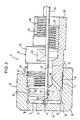
- the piston 2 is used to push out liquid aluminum from a casting cylinder, not shown, of a die casting press.
- the piston 2 has a cap 10 made of a copper alloy which is screwed onto an external thread 6 of a carrier body 8 by means of an internal thread 4.
- the cylinder, not shown, is made of steel and the carrier body 8 is also made of steel.
- the cap 10 lies with an inner cover surface 12 on a front surface 14 of the carrier body 8. It is screwed with its internal thread 4 onto the external thread 6 of the carrier body 8 and shrunk thermally. When cooling, the cap 4 spans the carrier body 8 and is blocked thereby.
- the carrier body 8 has at its end leading to the front surface 14 a tapering towards the front surface 14 towards the conical bevel 16, which is surrounded by an annular recess 18 in the cap 10, so that an annular channel 20 is formed which extends along the circumference of the inner cover surface 12 of the cap 10 and along the circumference of the front surface 14 of the carrier body 8 extends.
- a supply channel for the coolant runs axially through the carrier body 8.
- the carrier body 8 has an axial bore 22, into which a coolant supply tube 24 is inserted and sealed off from the bore 22 next to its outlet end by an annular seal 26 inserted into the bore 22.
- radial channels 28 which connect the mouth of the feed channel 22 in the front surface 14 of the carrier body 8 with the ring channel 20.
- recesses 30 are provided between the radial channels 28, which, together with the jacket of the cap 10, delimit return channels 32 extending from the annular channel 20.
- the recesses 30 and thus the return channels 32 are offset in the circumferential direction from the radial channels 28, so that the coolant is forced to flow through the ring channel 20 in the circumferential direction.
- the return channels 32 open into an annular space 34 between a circumferential shoulder 36 of the carrier body 8 and the jacket of the cap 10. From this annular space 34, channel sections 38 are directed obliquely inwards, which open into a common return channel 40 with an annular cross section.
- This return channel 40 is formed between an inner annular recess 42, the bore 22 of the support body 8 and the tube 24.
- the inner cover surface 12 of the cap 10 has a dome-shaped recess 44.
- the circumference of the carrier body 8 is sealed off from the cap 10 near the end by ring seals 50, 52 which are embedded in the circumference of the carrier body 8.
- the carrier body 8 has an extension 54 behind the cap 10, on which gripping surfaces 60 for a tool are located.
- the rear end of the carrier body 8 consists of a shaft 62 with an external thread 64 which is to be screwed onto a hollow piston rod.
- the carrier body 8 has at its rear end an extension 66 with an internal thread 68 into which a hollow piston rod with an external thread is to be screwed.
- FIG. 3 to 5 show a cap 10 which has a cylindrical projection 102 with an outer ring web 104 on its outer cover surface 100.
- This ring web 104 engages in an inner ring groove 106 of a sealing ring 108.
- the sealing ring 108 is slit radially in steps at a point 110.
- the sealing ring 108 is preferably mounted in such a way that its slot lies on the lower part of the casting cylinder, since the aluminum solidifies there earlier.
- the transition surfaces 112, 114 between the step surfaces 116, 118, 120, 122 lie close together. There are clearances 124, 126 between the step surfaces 116, 120 on the one hand and 118, 122 on the other hand.
- the sealing ring 108 can thus be pulled apart somewhat and pressed together a little without affecting the seal between the transition surfaces 112 and 114.
- the cylindrical extension 102 is provided with an annular recess 103 which serves to receive an inner annular web 109 of the sealing ring 108.
- the sealing ring 108 On both sides of its slot, the sealing ring 108 has axially directed conical holes 142 for the engagement of ends of a collet.
- the sealing ring 108 and the projection 102 have V-shaped opposing boundary surfaces 128, 130 on the front.
- Cap 10 abuts the sealing ring 108.
- the radially inner boundary of the sealing ring 108 facing the outer cover surface 100 of the cap 10 is designed as a run-up slope 134.
- the radially outer boundary of the sealing ring 108 facing the outer cover surface 100 of the cap 10 is designed as a centering run-up bevel 136 which, if it is not required, can also be provided on the casting cylinder.
- the side surface 138 of the ring web 104 facing the cover surface 100 of the cap 10 has grain attachments 140 for engaging grain impacts in the sealing ring 108.
- the chamfer is omitted compared to the embodiment according to FIG. 1.
- the cap 10 is provided with a frustoconical projection 69 on the end face.
- the cap 10 has a section 11 of reduced outer diameter next to the rear boundary surface 111 of the sealing ring 108.
- FIGS. 9 and 10 The embodiment according to FIGS. 9 and 10 is designed accordingly.
- the front boundary surface 13 of the cap 10 projects from the front boundary surface 113 of the sealing ring 108.
- the surfaces 128, 130 run in a wedge shape obliquely to the longitudinal axis of the piston.
- the surface 128 runs axially.
- surface 128 also extends axially.
Landscapes
- Engineering & Computer Science (AREA)
- Mechanical Engineering (AREA)
- Pistons, Piston Rings, And Cylinders (AREA)
- Injection Moulding Of Plastics Or The Like (AREA)
Abstract
Description
- Die Erfindung betrifft einen Kolben, insbesondere für eine Druckgußpresse nach dem Oberbegriff des Anspruchs 1.
- Bekannte Kolben dieser Art weisen eine Kappe auf, deren innere Deckfläche, einen Kühlmittelraum freilassend, in Abstand von der Frontfläche des Trägerkörpers liegt. Die Kappe sitzt mit ihrem hinteren Rand auf einer Ringschulter des Trägerkörpers auf. Zwischen dem Innengewinde der Kappe und einem Ansatz am Trägerkörper, von dem das zugehörige Außengewinde ausgeht, besteht bei aufgeschraubter Kappe ein Spalt. Erfahrungsgemäß lösen sich diese Kappen während des Betriebs verhältnismäßig leicht vom Trägerkörper. Der Kühlmittelraum in der Kappe kühlt überdies die Deckwand der Kappe nicht ausreichend. Das hat zur Folge, daß der Rand der Deckkappe mit großer Kraft an die Innenfläche des Gießzylinders angreift und verschlossen wird. Üblicherweise liegt dabei die momentane Temperatur der Oberfläche der Kappe bei etwa 300°C, während die Temperatur des flüssigen Aluminiums 700°C beträgt. Kühlt sich nach dem Arbeiten die Kappe wieder ab, entsteht ein keilförmiger Spalt zwischen dem Umfangsrand der Deckwand der Kappe, in den flüssiges Aluminium eindringen kann, sich dort verfestigen kann und die Reibung zwischen Kolben und Zylinder erheblich erhöht und dementsprechend auch der Verschleiß.
- Aufgabe der Erfindung ist es, für einen festen Sitz der Kappe auf dem Trägerkörper zu sorgen und den Verschleiß der Kappe möglichst zu mindern.
- Die Lösung dieser Aufgabe ist in Anspruch 1, in einer bevorzugten Ausbildung in Anspruch 2 angegeben.
- Das Aufschrumpfen der Kappe hat zur Folge, daß die Kappe vom Trägerkörper praktisch nicht lösbar ist, wenn sie im ausgebauten Zustand des Kolbens vorher erwärmt wird. Dadurch, daß die innere Deckfläche der Kappe an der Frontfläche des Trägerkörpers anliegt, ist eine großflächige, direkte, axiale Kraftübertragung vom Trägerkörper auf die Kappe möglich, ohne daß das Gewinde und das Gewinde der Kappe belastet werden.
- Dadurch, daß nach Anspruch 2 die Kühlung in erster Linie durch den Ringkanal erfolgt, der sich längs des Umfangs der inneren Stirnfläche der Kappe erstreckt, erfolgt eine besonders wirksame Kühlung des Umfangsrands der Stirnfläche, die verhindert, daß sich die Stirnwand bei Erwärmung stark radial dehnt, so daß die oben erwähnten Mängel nicht auftreten. Als Kühlmittel wird häufig kalkhaltiges Wasser verwendet, aus dem sich Kalk an den wärmsten Stellen in dem Kolben absetzt. Die wärmsten Stellen liegen in der Kappe. Die Kappe ist überdies Verschleißteil und muß gelegentlich ausgewechselt werden. Beim Auswechseln wird zugleich der in der Kappe niedergeschlagene Kalk entfernt.
- Durch die Erfindung wird es möglich, Kappen zu verwenden, die im Vergleich zu bekannten Kappen dünnere Wände aufweisen, was zur Verbesserung der Kühlung und zu erheblicher Materialeinsparung führt.
- Es ist ohne Schwierigkeit möglich, gleichartige Kappen mit unterschiedlichem Durchmesser herzustellen und daher Trägerkörpern unterschiedlichen Durchmessers anzupassen, ohne daß die Kühlwirkung beeinträchtigt wird.
- Die Zuführung des Kühlmittels zum Ringkanal und die Abführung des Kühlmittels vom Ringkanal erfolgt konstruktiv besonders einfach gemäß Anspruch 3. Eine weitere konstruktive Vereinfachung ergibt sich aus Anspruch 4. Um den Strömungswiderstand des Kühlmittels zu mindern, ist bevorzugt eine Ausbildung gemäß Anspruch 5 vorgesehen. Eine besonders hohe Verschleißminderung der Kappe ergibt sich durch die Ausbildung nach Anspruch 6. Die Abfasung nach diesem Anspruch ist besonders empfehlenswert, wenn die Gießkammer gekühlt wird und sichergestellt wird, daß das Aluminium vor der Preßphase erstarrt. Sind diese Voraussetzungen nicht erfüllt, kann die Abfasung entfallen.
- Die Kühlkanäle sind so ausgelegt, daß der Kühlmittelstrom turbulent wird, wodurch sich eine besonders günstige Kühlung ergibt.
- Die Temperatur des Gießzylinders wird mit zunehmendem Füllungsgrad des Gießzylinders und zunehmendem Gewicht des Gießmaterials im Gießzylinder höher. Wird - etwa wegen unterschiedlicher Wärmeausdehnung oder wegen Verschleisses - das Spiel zwischen dem Kolben und dem Gießzylinder größer, so kann flüssiges Aluminium in den Zwischenraum zwischen Kolben und Gießzylinder eindringen und nicht nur die Innenfläche des Gießzylinders beschädigen, sondern auch die Lebensdauer des Kolbens mindern. Um dies zu vermeiden, ist bevorzugt eine Ausbildung nach Anspruch 7 vorgesehen. Der Dichtungsring nach Anspruch 7 verhindert nicht nur das Eindringen des flüssigen Aluminiums in das Spiel zwischen dem Kolben und dem Gießzylinder, sondern verbessert auch die Gußqualität, besonders wenn unter Vakuum gegossen wird. Die für die Erfindung wesentliche optimale Kühlung des Kolbens wird durch den Dichtungsring nicht beeinträchtigt, was Voraussetzung für eine hohe Lebensdauer ist; vielmehr wird auch der Dichtungsring gekühlt.
- Der Dichtungsring kann gemäß Anspruch 8 in an sich bekannter Weise aufgeschrumpft sein.
- Eine vereinfachte Montage und Auswechslung erhält man, wenn der Dichtungsring entsprechend Anspruch 9 geschlitzt ist.
- Die labyrinthartig abdichtende Schlitzung des Dichtungsrings ist bevorzugt so ausgelegt, daß der Dichtungsring, auch wenn er etwas auseinandergezogen wird, stets dicht ist, so daß sich der Dichtungsring auch bei plötzlicher Erhitzung ausdehnen kann, ohne seine Dichtwirkung zu verlieren.
- Der Dichtungsring soll aus einer Legierung mit möglichst großem Abreibewiderstand bestehen, die eine hohe Standzeit hat. Bevorzugt ist eine Legierung gemäß Anspruch 10. Insbesondere kommt dabei eine Legierung gemäß Anspruch 11 in Betracht, wobei der Warmarbeitsstahl nach Anspruch 11 gegen Anfressen einer besonderen Behandlung unterzogen werden kann. Eine andere besonders geeignete Legierung ist in Anspruch 12 angegeben, wobei sich eine Zusammensetzung entsprechend Anspruch 13 besonders bewährt hat.
- Der Dichtungsring in den genannten Ausführungsformen kann nur dank der guten Kühlung des erfindungsgemäßen Kolbens verwendet werden.
- Damit das Aluminium insbesondere in der Endphase eines Gusses den Dichtungsring auf die Innenfläche des Gießzylinders drückt, wodurch die gewünschte Dichtung zwischen Gießzylinder und Kolben erhöht wird, und damit das Aluminium erstarren kann, bevor es in die Ringausnehmung gelangt, ist bevorzugt eine Ausbildung gemäß Anspruch 14 vorgesehen.
- Damit der Dichtungsring einen hohen Preßdruck beim Gießen aufnehmen kann, ist bevorzugt eine Ausbildung gemäß Anspruch 15 vorgesehen.
- Um den Dichtungsring ohne Schwierigkeit montieren zu können, ist bevorzugt eine Ausbildung gemäß Anspruch 16 vorgesehen.
- Um zu erreichen, daß der Dichtungsring stets zentriert bleibt und einem Herausziehen des Kolbens aus dem Gießzylinder nur einen geringen Widerstand entgegensetzt, ist bevorzugt eine Ausbildung nach Anspruch 17 vorgesehen.
- Um den Dichtungsring bei noch nicht montiertem Kolben mit kleinem Durchmesser am Kolben festzuhalten, ist bevorzugt eine Ausbildung nach Anspruch 18 vorgesehen.
- Damit der geschlitzte Dichtungsring leicht montiert und ausgetauscht werden kann, ist er bevorzugt gemäß Anspruch 19 ausgebildet. Bei einer solchen Ausbildung kann der Dichtungsring auch unter Arbeitstemperaturen von 100 bis 300°C in der Gießkammer und der Temperatur entsprechender Ausdehnung der Gießkammer selbst dann während zwei Arbeitszyklen montiert werden, wenn er überdimensioniert ist, was besonders für vollautomatisch arbeitende Gießmaschinen von Bedeutung ist.
- Um bei trotz der Ausbildung des Dichtungsrings durchtretendem flüssigem Aluminium das durchtretende und festwerdende Aluminium auffangen zu können, ist bevorzugt eine Ausbildung gemäß Anspruch 20 vorgesehen. Das durchgetretene festgewordene Aluminium wird bei dieser Ausbildung beim Ausfahren des Kolbens bis zum Öffnen der Form durch Druckluft entfernt. Die Entfernung solcher Aluminiumreste, die zwischen dem Spiel des Kolbens und der Gießkammer haften bleiben, ist von besonderer Bedeutung, weil die Aluminiumreste bei einer Rückbewegung des Kolbens Riefen am Kolben bilden, die einen wesentlichen Beitrag für eine frühzeitige Abnutzung des Kolbens bilden, das Spiel zwischen Kolben und Gießkammer vergrößern und zu einem Klemmen des Kolbens führen können.
- Um eine Beschädigung des Dichtungsrings zu vermeiden, wenn zu wenig oder kein Aluminium vorhanden ist und trotzdem gespritzt wird, ist bevorzugt eine Ausbildung nach Anspruch 21 vorgesehen.
- Durch einen erfindungsgemäß ausgebildeten Dichtungsring werden insbesondere folgende Vorteile erzielt:
- a) Der Verschleiß der Gießkammer wird gemindert.
- b) Die Gußqualität wird erhöht, da Klemmen in der Preßphase unterbunden wird.
- c) Ein Auswechseln des Kolbens ist nicht erforderlich, sondern nur ein Auswechseln des Dichtungsrings, was eine erhebliche Zeitersparnis zur Folge hat.
- d) Da der Dichtungsring schnell montiert werden kann, besteht die Möglichkeit, einen überdimensionierten Dichtungsring zu montieren.
- Die Erfindung wird im folgenden an einem Ausführungsbeispiel unter Hinweis auf die beigefügten Zeichnungen beschrieben, wobei der Kürze wegen nur auf flüssiges Aluminium als Gießmetall Bezug genommen wird.
- Fig. 1 zeigt einen Axialschnitt durch einen Kolben. Die obere Hälfte und die untere Hälfte kennzeichnen etwas verschiedene Ausführungsformen.
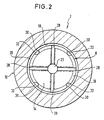
- Fig. 2 zeigt eine Stirnansicht auf den Kolben.
- Fig. 3 zeigt einen Radialschnitt durch eine zweite Ausführungsform einer Kappe mit einem an ihre äußere Deckfläche angesetzten Dichtungsring entsprechend dem Schnitt III-III in Fig. 4.
- Fig. 4 zeigt eine Ansicht in Blickrichtung IV der Fig. 3.
- Fig. 5 zeigt eine Ansicht in Blickrichtung V der Fig. 4.
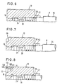
- Fig. 6 zeigt einen Teilradialschnitt durch eine dritte Ausführungsform einer Kappe.
- Fig. 7 zeigt einen Teilradialschnitt durch eine vierte Ausführungsform einer Kappe.
- Fig. 8 zeigt einen Teilradialschnitt durch eine fünfte Ausführungsform einer Kappe.
- Fig. 9 zeigt einen Teilradialschnitt durch eine sechste Ausführungsform einer Kappe.
- Fig. 10 zeigt einen Radialschnitt durch eine siebte Ausführungsform einer Kappe.
- Der Kolben 2 nach dem Ausführungsbeispiel dient zum Hinausdrücken von flüssigem Aluminium aus einem nicht dargestellten Gießzylinder einer Druckgußpresse. Der Kolben 2 weist eine mittels eines Innengewindes 4 auf ein Außengewinde 6 eines Trägerkörpers 8 geschraubte Kappe 10 aus einer Kupferlegierung auf. Der nicht dargestellte Zylinder besteht aus Stahl und auch der Trägerkörper 8 besteht aus Stahl. Die Kappe 10 liegt mit einer inneren Deckfläche 12 an einer Frontfläche 14 des Trägerkörper 8 an. Sie ist mit ihrem Innengewinde 4 auf das Außengewinde 6 des Trägerkörpers 8 aufgeschraubt und thermisch aufgeschrumpft. Bei der Abkühlung umspannt die Kappe 4 den Trägerkörper 8 und wird dadurch blockiert.
- Der Trägerkörper 8 weist an seinem zur Frontfläche 14 führenden Ende eine sich zur Frontfläche 14 hin verjüngende konische Abschrägung 16 auf, die von einer Ringausnehmung 18 in der Kappe 10 umfaßt ist, so daß ein Ringkanal 20 entsteht, der sich längs des Umfangs der inneren Deckfläche 12 der Kappe 10 und längs des Umfangs der Frontfläche 14 des Trägerkörpers 8 erstreckt.
- Ein Zuführungskanal für das Kühlmittel verläuft axial durch den Trägerkörper 8. Hierzu weist der Trägerkörper 8 eine axiale Bohrung 22 auf, in die ein Kühlmittelzuführungsrohr 24 gesteckt und gegenüber der Bohrung 22 nächst ihrem Austrittsende durch eine in die Bohrung 22 eingelassene Ringdichtung 26 abgedichtet ist. In der Frontfläche 14 des Trägerkörpers 8 befinden sich Radialkanäle 28, die die Mündung des Zuführungskanals 22 in der Frontfläche 14 des Trägerkörpers 8 mit dem Ringkanal 20 verbinden. Im Umfang des Trägerkörpers 8 sind zwischen den Radialkanälen 28 Ausnehmungen 30 vorgesehen, die zusammen mit dem Mantel der Kappe 10 von dem Ringkanal 20 ausgehende Rückführungskanäle 32 begrenzen. Die Ausnehmungen 30 und somit die Rückführungskanäle 32 liegen in Umfangsrichtung versetzt zu den Radialkanälen 28, damit das Kühlmittel gezwungen wird, in Umfangsrichtung durch den Ringkanal 20 zu strömen. Die Rückführungskanäle 32 münden in einem Ringraum 34 zwischen einer Umfangsabsetzung 36 des Trägerkörpers 8 und dem Mantel der Kappe 10. Von diesem Ringraum 34 gehen schräg nach innen gerichtete Kanalabschnitte 38 aus, die in einen gemeinsamen, im Querschnitt ringförmigen Rückführungskanal 40 münden. Dieser Rückführungskanal 40 ist zwischen einer inneren Ringausnehmung 42, der Bohrung 22 des Trägerkörpers 8 und dem Rohr 24 ausgebildet.
- Gegenüber der Mündung der Bohrung 22 weist die innere Deckfläche 12 der Kappe 10 eine kalottenförmige Ausnehmung 44 auf.
- Ringsum ist die äußere Deckfläche 46 der Kappe 10 mit einer Abfasung 48 versehen.
- Der Umfang des Trägerkörpers 8 ist gegenüber der Kappe 10 nächst derem Ende mit Ringdichtungen 50, 52 abgedichtet, die in den Umfang des Trägerkörpers 8 eingelassen sind.
- Bei der Ausführungsform entsprechend der oberen Hälfte der Fig. 1 weist der Trägerkörper 8 hinter der Kappe 10 eine Erweiterung 54 auf, an der sich Greifflächen 60 für ein Werkzeug befinden. Das rückwärtige Ende des Trägerkörpers 8 besteht aus einem Schaft 62 mit einem Außengewinde 64, das auf eine hohle Kolbenstange zu schrauben ist.
- Bei der Ausführungsform gemäß der unteren Hälfte der Fig. 1 weist der Trägerkörper 8 an seinem hinteren Ende eine Erweiterung 66 mit einem Innengewinde 68 auf, in das eine hohle Kolbenstange mit einem Außengewinde einzuschrauben ist.
- Die Fig. 3 bis 5 zeigen eine Kappe 10, die auf ihrer äußeren Deckfläche 100 einen zylindrischen Ansatz 102 mit einem äußeren Ringsteg 104 aufweist. Dieser Ringsteg 104 greift in eine innere Ringnut 106 eines Dichtungsrings 108 ein. Der Dichtungsring 108 ist an einer Stelle 110 radial stufenförmig geschlitzt. Bevorzugt wird der Dichtungsring 108 so montiert, daß seine Schlitzung am unteren Teil des Gießzylinders liegt, da das Aluminium dort früher erstarrt. Die Übergangsflächen 112, 114 zwischen den Stufenflächen 116, 118, 120, 122 liegen dicht aneinander. Zwischen den Stufenflächen 116, 120 einerseits und 118, 122 andererseits befinden sich Spielräume 124, 126. Der Dichtungsring 108 kann also etwas auseinandergezogen und etwas zusammengedrückt werden, ohne daß die Dichtung zwischen den Übergangsflächen 112 und 114 beeinflußt wird. Der zylindrische Ansatz 102 ist mit einer Ringausnehmung 103 versehen, die der Aufnahme eines inneren Ringstegs 109 des Dichtungsrings 108 dient. Beidseitig seiner Schlitzung weist der Dichtungsring 108 axial gerichtete konische Löcher 142 zum Eingriff von Enden einer Spannzange auf.
- Der Dichtungsring 108 und der Ansatz 102 weisen frontseitig V-förmig einander gegenüberstehende Begrenzungsflächen 128, 130 auf. An einer durch den Ansatz 102 radial begrenzten Ringschulterfläche 132 der äußeren Deckfläche 100 der Kappe 10 liegt der Dichtungsring 108 an. Die der äußeren Deckfläche 100 der Kappe 10 zugewandte radial innere Begrenzung des Dichtungsrings 108 ist als Auflaufschräge 134 ausgebildet. Die der äußeren Deckfläche 100 der Kappe 10 zugewandte radial äußere Begrenzung des Dichtungsrings 108 ist als zentrierende Auflaufschräge 136 ausgebildet, die, wenn sie entfällt, auch am Gießzylinder vorgesehen sein kann.
- Die der Deckfläche 100 der Kappe 10 zugewandte Seitenfläche 138 des Ringstegs 104 weist Kornansätze 140 zum Eingriff in Korneinschläge im Dichtungsring 108 auf.
- Bei der Ausführungsform nach Fig. 6 ist gegenüber der Ausführungsform nach Fig. 1 die Abfasung weggelassen.
- Bei der Ausführungsform nach Fig. 7 ist die Kappe 10 stirnseitig mit einem stumpfkegeligen Ansatz 69 versehen. Bei der Ausführungsform nach Fig. 8 weist die Kappe 10 nächst der hinteren Begrenzungsfläche 111 des Dichtungsrings 108 einen Abschnitt 11 verringerten Außendurchmessers auf.
- Entsprechend ist die Ausführungsform nach den Fig. 9 und 10 ausgebildet.
- Bei den Ausführungsformen nach den Fig. 8 bis 10 steht die vordere Begrenzungsfläche 13 der Kappe 10 gegenüber der vorderen Begrenzungsfläche 113 des Dichtungsrings 108 vor.
- Bei der Ausführungsform nach Fig. 8 verlaufen die Flächen 128, 130 schräg zur Längsachse des Kolbens keilförmig. Bei der Ausführungsform nach Fig. 9 verläuft die Fläche 128 axial. Bei der Ausführungsform nach Fig. 10 verläuft die Fläche 128 ebenfalls axial.
Claims (21)
dadurch gekennzeichnet,
daß die Kappe (10) mit einer inneren Deckfläche (12) an einer Frontfläche (14) des Trägerkörpers (8) anliegt und mit ihrem Innengewinde (4) thermisch auf das Außengewinde (6) des Trägerkörpers (8) aufgeschraubt und vorzugsweise überdies thermisch aufgeschrumpft ist.
dadurch gekennzeichnet,
daß der Raum im wesentlichen die Form eines Ringkanals (20) hat, der sich längs des Umfangs der inneren Deckfläche (12) der Kappe (10) und der Frontfläche (14) des Trägerkörpers (8) erstreckt.
dadurch gekennzeichnet,
daß sich der Zuführungskanal (22) für das Kühlmittel axial durch den Trägerkörper (8) erstreckt, daß sich in der Frontfläche (14) des Trägerkörpers (8) Radialkanäle (28) befinden, die eine Mündung des Zuführungskanals (22) in der Frontfläche (14) des Trägerkörpers (8) mit dem Ringkanal (20) verbinden und daß im Umfang des Trägerkörpers (8) zwischen den Radialkanälen (28) von dem Ringkanal (20) ausgehende Rückführungskanäle (32) vorgesehen sind.
dadurch gekennzeichnet,
daß sich die Rückführungskanäle (32) über schräg nach innen gerichtete Abschnitte (38) zu einem gemeinsamen, im Querschnitt ringförmigen Rückführungskanal (40) vereinigen, der den Zuführungskanal (22) umschließt.
dadurch gekennzeichnet,
daß die innere Deckfläche (12) der Kappe (10) gegenüber der Mündung des Zuführungskanals (22) eine kalottenförmige Ausnehmung (44) aufweist.
dadurch gekennzeichnet,
daß die äußere Deckfläche der Kappe (10) ringsum mit einer Abfasung (48) versehen ist.
Applications Claiming Priority (2)
| Application Number | Priority Date | Filing Date | Title |
|---|---|---|---|
| DE19893934778 DE3934778A1 (de) | 1988-12-28 | 1989-10-18 | Kolben, insbesondere fuer eine druckgusspresse |
| DE3934778 | 1989-10-18 |
Publications (3)
| Publication Number | Publication Date |
|---|---|
| EP0423413A2 true EP0423413A2 (de) | 1991-04-24 |
| EP0423413A3 EP0423413A3 (en) | 1993-02-17 |
| EP0423413B1 EP0423413B1 (de) | 1997-04-02 |
Family
ID=6391723
Family Applications (1)
| Application Number | Title | Priority Date | Filing Date |
|---|---|---|---|
| EP90102606A Expired - Lifetime EP0423413B1 (de) | 1989-10-18 | 1990-02-09 | Kolben, insbesondere für eine Druckgusspresse |
Country Status (4)
| Country | Link |
|---|---|
| US (1) | US5048592A (de) |
| EP (1) | EP0423413B1 (de) |
| DE (1) | DE59010692D1 (de) |
| ES (1) | ES2102354T3 (de) |
Cited By (7)
| Publication number | Priority date | Publication date | Assignee | Title |
|---|---|---|---|---|
| WO2003074214A1 (de) * | 2002-03-04 | 2003-09-12 | Allper Ag | Dichtring und kolben für einen druckgiesszylinder |
| WO2010084454A1 (en) | 2009-01-21 | 2010-07-29 | Brondolin S.P.A. | Die casting cooled pistons |
| DE202010008596U1 (de) | 2010-09-21 | 2010-12-02 | Schmelzmetall (Deutschland) Gmbh | Druckgusskolben |
| EP2554296A2 (de) | 2011-08-05 | 2013-02-06 | Schmelzmetall AG | Druckgusskolbenkopf |
| CN104625012A (zh) * | 2015-02-04 | 2015-05-20 | 大连鸿森精密模具有限公司 | 一种压铸机的压射头 |
| US9829108B2 (en) | 2009-01-21 | 2017-11-28 | Brondolin S.P.A. | Die casting piston and ring assembly |
| DE102022114210A1 (de) | 2022-06-05 | 2023-12-07 | Gerhard Schoch | Kolbendichtring für einen Druckgießzylinder |
Families Citing this family (28)
| Publication number | Priority date | Publication date | Assignee | Title |
|---|---|---|---|---|
| ES2095886T3 (es) * | 1991-07-29 | 1997-03-01 | Allper Ag | Embolo, particularmente para empujar metal liquido fuera de un cilindro de colada. |
| US5272900A (en) * | 1992-09-18 | 1993-12-28 | Exco Technologies, Limited | Bayonet style connector for metal extrusion dummy block |
| US5311761A (en) * | 1992-09-18 | 1994-05-17 | Exco Technologies, Limited | Metal extrusion dummy block having a spring loaded valve |
| US5687604A (en) * | 1996-05-30 | 1997-11-18 | Exco Technologies Ltd. | Thermal controlled mandrel with replaceable tip for copper and brass extrusion |
| US5918498A (en) * | 1996-07-18 | 1999-07-06 | Robbins; Paul H. | Dummy block construction |
| DE59707737D1 (de) * | 1997-09-09 | 2002-08-22 | Andre Mueller | Kolben für eine Warmkammer-Druckgiessmachine |
| IT250574Y1 (it) | 2000-10-13 | 2003-09-24 | Copromec S R L | Pistone per la pressofusione a camera fredda |
| US6598450B2 (en) * | 2001-11-02 | 2003-07-29 | Sequa Can Machinery, Inc. | Internally cooled punch |
| US7464744B2 (en) * | 2005-09-13 | 2008-12-16 | Peter Manoff | Shot sleeve insert and method of retarding heat erosion within a shot sleeve bore |
| DE102005048717A1 (de) * | 2005-10-12 | 2007-04-19 | Allper Ag | Mehrteiliger Kolben für eine Kaltkammer-Giessmaschine |
| ITBS20060087A1 (it) * | 2006-04-12 | 2007-10-13 | Copromec S R L | Pistone per macchine per la pressofusione a camera fredda |
| ES2321463B1 (es) * | 2006-07-24 | 2010-01-08 | Sergio Walter Fiorito Sarasua | Dispositivo electrico para prensado de latas de aluminio reciclables. |
| US20120111522A1 (en) * | 2010-11-05 | 2012-05-10 | Bullied Steven J | Die casting system machine configurations |
| US9731348B1 (en) | 2012-03-30 | 2017-08-15 | Brunswick Corporation | Method and apparatus for avoiding erosion in a high pressure die casting shot sleeve for use with low iron aluminum silicon alloys |
| US10486229B1 (en) | 2012-03-30 | 2019-11-26 | Brunswick Corporation | Method and apparatus for avoiding erosion in a high pressure die casting shot sleeve for use with low iron aluminum silicon alloys |
| US9757795B1 (en) | 2012-03-30 | 2017-09-12 | Brunswick Corporation | Method and apparatus for avoiding erosion in a high pressure die casting hot sleeve for use with low iron aluminum silicon alloys |
| US9114456B1 (en) | 2012-03-30 | 2015-08-25 | Brunswick Corporation | Method and apparatus for avoiding erosion in a high pressure die casting shot sleeve for use with low iron aluminum silicon alloys |
| US9114455B1 (en) | 2012-03-30 | 2015-08-25 | Brunswick Corporation | Method and apparatus for avoiding erosion in a high pressure die casting shot sleeve for use with low iron aluminum silicon alloys |
| SG194253A1 (en) * | 2012-04-23 | 2013-11-29 | Pratt & Whitney Services Pte Ltd | Shot tube plunger tip portion |
| US20130284018A1 (en) * | 2012-04-30 | 2013-10-31 | Brett Tennar | Screw-on annular rings for die cast beryllium copper plunger tips |
| US8978736B2 (en) * | 2013-03-14 | 2015-03-17 | Crucible Intellectual Property, Llc | Plunger with removable plunger tip |
| TW201501838A (zh) * | 2013-04-04 | 2015-01-16 | Gani Murselaj | 用於金屬模鑄之活塞 |
| RU2016114799A3 (en) * | 2013-10-18 | 2018-06-28 | Exco Technologies Ltd | Wear ring for die-casting piston, die-casting piston incorporating same, and method of forming same |
| WO2018119517A1 (en) | 2016-12-30 | 2018-07-05 | Exco Technologies Limited | Die-casting piston, and die-casting apparatus incorporating same |
| WO2020022304A1 (ja) * | 2018-07-26 | 2020-01-30 | 株式会社Moresco | バックスプレーシステムおよび注入ピストン |
| CN109382496B (zh) * | 2018-12-28 | 2024-01-23 | 中信戴卡股份有限公司 | 冲头总成及包括该冲头总成的压铸机 |
| DE202021001237U1 (de) * | 2021-04-01 | 2021-06-07 | Kornelia Jahn | Druckgießkolben für eine Gießmaschine |
| DE102024122724B3 (de) * | 2024-08-08 | 2025-11-20 | Oskar Frech Gmbh + Co. Kg | Gießkolben für eine Gießmaschine |
Family Cites Families (12)
| Publication number | Priority date | Publication date | Assignee | Title |
|---|---|---|---|---|
| US1326692A (en) * | 1918-12-09 | 1919-12-30 | Theodore Rogatchoff | Method of shrinking bull-rings on pistons. |
| DE1191934B (de) * | 1957-01-23 | 1965-04-29 | Nat Lead Co | Verfahren zum Herstellen von Druckgussteilen mittels Kaltkammerdruckgiessmaschinen |
| US3046621A (en) * | 1958-11-17 | 1962-07-31 | Glen R Morton | Die casting machine plunger tip |
| DE2233132B2 (de) * | 1972-07-06 | 1974-08-01 | Fa. Hugo Kunz, 7443 Frickenhausen | Druckkolben für eine Druckgießmaschine |
| SE7510628L (sv) * | 1974-09-28 | 1976-03-29 | Hugo Kunz | Tryckkolv for en tryckgjutmaskin |
| JPS5768257A (en) * | 1980-10-17 | 1982-04-26 | Toyota Motor Corp | Injector for die casting |
| SU1080922A1 (ru) * | 1982-10-15 | 1984-03-23 | Yagin Vasilij P | Прессующий поршень машины лить под давлением |
| DE3305594C1 (de) * | 1983-02-18 | 1984-07-19 | Friedrich 8192 Geretsried Glas | Giesskolben fuer Druckgiessmaschinen |
| US4886107A (en) * | 1986-02-28 | 1989-12-12 | Zecman Kenneth P | Piston for cold chamber |
| US4667729A (en) * | 1986-02-28 | 1987-05-26 | Zecman Kenneth P | Shot tip for cold chamber die casting machine |
| US4842039A (en) * | 1988-06-27 | 1989-06-27 | Otto Kelm | Self-aligning plunger tip |
| US4899804A (en) * | 1989-02-21 | 1990-02-13 | Hammerer Norman L | Plunger tip for cold chamber die cast machine |
-
1990
- 1990-02-09 US US07/477,072 patent/US5048592A/en not_active Expired - Lifetime
- 1990-02-09 EP EP90102606A patent/EP0423413B1/de not_active Expired - Lifetime
- 1990-02-09 DE DE59010692T patent/DE59010692D1/de not_active Expired - Fee Related
- 1990-02-09 ES ES90102606T patent/ES2102354T3/es not_active Expired - Lifetime
Cited By (12)
| Publication number | Priority date | Publication date | Assignee | Title |
|---|---|---|---|---|
| WO2003074214A1 (de) * | 2002-03-04 | 2003-09-12 | Allper Ag | Dichtring und kolben für einen druckgiesszylinder |
| WO2003074211A3 (de) * | 2002-03-04 | 2004-06-10 | Allper Ag | Kolben für eine kaltkammer-druckgiessmaschine |
| WO2010084454A1 (en) | 2009-01-21 | 2010-07-29 | Brondolin S.P.A. | Die casting cooled pistons |
| US9550233B2 (en) | 2009-01-21 | 2017-01-24 | Brondolin S.P.A. | Die casting cooled pistons |
| US9829108B2 (en) | 2009-01-21 | 2017-11-28 | Brondolin S.P.A. | Die casting piston and ring assembly |
| DE202010008596U1 (de) | 2010-09-21 | 2010-12-02 | Schmelzmetall (Deutschland) Gmbh | Druckgusskolben |
| EP2431112A1 (de) | 2010-09-21 | 2012-03-21 | Schmelzmetall AG | Druckgusskolben |
| EP2554296A2 (de) | 2011-08-05 | 2013-02-06 | Schmelzmetall AG | Druckgusskolbenkopf |
| DE102011052446A1 (de) | 2011-08-05 | 2013-02-07 | Schmelzmetall Ag | Druckgusskolbenkopf |
| CN104625012A (zh) * | 2015-02-04 | 2015-05-20 | 大连鸿森精密模具有限公司 | 一种压铸机的压射头 |
| CN104625012B (zh) * | 2015-02-04 | 2016-09-28 | 大连鸿森精密模具有限公司 | 一种压铸机的压射头 |
| DE102022114210A1 (de) | 2022-06-05 | 2023-12-07 | Gerhard Schoch | Kolbendichtring für einen Druckgießzylinder |
Also Published As
| Publication number | Publication date |
|---|---|
| US5048592A (en) | 1991-09-17 |
| DE59010692D1 (de) | 1997-05-07 |
| ES2102354T3 (es) | 1997-08-01 |
| EP0423413B1 (de) | 1997-04-02 |
| EP0423413A3 (en) | 1993-02-17 |
Similar Documents
| Publication | Publication Date | Title |
|---|---|---|
| EP0423413A2 (de) | Kolben, insbesondere für eine Druckgusspresse | |
| DE3934778A1 (de) | Kolben, insbesondere fuer eine druckgusspresse | |
| DE2945249A1 (de) | Auswechselbare zylinderlaufbuechse | |
| DE2227501A1 (de) | Gleitschiebervorrichtung zum verschliessen bodenseitiger ausgussoeffnungen an giessgefaessen | |
| EP0255475B1 (de) | Füllbüchse für Druckgiessmaschinen | |
| EP0281515B1 (de) | Vorrichtung zum Kühlen einer Leichtmetall-Strangpresse | |
| EP1483074B1 (de) | Dichtring und kolben für einen druckgiesszylinder | |
| DE2613059A1 (de) | Kolben fuer verbrennungsmotoren | |
| CH617610A5 (en) | Horizontal continuous casting machine for metals | |
| DE202010004934U1 (de) | Kolben für eine Kaltkammer-Gießmaschine | |
| DE1097210B (de) | Kolben fuer Brennkraftmaschinen | |
| EP1635973B1 (de) | Kolben für eine kaltkammer-druckgiessmaschine | |
| DE4002263C2 (de) | Kolben-Zylindereinheit | |
| DE4230080C2 (de) | Druckgießkolben, insbesondere für Kaltkammer-Druckgießmaschinen | |
| DE3129602C1 (de) | Vorrichtung zum Annippeln einer Graphitelektrode an eine Dauerelektrode eines Elektroofens | |
| DE69002129T2 (de) | Vorrichtung zum Stranggiessen von flüssigem Metall zwischen zwei Zylindern. | |
| DE19847865C2 (de) | Zylinderlaufbuchse | |
| WO2006042597A1 (de) | Abstichrohr für ein metallurgisches schmelzgefäss | |
| DE2904883C2 (de) | Druckkolben für Druckgießmaschinen | |
| DE1265924B (de) | Stranggiesskokille | |
| DE4019076A1 (de) | Druckgiesskolben | |
| DE1104124B (de) | Verfahren zum Zufuehren des Gleitmittels in eine Kokille mit horizontal liegender Achse zum kontinuierlichen Giessen von Metallen | |
| EP0901852B1 (de) | Kolben für eine Warmkammer-Druckgiessmachine | |
| DE873185C (de) | Kolben, insbesondere fuer Brennkraftmaschinen | |
| EP0710166B1 (de) | Anordnung zur verbindung einer stopfenstange für ein metallurgisches gefäss mit ihrer hebevorrichtung und für die anordnung geeignete stopfenstange sowie verfahren zur herstellung der anordnung |
Legal Events
| Date | Code | Title | Description |
|---|---|---|---|
| PUAI | Public reference made under article 153(3) epc to a published international application that has entered the european phase |
Free format text: ORIGINAL CODE: 0009012 |
|
| AK | Designated contracting states |
Kind code of ref document: A2 Designated state(s): CH DE ES FR GB IT LI SE |
|
| PUAL | Search report despatched |
Free format text: ORIGINAL CODE: 0009013 |
|
| AK | Designated contracting states |
Kind code of ref document: A3 Designated state(s): CH DE ES FR GB IT LI SE |
|
| 17P | Request for examination filed |
Effective date: 19930804 |
|
| 17Q | First examination report despatched |
Effective date: 19940615 |
|
| ITCL | It: translation for ep claims filed |
Representative=s name: JACOBACCI CASETTA & PERANI S.P.A. |
|
| GRAG | Despatch of communication of intention to grant |
Free format text: ORIGINAL CODE: EPIDOS AGRA |
|
| GRAH | Despatch of communication of intention to grant a patent |
Free format text: ORIGINAL CODE: EPIDOS IGRA |
|
| GRAH | Despatch of communication of intention to grant a patent |
Free format text: ORIGINAL CODE: EPIDOS IGRA |
|
| GRAA | (expected) grant |
Free format text: ORIGINAL CODE: 0009210 |
|
| AK | Designated contracting states |
Kind code of ref document: B1 Designated state(s): CH DE ES FR GB IT LI SE |
|
| ITF | It: translation for a ep patent filed | ||
| REG | Reference to a national code |
Ref country code: CH Ref legal event code: EP Ref country code: CH Ref legal event code: NV Representative=s name: A. BRAUN, BRAUN, HERITIER, ESCHMANN AG PATENTANWAE |
|
| GBT | Gb: translation of ep patent filed (gb section 77(6)(a)/1977) |
Effective date: 19970403 |
|
| REF | Corresponds to: |
Ref document number: 59010692 Country of ref document: DE Date of ref document: 19970507 |
|
| ET | Fr: translation filed | ||
| REG | Reference to a national code |
Ref country code: ES Ref legal event code: FG2A Ref document number: 2102354 Country of ref document: ES Kind code of ref document: T3 |
|
| PLBE | No opposition filed within time limit |
Free format text: ORIGINAL CODE: 0009261 |
|
| STAA | Information on the status of an ep patent application or granted ep patent |
Free format text: STATUS: NO OPPOSITION FILED WITHIN TIME LIMIT |
|
| 26N | No opposition filed | ||
| REG | Reference to a national code |
Ref country code: GB Ref legal event code: IF02 |
|
| PGFP | Annual fee paid to national office [announced via postgrant information from national office to epo] |
Ref country code: ES Payment date: 20080228 Year of fee payment: 19 Ref country code: CH Payment date: 20080215 Year of fee payment: 19 |
|
| PGFP | Annual fee paid to national office [announced via postgrant information from national office to epo] |
Ref country code: SE Payment date: 20080214 Year of fee payment: 19 Ref country code: IT Payment date: 20080220 Year of fee payment: 19 Ref country code: GB Payment date: 20080220 Year of fee payment: 19 Ref country code: DE Payment date: 20071115 Year of fee payment: 19 |
|
| REG | Reference to a national code |
Ref country code: CH Ref legal event code: PFA Owner name: ALLPER AG Free format text: ALLPER AG#INDUSTRIEZENTRUM 2000/BP 12, BONNSTRASSE 26#CH-3186 DUEDINGEN (CH) -TRANSFER TO- ALLPER AG#INDUSTRIEZENTRUM 2000/BP 12, BONNSTRASSE 26#CH-3186 DUEDINGEN (CH) |
|
| PGFP | Annual fee paid to national office [announced via postgrant information from national office to epo] |
Ref country code: FR Payment date: 20080214 Year of fee payment: 19 |
|
| REG | Reference to a national code |
Ref country code: CH Ref legal event code: PL |
|
| EUG | Se: european patent has lapsed | ||
| GBPC | Gb: european patent ceased through non-payment of renewal fee |
Effective date: 20090209 |
|
| PG25 | Lapsed in a contracting state [announced via postgrant information from national office to epo] |
Ref country code: CH Free format text: LAPSE BECAUSE OF NON-PAYMENT OF DUE FEES Effective date: 20090228 Ref country code: LI Free format text: LAPSE BECAUSE OF NON-PAYMENT OF DUE FEES Effective date: 20090228 |
|
| REG | Reference to a national code |
Ref country code: FR Ref legal event code: ST Effective date: 20091030 |
|
| PG25 | Lapsed in a contracting state [announced via postgrant information from national office to epo] |
Ref country code: DE Free format text: LAPSE BECAUSE OF NON-PAYMENT OF DUE FEES Effective date: 20090901 |
|
| REG | Reference to a national code |
Ref country code: ES Ref legal event code: FD2A Effective date: 20090210 |
|
| PG25 | Lapsed in a contracting state [announced via postgrant information from national office to epo] |
Ref country code: GB Free format text: LAPSE BECAUSE OF NON-PAYMENT OF DUE FEES Effective date: 20090209 Ref country code: FR Free format text: LAPSE BECAUSE OF NON-PAYMENT OF DUE FEES Effective date: 20090302 |
|
| PG25 | Lapsed in a contracting state [announced via postgrant information from national office to epo] |
Ref country code: ES Free format text: LAPSE BECAUSE OF NON-PAYMENT OF DUE FEES Effective date: 20090210 |
|
| PG25 | Lapsed in a contracting state [announced via postgrant information from national office to epo] |
Ref country code: IT Free format text: LAPSE BECAUSE OF NON-PAYMENT OF DUE FEES Effective date: 20090209 |
|
| PG25 | Lapsed in a contracting state [announced via postgrant information from national office to epo] |
Ref country code: SE Free format text: LAPSE BECAUSE OF NON-PAYMENT OF DUE FEES Effective date: 20090210 |