EP0425689B1 - Verfahren zur rotationssteuerung einer hauptwelle - Google Patents
Verfahren zur rotationssteuerung einer hauptwelle Download PDFInfo
- Publication number
- EP0425689B1 EP0425689B1 EP90906348A EP90906348A EP0425689B1 EP 0425689 B1 EP0425689 B1 EP 0425689B1 EP 90906348 A EP90906348 A EP 90906348A EP 90906348 A EP90906348 A EP 90906348A EP 0425689 B1 EP0425689 B1 EP 0425689B1
- Authority
- EP
- European Patent Office
- Prior art keywords
- spindles
- rotational
- speed
- spindle
- control
- Prior art date
- Legal status (The legal status is an assumption and is not a legal conclusion. Google has not performed a legal analysis and makes no representation as to the accuracy of the status listed.)
- Expired - Lifetime
Links
Images


Classifications
-
- G—PHYSICS
- G05—CONTROLLING; REGULATING
- G05B—CONTROL OR REGULATING SYSTEMS IN GENERAL; FUNCTIONAL ELEMENTS OF SUCH SYSTEMS; MONITORING OR TESTING ARRANGEMENTS FOR SUCH SYSTEMS OR ELEMENTS
- G05B19/00—Program-control systems
- G05B19/02—Program-control systems electric
- G05B19/18—Numerical control [NC], i.e. automatically operating machines, in particular machine tools, e.g. in a manufacturing environment, so as to execute positioning, movement or co-ordinated operations by means of program data in numerical form
- G05B19/416—Numerical control [NC], i.e. automatically operating machines, in particular machine tools, e.g. in a manufacturing environment, so as to execute positioning, movement or co-ordinated operations by means of program data in numerical form characterised by control of velocity, acceleration or deceleration
-
- G—PHYSICS
- G05—CONTROLLING; REGULATING
- G05B—CONTROL OR REGULATING SYSTEMS IN GENERAL; FUNCTIONAL ELEMENTS OF SUCH SYSTEMS; MONITORING OR TESTING ARRANGEMENTS FOR SUCH SYSTEMS OR ELEMENTS
- G05B2219/00—Program-control systems
- G05B2219/30—Nc systems
- G05B2219/50—Machine tool, machine tool null till machine tool work handling
- G05B2219/50234—Synchronize two spindles, axis, electronic transmission, line shafting
-
- G—PHYSICS
- G05—CONTROLLING; REGULATING
- G05B—CONTROL OR REGULATING SYSTEMS IN GENERAL; FUNCTIONAL ELEMENTS OF SUCH SYSTEMS; MONITORING OR TESTING ARRANGEMENTS FOR SUCH SYSTEMS OR ELEMENTS
- G05B2219/00—Program-control systems
- G05B2219/30—Nc systems
- G05B2219/50—Machine tool, machine tool null till machine tool work handling
- G05B2219/50387—Two chucks, grippers, feeder bar, transfer workpiece from one to other
Definitions
- the present invention relates to a spindle rotation control method applied to a machine having two spindles, and more particularly, to a spindle rotation control method for driving the spindles at the same rotational speed with the same rotational phase.
- the workpiece When a workpiece having an anisotropic configuration with respect to the axis thereof is gripped by the second chuck, the workpiece can collide with the second chuck, if the rotational phases (rotational angle positions) of the chucks are different from each other, even though these chucks are rotated at the same speed. In this case, the workpiece can be damaged or deformed.
- US-A-3,997,828 discloses a method of effecting relative angular displacement between two rotary elements until respective marks on the peripheries of the rotary elements are substantially angularly coincident.
- the two rotary elements are a scanning cylinder and a printing form cylinder in a photogravure printing machine, and the two cylinders are brought into the same rotational phase as one another by detecting the angular offset between the marks on their peripheries and increasing the angular velocity of one of the cylinders until the respective marks are angularly coincident.
- a spindle rotation control method comprising the steps of: (a) controlling rotation speeds of first and second spindles of a machine such that the first and second spindles are rotated at a same rotational speed; (b) detecting rotational positions of the first and second spindles; (c) generating a one-revolution signal when the rotational positions detected in said step (b) for each of the first and second spindles assume a predetermined rotational position; and (d) bringing the first and second spindles into the same rotational phase as one another; characterised by: (e) detecting first and second rotational-angle amounts measured from points in time at which the one revolution signals for the first and second spindles are respectively generated in said step (c); (f) reducing the rotational speeds of the first and second spindles in accordance with the first and second rotational-angle amounts detected in said step (e) in such a manner as to cause the first and second spindles to be rotated at the same phase as one another; and (g)
- speed control for the first and second spindles is performed so that both the spindles are rotated at the same rotational speed, and then the rotational speeds of these spindles are decreased in accordance with the first and second rotational quantities measured from the time points at which the one-revolution signals for the spindles are respectively generated. Accordingly, a deviation between rotational phases of the spindles can be eliminated. After the rotational speeds of the first and second spindles are decreased so that the rotational phase deviation between the spindles is eliminated, speed control is performed again such that the spindles are rotated at the same speed. This makes it possible to rotate the spindles at the same rotational speed with the same rotational phase.
- a lathe which is controlled by a spindle rotation control unit for embodying a method of a first embodiment of the present invention, comprises a first and second spindles 10 and 20.
- a first gripping section having a first chuck 11 for gripping a workpiece 30, is coupled to one end of the first spindle 10 for rotation in unison with the spindle.
- a first position coder 12 which generates one pulse each time the first spindle is rotated through a predetermined rotational angle (for example, 4096 pulses per one revolution of the spindle), and which generates a one-revolution signal each time the first spindle assumes a predetermined rotational position.
- a first spindle motor 13 is operatively coupled to the first spindle 10 through a first transmission means 14 composed of a pair of gears, for instance.
- the arrangement on the side of the second spindle 20 is substantially the same as that on the side of the first spindle 10.
- Reference numerals 21 - 24 indicate elements respectively corresponding to the elements 11 - 14.
- the spindle rotation control unit is operated under the control of a host control apparatus, e.g., a numerical control apparatus (NC apparatus) 40 in either one of an independent rotation mode where the first and second spindle motors 13, 23 are rotated, generally, at different speeds, and a synchronous rotation mode where both the motors are rotated at the same speed.
- the spindle rotation control unit is provided with a first and second spindle control circuits 100 and 200 which have substantially the same arrangement and which are respectively composed of microprocessors, etc.
- the microprocessor (hereinafter referred to as first processor) forming the first control circuit 100 is functionally provided with a position control section 110, a speed control section 120, first to third transducer sections 130, 140 and 150, and first to eighth switches 161 - 168.
- the microprocessor (hereinafter referred to as second processor) forming the second control circuit 200 is also provided with similar functional elements 210, 220, 230, 240, 250 and 261 - 268.
- the first and second processors are arranged to execute position and speed control loop processing, etc., on a software basis, so as to achieve the functions of the aforesaid various elements.
- the first control circuit 100 includes the position control section 110 having a position deviation counter 111, a position counter 112 connected to the first position coder 12 for counting output pulses therefrom, a latch circuit 113 connected to the position coder 12 for storing a count value of the position counter 112 at an instant at which a one-revolution signal is generated, and a calculation circuit 114 connected to the elements 112, 113 for calculating a spindle rotational angle measured from that time point at which the one-revolution signal is generated.
- the first and second transducer sections 130, 140 are arranged to convert, in accordance with the following equations (1) and (2), a speed command supplied from the NC apparatus 40 into a first speed command and a first position deviation quantity, which are employed in the synchronizing control mode.
- the third transducer section 150 is arranged to convert the speed command from the NC apparatus 40 into a first moving command for the synchronizing control mode.
- First Speed Command Speed Command x 60 x Gear Ratio Itp Period x 4096 where a value of the first speed command represents the rotational speed per minute, and the itp period represents a speed command delivery period (pulse distribution period) of the NC apparatus 40, and the gear ratio represents a gear ratio between a pair of gears in case that the first transmitting means 14 is composed of these gears.
- the numerical value of "4096" represents the total number of pulses sent from the first position coder 12 during one revolution of the first spindle 10, and the numerical value "60” represents a constant for converting the unit of time from minute to second.
- First Position Deviation Quantity Speed Command Itp Period x Position Gain where the first position deviation quantity is represented by the number of pulses, and the position gain represents a position control gain in the position control section 110 of the first control circuit 100.
- the input sides of the first to third transducer sections 130, 140 and 150 are connected to the NC apparatus 40.
- the output side of the first transducer section 130 is connected to the speed control section 120 through the second and third switches 162 and 163.
- the output side of the second transducer section 140 is connected to the position deviation counter 111 through the seventh switch 167.
- the output side of the third transducer section 150 is connected through the fourth switch 164 to a positive input terminal of an adder having a negative input terminal thereof connected to the position counter 112 and an output terminal thereof connected to the position deviation counter 111 through the fifth switch 165.
- the position deviation counter 111 is connected to the spindle rotational-angle calculation circuit 114 through the sixth switch 166.
- the NC apparatus 40 is connected to the speed control section 120 through the first and third switches 161, 163.
- the second spindle control circuit 200 is constructed in the same manner as the first spindle control circuit 100, and hence a detailed description thereof will be omitted.
- each of the first and second processors of the spindle control unit executes initial setting. That is, a first flag F1 is reset to a value of "0" representing that the synchronizing control mode is not selected, a second flag F2 is reset to a value of "0” representing that the synchronous rotational speed is not reached, and a third flag F3 is reset to a value of "0" representing that a phase synchronizing control command is not delivered.
- both the processors repeatedly execute spindle control processing shown in Figs. 3 and 4 at intervals of the itp period.
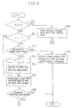
- each of the first and second processors determines whether or not the second flag F2 has a value of "1" representing that the synchronous rotational speed is reached (step S1). If it is determined that the value of the second flag F2 is not “1”, a determination is made as to whether or not the first flag F1 has a value of "1" representative of the synchronizing control mode (step 2). If it is determined that the first flag F1 has not the value "1" representative of the synchronizing control mode, a determination is made as to whether a synchronizing control command is supplied from the NC apparatus 40 (step 3). If such command is not supplied, the first and second processors operate in the independent control mode, so as to independently control the drive of the first and second spindle motors 13, 23 (step 4).
- the first processor closes the first and third switches 161, 163, opens the other switches 162 and 164 - 168, and resets the position deviation counter 111 to a value of "0".
- the speed command for the current itp period is supplied from the NC apparatus 40 to the first processor serving as the speed control section 120.
- the first processor executes the conventionally known speed-control loop processing for the first spindle motor 13.
- a rotational force of the first spindle motor 13 is transmitted to the first spindle 10 through the first transmission means 14, so that the first spindle is rotated.
- the second processor operates in a similar manner, to thereby rotate the second spindle 20.
- the first and second processors respectively serving as the speed control sections 120, 220 are periodically supplied, in general, with different speed commands from the NC apparatus 40.
- both the processors periodically and independently execute the steps S1 - S4 of Fig. 3, to control the drive of the first and second spindle motors 13, 23 so that the first and second spindles 10, 20 are rotated at different rotational speeds.
- the first processor determines this at the step S3 in the itp period immediately after the delivery of the same command. Then, the processor sets the first flag F1 to the value of "1" (step S5), turns off the first switches 161, 261, and turns on the second switches 162, 262. As a result, the operation mode of the spindle control unit is switched from the independent control mode to the synchronizing control mode.
- the first processor calculates the first speed command in accordance with equation (1) given above, and stores the thus calculated speed command into a first register (not shown) built in this processor (step S6). Then, the first processor serving as the speed control section 120 executes the speed control loop processing on the basis of the first speed command supplied through the switches 162, 163 (step S7). Further, the processor determines whether or not the rotational speed of the first spindle 10 reaches the synchronous rotational speed (step S8). If the synchronous rotational speed is not reached, the processing for the current itp period is completed.
- the second processor serving as the speed control section 220 operates in the same manner as in the case of the first processor.
- the rotational speeds of the first and second spindles 10, 20 gradually change toward the synchronous rotational speed.
- both the spindles reach the synchronous rotational speed (more strictly, rotational speeds falling within a predetermined rotational-speed region including the synchronous rotational speed and set beforehand by using an allowable error).
- each of the first and second processors sets the second flag F2 to the value "1" (step S10).
- the processors serving as the second transducer sections 140 and 240, calculate the first and second position deviation quantities which correspond to the synchronous rotational speed.
- the seventh switches 167, 267 are closed for a short period of time, so as to store the calculated quantities to the position deviation counters 111, 211 (step S11).
- the second and third switches 162, 163 (262, 263) are opened, and the fourth, fifth and eighth switches 164, 165 and 168 (264, 265 and 268) are closed.
- the first and second processors serving as the third transducer sections 150, 250 convert the speed command for the current itp period supplied from the NC apparatus 40 into the first and second moving commands, and store these moving commands in their built-in second registers (not shown), respectively (step S12).
- the first and second moving commands for the current itp period are supplied from the second registers through the fourth switches 164, 264 to the positive input terminals of the position deviation counters 111, 211.
- these counters are supplied at their negative input terminals from the position counters 112, 212 with the rotational quantities of the first and second spindles 10, 20 for the current itp period.
- the first and second processors serving as the position control sections 110, 210 execute the position control loop processing on the basis of the first and second moving commands and the first and second spindle rotational quantities, respectively (step S13).
- the position control loop outputs are supplied to the speed control sections 120, 220 through the eighth switch 168, 268.
- the first and second processors serving as these speed control sections execute the speed control loop processing based on the position control loop outputs (speed commands) (step S13).
- the spindles 10 and 20 are rotated at the same synchronous rotational speed, with these spindles subjected to the position control.
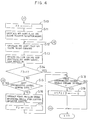
- each of the first and second processors determines whether or not the third flag F3 has a value of "1" representing that the phase synchronizing control command has been sent (step S14). If the value of the third flag F3 is not "1", a determination is made as to whether or not the phase synchronizing control command is supplied from the NC apparatus 40 (step S15). If such command is not supplied, the processing for the current itp period is completed.
- the first processor enters the step S9 to cause built-in third and fourth registers (not shown) to store the current value of the position counter 112 representing the rotational position of the first spindle 10, and the value of the latch circuit 113 representing the first-spindle rotational position at an instant at which the one-revolution signal is generated, respectively. Then, the first processor executes the steps S12 - S15.
- the second processor operates in the same manner.
- the first processor determines this at the step S15 in the itp period immediately after the delivery of the same command.
- the first processor serving as the calculation circuit 114 subtracts the value of the latch circuit 113 from the current value of the position counter 112, so as to calculate a current rotational phase (first spindle rotational-angle quantity measured from an instant at which the one-revolution signal is generated) of the first spindle 10.
- the second processor also calculates a current rotational phase of the second spindle 20.
- both the processors close the sixth switches 166 and 266, and subtracts the calculated values of the first and second spindle rotational phases from the position deviation counters 111 and 211, respectively (step S16).
- the rotational speeds of both the spindles decrease such that the one-revolution signals for the first and second spindles 10 and 20 occur at the same time point, in other words, such that the rotational phases of both the spindles are in agreement with each other (refer to Fig. 2).
- the processors set the third flag F3 to the value "1" which represents that the phase synchronizing control command has been sent (step S17), and determine whether or not a phase synchronizing control release command is supplied from the NC apparatus 40 (step S18). If the release command is not supplied, the processing for the current itp period is completed.
- the steps S1, S9 and S12 - S14 are repeatedly executed.
- the first and second moving commands which correspond to the synchronous rotational speed command supplied from the NC apparatus 40, are supplied to the position deviation counters 111 and 112, respectively.
- the rotational speeds of the first and second spindles 10 and 20 are returned to the synchronous rotational speed, e.g., at the time point of t4 in Fig. 2. At this time, both the spindles are rotated with the same phase.
- both the processors determine this at the step S18 in the itp period immediately after the delivery of the same command, and resets the first to third flaps F1 - F3 to a value of "0" (step S19).
- the speed control in the independent control mode is executed in accordance with the speed command supplied from the NC apparatus 40 (steps S1 - S4).
- the method of the second embodiment is basically the same as that of the first embodiment.
- a spindle rotation control unit (not shown) for embodying the method of the second embodiment is substantially the same in construction as the unit shown in Fig. 1, and is arranged to execute substantially the same control processing as the spindle rotation control processing shown in Figs. 3 and 4.
- Fig. 1 will be referred to for convenience.
- a primary feature of the method of the second embodiment resides in the provision of a step for discriminating the completion of control for synchronizing the rotational phases of the first and second spindles with each other.
- a processor hereinafter referred to as PMC processor
- PMC processor built in the programmable machine controller provided on the side of the NC apparatus 40
- the first and second processors of the spindle rotation control unit are arranged to execute, prior to execution of the step S1 of Fig.
- the calculation circuits 113, 213 of the spindle rotation control unit are connected to the NC apparatus 40 through wires, not shown in Fig. 1.
- the PMC processor performs initial setting. That is, the PMC processor resets a fourth flag Ff to a value of "0" which represents that the phase synchronizing control command is not supplied, and resets a fifth flag F5 to a value of "0" which represents that the synchronizing control command is not supplied. Then, the PMC processor repeatedly executes the discrimination processing shown in Fig. 5 at intervals of the itp period.
- the PMC processor determines whether or not the fourth flag Ff has the value "1" indicating that the phase synchronizing control command has been supplied (step S100). If the value of the fourth flag Ff is not "1", a determination is made as to whether or not a fifth flag Fs has a value of "1" representing that the synchronizing control command has been supplied (step S101). If the value of the fifth flag Fs is not "1", the PMC processor further determines whether the synchronizing control command has been supplied (step S102). If the same command is not inputted as yet, the processing for the current itp period is completed. In this case, the first and second processors of the spindle rotation control unit execute the speed control loop processing (corresponding to the step S4 in Fig. 3), in accordance with the speed command from the NC apparatus 40.
- the PMC processor determines this at the step S102 in the itp period immediately after the input of the same command, and sets the value of the fifth flag Fs to "1" (step S103). Further, the PMC processor delivers the synchronizing control command and the synchronous rotational speed command to the spindle rotation control unit (step S104). In response to this, the first and second processors of the spindle rotation control unit execute the speed control loop processing (corresponding to the step S7 in Fig. 3) in accordance with the first and second speed commands calculated on the basis of the synchronous rotational speed command from the PMC processor.
- the PMC processor determines whether or not the phase synchronizing control command is supplied (step S105). If the command is not supplied, the processing for the current itp period is completed. In the next and later itp periods, the PMC processor executes the steps S100, S101 and S105, and then waits the input of the phase synchronizing control command.
- the PMC processor determines this at the step S105 in the itp period immediately after the input of the same command, sets the fourth flag Ff to the value "1" which represents the input of the phase synchronizing control command (step S106), and delivers this command to the spindle rotation control unit (step S107).
- the first and second processors of the spindle rotation control unit execute processing (corresponding to the step S16 in Fig. 4) by which the rotational quantities ⁇ 1 and ⁇ 2 measured from time points at which the one-revolution signals for the first and second spindles 10 and 20 are generated are subtracted from the position deviation counters 111 and 211, respectively.
- the PMC processor receives the rotational quantities ⁇ 1, ⁇ 2 of the first and second spindles 10 and 20 delivered from the first and second processors (step S108), and determines whether or not the absolute value
- the PMC processor When it is determined at the step S109 in a certain itp period that the absolute value
- the present invention is not limited to the first and second embodiments mentioned above, and various modifications thereof may be made.
- the completion of the rotational phase synchronizing control is determined when the absolute value
- completion of the rotational phase synchronizing control may be determined when the absolute value of the difference between stored values of the position deviation counters 111, 211 becomes equal to or less than an allowable value.
- both the position deviation counter values become identical with each other, if the rotational phases of the spindles are the same with each other at an instant at which the rotational speeds of the spindles are returned to the synchronizing rotational speed after the decelerating operation of the first and second spindles.
- the synchronizing control command and the phase synchronizing control command are inputted manually.
- the synchronizing rotation completing signal is sent from each of the first and second processors when it is determined at the step S8 of Fig. 3 that the synchronous rotational speed is reached, and the phase synchronizing control command is sent to the spindle rotation control unit from the PMC processor when the supply of the same signals from both the processors is completed.
- the aforementioned shift between the workpiece gripping states (operation of changing the gripped side) in the lathe, etc., to which the present invention is applied may be made in response to the phase synchronizing control completion signal supplied from the PMC processor. Further, a message indicating permission of the workpiece gripping state shift may be displayed when the phase synchronizing control completion signal is generated.
Landscapes
- Engineering & Computer Science (AREA)
- Human Computer Interaction (AREA)
- Manufacturing & Machinery (AREA)
- Physics & Mathematics (AREA)
- General Physics & Mathematics (AREA)
- Automation & Control Theory (AREA)
- Numerical Control (AREA)
- Control Of Multiple Motors (AREA)
Claims (6)
- Spindeldrehungs-Steuerungsverfahren, das Schritte umfaßt zum(a) Steuern der Drehgeschwindigkeiten von ersten und zweiten Spindeln (10, 20) einer Maschine derart, daß die ersten und zweiten Spindeln (10, 20) mit gleicher Drehgeschwindigkeit gedreht werden,(b) Erfassen von Drehpositionen der ersten und zweiten Spindeln (10, 20),(c) Erzeugen eines Ein-Umdrehungs-Signals, wenn die Drehpositionen, welche in Schritt (b) erfaßt sind, für jede der ersten und zweiten Spindeln (10, 20) eine vorbestimmte Drehposition einnehmen, und(d) Bringen der ersten und zweiten Spindeln (10, 20) in dieselbe Drehphase miteinander,
gekennzeichnet durch Schritte zum(e) Erfassen erster und zweiter Drehwinkelbeträge, die von Zeitpunkten aus gemessen werden, zu denen die Ein-Umdrehungs-Signale für die ersten und zweiten Spindeln (10, 20) jeweils in Schritt (c) erzeugt werden,(f) Verringern der Drehgeschwindigkeiten der ersten und zweiten Spindeln (10, 20) in Übereinstimmung mit den ersten und zweiten Drehwinkelbeträgen, die in Schritt (e) erfaßt sind, in einer Weise, daß die ersten und zweiten Spindeln (10, 20) veranlaßt werden, sich mit derselben Phase miteinander zu drehen, und(g) nach Ausführung von Schritt (f) Durchführen einer Geschwindigkeitsregelung für die ersten und zweiten Spindeln (10, 20) derart, daß die ersten und zweiten Spindeln (10, 20) wiederum mit gleicher Drehgeschwindigkeit gedreht werden. - Spindeldrehungs-Steuerungsverfahren nach Anspruch 1, das ferner Schritte enthält zum(h) nachdem die ersten und zweiten Spindeln (10, 20) in Schritt (a) dazu gebracht wurden, bei gleicher Drehgeschwindigkeit zu drehen, Berechnen von ersten und zweiten Bewegungsbefehlen für die ersten und zweiten Spindeln (10, 20) entsprechend der Drehgeschwindigkeit,(i) Durchführen einer Positionssteuerung für die ersten und zweiten Spindeln (10, 20) auf der Grundlage der ersten und zweiten Bewegungsbefehle und der Drehpositionen der ersten und zweiten Spindeln (10, 20), die durch Schritt (b) erfaßt wurden, und(j) Durchführen einer Geschwindigkeitsgelung für die ersten und zweiten Spindeln (10, 20) in Übereinstimmung mit Geschwindigkeitsbefehlen, die durch die Positionssteuerung in Schritt (i) gewonnen sind.
- Spindeldrehungs-Steuerungsverfahren nach Anspruch 1, das ferner Schritte enthält zum(k) periodischen Erfassen der ersten und zweiten Drehwinkelbeträge bei Ausführung von Schritt (f),(l) periodischen Beurteilen, ob eine Differenz zwischen den ersten und zweiten Drehwinkelbeträgen in einen vorbestimmten Bereich fällt oder nicht, und(m) Erzeugen eines Phasensynchronisierungs-Beendigungssignals, wenn die Differenz zwischen den ersten und zweiten Drehwinkelbeträgen zu einem Wert wird, der in den vorbestimmten Bereich fällt.
- Spindeldrehungs-Steuerungsverfahren nach Anspruch 2, das ferner Schritte enthält zum(n) Einstellen eines Verhältnisses zwischen einer Drehgeschwindigkeit der ersten Spindel (10) und einer Drehgeschwindigkeit eines ersten Motors (13), der wirksam mit der ersten Spindel (10) verbunden ist, und eines Verhältnisses zwischen einer Drehgeschwindigkeit der zweiten Spindel (20) und einer Drehgeschwindigkeit eines zweiten Motors (23), der wirksam mit der zweiten Spindel (20) verbunden ist, in einer Weise, daß diese Verhältnisse identisch sind,(o) Einstellen eines Positionierungs-Verstärkungsfaktors in der Positionssteuerung für die erste Spindel (10) und eines Positionierungs-Verstärkungssfaktors für die zweite Spindel (20) in einer Weise, daß diese Positionierungs-Verstärkungsfaktoren identisch sind,(p) periodischen Erfassen von ersten und zweiten Positionsabweichungsgrößen für die ersten und zweiten Spindeln (10, 20) bei Ausführung von Schritt (f),(q) periodischen Beurteilen, ob eine Differenz zwischen den ersten und zweiten Positionsabweichungsgrößen in einen vorbestimmten Bereich fällt oder nicht, und(r) Erzeugen eines Phasensynchronisierungssteuerungs-Beendigungssignals, wenn die Differenz zwischen den ersten und zweiten Positionsabweichungsgrößen zu einem Wert wird, der in den vorbestimmten Bereich fällt.
- Spindeldrehungs-Steuerungsverfahren nach einem der vorhergehenden Ansprüche, wenn es auf eine Maschine angewendet ist, die eine Werkzeugmaschine ist.
- Spindeldrehungs-Steuerungsverfahren nach Anspruch 5, wobei die Werkzeugmaschine eine Drehbank ist.
Applications Claiming Priority (5)
| Application Number | Priority Date | Filing Date | Title |
|---|---|---|---|
| JP104523/89 | 1989-04-26 | ||
| JP10452389 | 1989-04-26 | ||
| JP192751/89 | 1989-07-27 | ||
| JP1192751A JP2609156B2 (ja) | 1989-04-26 | 1989-07-27 | 位相同期回転制御方式 |
| PCT/JP1990/000506 WO1990012674A1 (fr) | 1989-04-26 | 1990-04-18 | Procede de commande de la rotation de l'arbre principal |
Publications (3)
| Publication Number | Publication Date |
|---|---|
| EP0425689A1 EP0425689A1 (de) | 1991-05-08 |
| EP0425689A4 EP0425689A4 (en) | 1992-12-02 |
| EP0425689B1 true EP0425689B1 (de) | 1995-11-02 |
Family
ID=26444974
Family Applications (1)
| Application Number | Title | Priority Date | Filing Date |
|---|---|---|---|
| EP90906348A Expired - Lifetime EP0425689B1 (de) | 1989-04-26 | 1990-04-18 | Verfahren zur rotationssteuerung einer hauptwelle |
Country Status (4)
| Country | Link |
|---|---|
| US (1) | US5267142A (de) |
| EP (1) | EP0425689B1 (de) |
| DE (1) | DE69023314T2 (de) |
| WO (1) | WO1990012674A1 (de) |
Families Citing this family (18)
| Publication number | Priority date | Publication date | Assignee | Title |
|---|---|---|---|---|
| JPH0569275A (ja) * | 1991-09-12 | 1993-03-23 | Fanuc Ltd | 数値制御装置 |
| US5877605A (en) * | 1996-02-07 | 1999-03-02 | Nikon Corporation | Servo device having plural servo systems |
| EP1731174A3 (de) | 1996-08-02 | 2007-01-17 | Ortho-McNeil Pharmaceutical, Inc. | Polypeptide mit durch Hydrazon oder Oxim Gruppe kovalent gebunden N-terminalen Polyethylen-glycol |
| WO1999001252A1 (en) * | 1997-07-02 | 1999-01-14 | Mitsubishi Denki Kabushiki Kaisha | Synchronization control device for servomotors |
| JPH11305839A (ja) * | 1998-04-21 | 1999-11-05 | Fanuc Ltd | 複数のサーボモータの制御方法 |
| JP4346824B2 (ja) * | 1998-12-24 | 2009-10-21 | 三菱電機株式会社 | 数値制御装置 |
| JP3452899B2 (ja) * | 2000-12-28 | 2003-10-06 | ファナック株式会社 | 同期制御方法及び装置 |
| CN1299174C (zh) * | 2003-09-27 | 2007-02-07 | 哈尔滨工业大学 | 电机控制装置 |
| CN101718976B (zh) * | 2009-10-30 | 2012-08-15 | 大连科德数控有限公司 | 一种加工中心实现双主轴同步的结构 |
| CN102545733B (zh) * | 2010-12-30 | 2014-11-26 | 沈阳新松机器人自动化股份有限公司 | 硅片传输机械手双电机同步控制装置及其方法 |
| JP5803337B2 (ja) * | 2011-06-28 | 2015-11-04 | オムロン株式会社 | 同期制御装置、同期制御方法、同期制御プログラム、および同期制御プログラムを記録したコンピュータ読み取り可能な記録媒体 |
| FR2979558B1 (fr) * | 2011-09-01 | 2013-10-04 | Essilor Int | Procede de surfacage d'une surface d'un verre de lunettes |
| CN103197540A (zh) * | 2012-01-06 | 2013-07-10 | 沈阳新松机器人自动化股份有限公司 | 基于pid自适应的控制装置、控制方法及应用其的机器人 |
| JP5642828B2 (ja) | 2013-03-28 | 2014-12-17 | ファナック株式会社 | 二つの軸を互いに同期させる同期制御装置 |
| JP5890472B2 (ja) * | 2014-06-13 | 2016-03-22 | ファナック株式会社 | 周期動作サイクルに同期した重畳サイクルを重畳させる機能を有する数値制御装置 |
| CN112296761A (zh) * | 2019-07-26 | 2021-02-02 | 奕达精机股份有限公司 | 双主轴加工机及其主轴补偿方法 |
| CN114414226B (zh) * | 2021-12-29 | 2024-03-12 | 常德纺织机械有限公司 | 一种曲柄连杆组一致性的测量方法 |
| CN118783818B (zh) * | 2024-09-10 | 2024-12-17 | 浙江大华技术股份有限公司 | 一种电机驱动方法、电机驱动系统、电子设备及存储介质 |
Family Cites Families (12)
| Publication number | Priority date | Publication date | Assignee | Title |
|---|---|---|---|---|
| US3906327A (en) * | 1973-08-28 | 1975-09-16 | Eaton Corp | Controlled velocity drive |
| CH594918A5 (de) * | 1973-12-13 | 1978-01-31 | Hell Rudolf Dr Ing Gmbh | |
| DE2620740C3 (de) * | 1976-05-11 | 1979-04-19 | Licentia Patent-Verwaltungs-Gmbh, 6000 Frankfurt | Schaltungsanordnung zur Messung der Differenzdrehzahl und des Differenzdrehwinkels mindestens zweier Wellen |
| US4227126A (en) * | 1978-02-21 | 1980-10-07 | Denecke Henry M | Shaft rotation interlock system for film editing tables and the like |
| US4405884A (en) * | 1981-04-27 | 1983-09-20 | Weber Harold J | Shaft position synchronization means for multiple synchronous induction motors |
| JPS5862707A (ja) * | 1981-10-09 | 1983-04-14 | Fanuc Ltd | 数値制御方式 |
| US4565950A (en) * | 1982-11-09 | 1986-01-21 | Ricoh Company, Ltd. | Servo system |
| FR2577698B3 (fr) * | 1985-02-18 | 1987-07-10 | Forest Line Sa | Procede et installation de commande des deplacements simultanes des deux extremites d'un portique qui porte une tete d'usinage de precision a grande vitesse |
| JPS6416301A (en) * | 1987-07-10 | 1989-01-19 | Yamazaki Mazak Corp | Machining control method for facing spindle lathe |
| GB2206516B (en) * | 1987-04-17 | 1992-01-02 | Yamazaki Mazak Corp | A complex machining machine tool and a machining method for use with a machine tool. |
| DE3866203D1 (de) * | 1987-09-28 | 1991-12-19 | Siemens Ag | Verfahren zur numerisch gesteuerten lageregelung elektromotorisch angetriebener achsen. |
| JP2858319B2 (ja) * | 1989-01-30 | 1999-02-17 | 松下電器産業株式会社 | 多軸同期駆動装置及び歯車加工装置 |
-
1990
- 1990-04-18 EP EP90906348A patent/EP0425689B1/de not_active Expired - Lifetime
- 1990-04-18 US US07/623,446 patent/US5267142A/en not_active Expired - Lifetime
- 1990-04-18 WO PCT/JP1990/000506 patent/WO1990012674A1/ja not_active Ceased
- 1990-04-18 DE DE69023314T patent/DE69023314T2/de not_active Expired - Fee Related
Also Published As
| Publication number | Publication date |
|---|---|
| EP0425689A4 (en) | 1992-12-02 |
| WO1990012674A1 (fr) | 1990-11-01 |
| EP0425689A1 (de) | 1991-05-08 |
| DE69023314T2 (de) | 1996-03-28 |
| US5267142A (en) | 1993-11-30 |
| DE69023314D1 (de) | 1995-12-07 |
Similar Documents
| Publication | Publication Date | Title |
|---|---|---|
| EP0425689B1 (de) | Verfahren zur rotationssteuerung einer hauptwelle | |
| JP3671020B2 (ja) | 数値制御装置 | |
| EP0137857A1 (de) | Numerisches regelverfahren | |
| KR910006499B1 (ko) | 수치 제어장치 | |
| GB2185594A (en) | Spindle positioning apparatus | |
| JPH0655037B2 (ja) | サーボモータの速度制御方法 | |
| EP0474882B1 (de) | Numerische steuerung | |
| EP1818745A2 (de) | Numerisches Steuerverfahren | |
| EP0429655B1 (de) | Kontrollvorrichtung für gewindeschneiden | |
| US6225772B1 (en) | Acceleration/deceleration control method for numerical control, and numerical control device | |
| EP0146633B1 (de) | Numerisches steuersystem | |
| US4988937A (en) | Synchronous control system and method therefor | |
| CN101295175A (zh) | 在路径表操作中具有减速参考变量的功能的数值控制器 | |
| JPH08339212A (ja) | 産業用制御器の絶対原点復帰方法 | |
| EP0447561A1 (de) | Verfahren zum steuern von rotationen von hauptspindeln | |
| US5237251A (en) | Control unit for a machine with a tapping function | |
| EP0301097B1 (de) | Verfahren mit numerischer steuerung | |
| US5319288A (en) | Main spindle rotation control method | |
| JP2819411B2 (ja) | 定位置停止制御装置 | |
| JP2609156B2 (ja) | 位相同期回転制御方式 | |
| JPH05337729A (ja) | モーションコントローラ | |
| US20040109752A1 (en) | Conveyor system | |
| JPS63157206A (ja) | 数値制御装置 | |
| JPH02212905A (ja) | Ncプログラム経路の倣い装置と半自動マニピュレータ | |
| JPH08339228A (ja) | 数値制御工作機械用手動送り指令装置 |
Legal Events
| Date | Code | Title | Description |
|---|---|---|---|
| PUAI | Public reference made under article 153(3) epc to a published international application that has entered the european phase |
Free format text: ORIGINAL CODE: 0009012 |
|
| 17P | Request for examination filed |
Effective date: 19901227 |
|
| AK | Designated contracting states |
Kind code of ref document: A1 Designated state(s): CH DE GB IT LI |
|
| A4 | Supplementary search report drawn up and despatched |
Effective date: 19921012 |
|
| AK | Designated contracting states |
Kind code of ref document: A4 Designated state(s): CH DE GB IT LI |
|
| 17Q | First examination report despatched |
Effective date: 19940803 |
|
| GRAA | (expected) grant |
Free format text: ORIGINAL CODE: 0009210 |
|
| AK | Designated contracting states |
Kind code of ref document: B1 Designated state(s): CH DE GB IT LI |
|
| PG25 | Lapsed in a contracting state [announced via postgrant information from national office to epo] |
Ref country code: CH Effective date: 19951102 Ref country code: LI Effective date: 19951102 |
|
| REF | Corresponds to: |
Ref document number: 69023314 Country of ref document: DE Date of ref document: 19951207 |
|
| ITF | It: translation for a ep patent filed | ||
| PG25 | Lapsed in a contracting state [announced via postgrant information from national office to epo] |
Ref country code: GB Effective date: 19960418 |
|
| REG | Reference to a national code |
Ref country code: CH Ref legal event code: PL |
|
| PLBE | No opposition filed within time limit |
Free format text: ORIGINAL CODE: 0009261 |
|
| STAA | Information on the status of an ep patent application or granted ep patent |
Free format text: STATUS: NO OPPOSITION FILED WITHIN TIME LIMIT |
|
| 26N | No opposition filed | ||
| GBPC | Gb: european patent ceased through non-payment of renewal fee |
Effective date: 19960418 |
|
| PG25 | Lapsed in a contracting state [announced via postgrant information from national office to epo] |
Ref country code: IT Free format text: LAPSE BECAUSE OF NON-PAYMENT OF DUE FEES;WARNING: LAPSES OF ITALIAN PATENTS WITH EFFECTIVE DATE BEFORE 2007 MAY HAVE OCCURRED AT ANY TIME BEFORE 2007. THE CORRECT EFFECTIVE DATE MAY BE DIFFERENT FROM THE ONE RECORDED. Effective date: 20050418 |
|
| PGFP | Annual fee paid to national office [announced via postgrant information from national office to epo] |
Ref country code: DE Payment date: 20080424 Year of fee payment: 19 |
|
| PG25 | Lapsed in a contracting state [announced via postgrant information from national office to epo] |
Ref country code: DE Free format text: LAPSE BECAUSE OF NON-PAYMENT OF DUE FEES Effective date: 20091103 |