[FIELD OF THE INVENTION]
-
The present invention relates to a method of detecting an operating state of a micropipette. In particular, it relates to a method of detecting and also confirming a series of operating states of a micropipette during which the micropipette ejects a quantity of sample to be analyzed and spots it on an analytical element in analytical procedures.
[BACKGROUND OF THE INVENTION]
-
In various analyses, especially in microanalyses, a preselected amount of sample to be analyzed is exactly spotted on an analytical element by using a micropipette.
-
There is a method for confirming ejection from the micropipette which comprises providing in an analyzing apparatus body a sensor which detects movement of a magnet, providing the magnet in the micropipette, and detecting the movement of the magnet which corresponds to the movement of a piston of the micropipette so as to detect a timing when an ejection button is pushed.
-
Another method comprises providing detecting means, for example a reed switch, in the micropipette and detecting continuity of the means through a lead wire so as to confirm that an ejection button of the micropipette is pushed.
-
However, the methods as described above only confirm that the ejection button of the micropipette is pushed. In some cases, the preselected amount of the sample is not ejected and spotted on the analytical element as described below.
-
In particular, when a small amount, for example not more than 100 microliters, especially not more than 25 microliters, of the sample is spotted, a tip of a micropipette nozzle should contact the analytical element or the spotted sample on the analytical element. If such contact is not ensured, some sample may be left and deposited on the tip of the micropipette nozzle.
-
For example, when the sample is spotted on the analytical element by using the micropipette manually, a positional relation between the analytical element and the micropipette is not always fixed as preselected. In the last step of the ejection, the tip of the nozzle is not always contacts the analytical element, and then, considerable skill is often required for the spotting.
-
Further, after the ejection button is pushed, the spotted sample is swallowed into the micropipette if the button returns even slightly before the tip leaves the spotted sample. As a result, the preselected amount of the sample may not be spotted on the analytical element.
-
In addition, the sample may not be spotted on a preselected position of the analytical element or the sample may scatter when the micropipette is not disposed on a member such as a pipet holder on which the micropipette should be disposed.
-
The problems as described above occur depending on states of the micropipette not only during the manual operations but also during automatic operations.
-
In the conventional micropipette operations as described above, pushing the ejection button is regarded to be exact spotting of the sample and, as a result, the operating states of the micropipette are assumed to be detected and confirmed. Thus, there may be problems on analytical accuracy and evaluation of analytical data.
-
Therefore, an effective method of detecting the operating states of the micropipette which can replace the conventional method is desired.
[DISCLOSURE OF THE INVENTION]
-
In view of the above problems, in order to eject a preselected amount of sample with a micropipette, the preselected amount of the sample is spotted through a series of exact operations. That is, all the following operating motions should be carried out correctly:
The micropipette is disposed at a preselected position;
An ejection button is surely pushed; and then
-
A tip of a micropipette nozzle leaves the spotted sample while the button remains in the pushed state. Thus, the problems as described above are solved by detecting and confirming these motions.
-
The above problems are overcome by a method of detecting operating states of a micropipette, which comprises the steps of:
- (1) detecting and confirming that the micropipette is disposed at a preselected position of a member at which the micropipette should be disposed;
- (2) detecting and confirming that an ejection button of the micropipette is pushed so that an quantity of sample to be analyzed is ejected with a piston; and
- (3) detecting and confirming that a tip of the micropipette leaves the ejected sample while the button remains in the pushed state.
-
The present invention provides a method of detecting operating states of a micropipette by detecting and confirming that a series of operations are carried out as preselected in each from a step of disposing the micropipette on a member such as a pipet holder through a step of ejection of the sample to a step of separation of a tip of a micropipette nozzle from an analytical element.
[BRIEF DESCRIPTION OF THE DRAWINGS]
-
- Fig. 1 shows a partially sectional view of a micropipette in which the present method is applied;
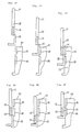
- Figs. 2A to 2F schematically show one embodiment of the present method;
- Figs. 3A to 3F schematically show another embodiment of the present invention; and
- Figs. 4A to 4D schematically show a further embodiment of the present invention.
-
In the drawings, the numerical number 1 represents a micropipette, 2 does a pipet body, 3 does a tip, 4 does an ejection button, 5 does a piston, 6 does a syringe, 7 does a stroke controlling piece, 8 does a spring, 9 does an O-ring, 10 does a pipet holder, 11 does a movable piece, 12 and 13 do light reflecting means, 14 does a light absorbing means, 15 and 16 do optical coupled sensors, 17 does a signal processing unit, 30 does a pipet holder, 31 does a movable piece, 33 does a portion of a micropipette body and 35 and 36 do mechanical sensors.
[PREFERRED MODE FOR CARRYING OUT THE INVENTION]
-
Generally, each step of the present detecting method comprises a step of detecting and confirming a relative positional relation between two elements.
-
That is, the step (1) comprises detecting and confirming the positional relation between the micropipette and the member on which the micropipette is disposed as preselected; the step (2) comprises detecting and confirming the positional relation between the ejection button (or the piston which correspondingly moves thereto) and the micropipette body; and the step (3) comprises detecting and confirming both of the positional relation between the micropipette body and the ejection button and the positional relation between the pipet holder and the micropipette.
-
In the present invention, such the positional relations are detected and confirmed by appropriate sensors. The useful sensor used in the present detecting method includes an optical coupled sensor, a mechanical sensor and a magnet sensor and combination thereof.
-
The term "optical coupled sensor" as used herein means an optical sensor in which a light emitting element and a light receiving element are combined together, and which has a function of emitting a given amount of light and also a function of detecting an amount of received light.
-
In the present invention, the optical coupled sensor is used in combination with a light reflecting means and a light absorbing means. The optical coupled sensor can detects either a state where the sensor detects light which is emitted from the optical coupled sensor and reflected by the light reflecting means, or a state where the sensor detects no reflected light. Thus, the positional relation where which means lies on the optical coupled sensor is detected on the basis whether the light emitted from the sensor is reflected or absorbed. Therefore, the optical coupled sensor and these means are disposed on portions the positional relations between which is required to be detected, whereby the positional relations can be grasped. For example, the positional relations between the pipet holder on which the optical coupled sensor is provided and each portion on which each means is provided can be grasped.
-
The term "mechanical sensor" as herein used means a sensor which detects the positional relation between a member and another member on which the sensor is provided by actuating a mechanical switch when the member and the sensor mechanically contact each other. That is, the presence or absence of the mechanical contact is detected in place of the receipt of the light or no light (or change in an amount of the received light).
-
The term "magnet sensor" as herein used means a sensor which detects the presence or absence, or the strength of magnetism such as a reed switch, a Hall element, a magneto-resistance element and so on.
-
The sensor which can be used in the present invention is not limited to the above sensors, and any other sensor can be used as long as it can detect the relative positional relation between the member on which the sensor is provided and other member. For example, an ultrasonic sensor may be used.
-
The position at which the sensor is provided is not limited, and any position is possible as long as the steps of the present invention can be confirmed. That is, the sensor is provided on the member of which positional relation is desired to be detected and confirmed or other member which moves correspondingly to the member of which positional relation is desired to be detected and confirmed (for example, an extension of such member).
-
In the step of disposing the micropipette at the preselected position, the sensor is provide at the suitable position of the micropipette and/or the member such as the pipet holder so that the sensor supplies a given signal when the micropipette is disposed as preselected. For example, when the mechanical sensor is used which is actuated by contact with a pin, the pin is provided at a suitable position of the pipet holder so that the micropipette contacts the pin when it is disposed as preselected.
-
To detect and confirm that the ejection button is pushed, the conventional method may be employed. For example, a magnet piece is so provided on the micropipette that it moves correspondingly to the ejection button, whereby the movement of the button is detected by the sensor provided on the pipette holder.
-
To detect and confirm that the micropipette leaves the spotted sample while the button remains in the pushed state, the relative positional relations among the ejection button of the micropipette, the micropipette body and the pipette holder. In this case, though a method which directly detects the positional relation of the three members may be used, two steps may be used in combination.
-
With respect to the number of the sensors, the more the number is, the more the detectable relations are, which is preferred in view of the detection and confirmation of the operating states of the micropipette and also accuracy thereof. However, economy and complication of the analyzing apparatus should be considered. Thus, the number of the sensors is selected depending on the requirements of the detection. In any case, the three detecting steps of the present invention should be carried out.
-
The detection and the confirmation of these three steps can be carried out with separate sensors. In this case, one step is ensured and then the next step is carried out, and the overall apparatus can be made simple. Alternatively, the detection and the confirmation of each step can be carried out continuously by designing a suitable sequence program of the three steps. Then, an analytical system can be made such that an analysis operation is stopped when abnormality is detected in one step, and is continued only when no abnormality is detected.
-
Thus, in the practice of the present invention, a suitable embodiment including a kind and the number of the sensor, the position at which the sensor is provided and so on should be selected depending on various requirements such as the accuracy of the analysis, the convenience, the economy and so on. As long as that the present detecting method is proposed, that is, a member to be detected is clear, those skilled in the art can easily select the suitable embodiment.
-
The way to carry out the present method will be described in detail with reference to the embodiment.
-
In one embodiment of the present invention, there is provided a method of detecting operating states of a micropipette comprising using two optical coupled sensors each of which comprises a light emitting element and a light receiving element, and a light reflecting means and a light absorbing means each disposed on a member which moves correspondingly to motion of a piston of the micropipette and a light reflecting means or a light absorbing means disposed on a micropipette body and detecting, on the basis of an amount of light which is emitted from the light emitting element, reflected by the light reflecting means and received by the light receiving element, states before a quantity of sample to be analyzed is ejected from the micropipette, on the ejection and after the ejection.
-
Further, the present invention provides a system to practice the present method comprising:
a pipette holder comprising two optical coupled sensors each having a light emitting element and a light receiving element;
a micropipette comprising a light reflecting means and a light absorbing means each disposed on a member which moves correspondingly to motion of a piston of the micropipette, and a light reflecting means or a light absorbing means disposed on a micropipette body; and
a signal processing unit which processes output signals supplied from the optical coupled sensors.
-
In this embodiment, the optical coupled sensor can output an amount of received light as the output signal, and it is preferably connected to the signal processing unit which decides whether the light emitted from the sensor is reflected depending on the output signal to grasp the state of the micropipette.
-
In addition, it is possible to decide whether a series of the steps are carried out as preselected on the basis of results of the signal processing, and also possible to feed the results back to a driving unit which actuates the micropipette and analytical units so as to exclude an analytical element incorrectly spotted. Alternatively, the output signals are recorded and then the analytical results from the incorrect spotting may be eliminated when the analytical data are evaluated later. As described above, the output signals can be processed and used in various manners depending on the object of the application.
-
In the optical coupled sensor, a light emitting diode, a semiconductive laser and so on can be used as the light emitting element, and a photo diode, a photo transistor, a photoconductive element (cds) and so on can be used as the light receiving element.
-
The commercially available optical coupled sensor includes a photointerrupter, a photoreflector, a photoelectric switch and so on, which are preferably used in the present invention.
-
As the light reflecting means, any means which reflects light can be used. Generally, a white piece or a mirror piece is used. As the light absorbing means, any means which absorbs light can be used. Generally, a black piece is used.
-
Depending on sensitivity of the optical coupled sensor, the light reflecting means does not necessarily reflect major amount of light, or the light absorbing means does not necessarily absorb major amount of light. That is, it is sufficient when the optical coupled sensor can detect the difference between an amount of light reflected from these means and the emitted light. Thus, it is sufficient if a relative reflectance (or absorbance) difference between these means can be detected by the sensor. Accordingly, the light reflecting means only has to reflect more light than the light absorbing means, and the light absorbing means only has to absorb more light than the light reflecting means.
-
In the preferred embodiment of the present invention, the optical coupled sensor is provided on the pipette holder and the light reflecting piece and the light absorbing piece are provided on the micropipette. The reversed disposing is possible, but the former disposing is most preferable in view of convenience of the disposition and removal of the micropipette and connection between the sensor and the signal processing unit.
-
When the number of the optical coupled sensor and the light absorbing means and the light reflecting means are increased, the number of the operating states of the micropipette which can be detected is increased. In the present detecting method, at least two optical coupled sensors, at least two light reflecting means and at least one light absorbing means are combined to detect the operating states of the pipette. With considering an apparatus cost and complication of the apparatus and also complication associated therewith, two optical coupled sensors and two light reflecting means and one light absorbing means are preferably combined, whereby the operating states of the micropipette can be confirmed with the signals supplied from the optical coupled sensors as described below.
-
Now, the present invention will be explained more in detail with reference to the above embodiment.
-
According to the present method, the light absorbing means and one light reflecting means are disposed on a portion which moves correspondingly to the motion of a piston of the micropipette along a direction of the movement of the piston so that the states of the micropipette body and the piston of the micropipette can be detected. For example, a member which moves correspondingly to the movement of the ejection button is provided, and the light absorbing means and one light reflecting means are provided on such member.
-
The other light reflecting means is provided on a portion which moves independently from the movement of the piston and correspondingly to the movement of the micropipette body.
-
The light absorbing means is so provided along a direction of the movement of the piston (and a direction along which the micropipette is disposed on the pipette holder, which direction is the same as that of the movement of the piston) that it is adjacently between the two light reflecting means. This means that one means and the remaining means are arranged in a straight line, and a light reflecting means are seemed to be on both sides of the light absorbing means when said one means is looked from a direction vertical to the direction of the piston movement.
-
The two optical coupled sensors are so disposed in a row that they lie on each means or they are away from the lying on state depending on the movement of the piston or the relative movement of the micropipette to the pipette holder.
-
In the embodiment as described above, when the light absorbing means is used in place of the light reflecting means and the light reflecting means in place of the light absorbing means, the output signals from the optical coupled sensors are only reversed, and above explanations are generally applied.
-
The present invention will be explained with reference to the accompanying drawings.
-
Fig. 1 shows a partially sectional view of a micropipette to which the present method is applied. The micropipette 1 is disposed on a suitable pipette holder 10. For example, the micropipette is exactly supported as preselected in an uneven shaped member corresponding to a shape of the micropipette.
-
The micropipette 1 comprises a micropipette body 2, a tip 3 and an ejection (pushing) button 4. A piston 5, a syringe 6, a stroke controlling piece 7 to control stroke length of the piston and a spring 8 to return the piston are provided in the micropipette body 2 as illustrated. The piston 5 and the syringe 6 are sealed in a suitable manner. In the illustrated embodiment, they are sealed by an O-ring 9.
-
In the embodiment shown in Fig. 1, for example a white piece 12 as the light reflecting means and a black piece 14 as the light absorbing means are adjacently disposed on a movable piece 11, which moves correspondingly to the ejection button 4, along a direction of the movement of the ejection button (hence along a direction of the movement of the piston). The other light reflecting means 13 is disposed on the pipette body 2.
-
As explained above, these three means are arranged in a straight line along the direction (arrow A) of the movement of the piston and the direction (arrow B) of the relative movement of the micropipette to the pipette holder (when looking from the right side of Fig. 1). When each portion itself on which each means is disposed reflects or absorbs light, the light reflecting means or the light absorbing means may not be required to be provided.
-
The optical coupled sensor 15 is disposed in a row on the micropipette body along the direction of the movement of the piston and the micropipette so that the sensors lie on the light absorbing means 14 or the light reflecting means 12 or 13 depending on the movement of the piston 5 and the micropipette body 2. Thus, when looking from the right side of Fig. 1, the optical sensors 15 and 16 are so arranged that they are in a straight row with the light absorbing means and the light reflecting means, or each sensor lies on one of these means.
-
When a quantity of the sample to be analyzed is spotted on an analytical element, there is, for example, a method comprising disposing the micropipette and the analytical element in a preselected state and then disposing the micropipette in a desired state, or a method comprising disposing the pipette holder and the analytical element in a preselected positional relation after disposing the micropipette on the pipette holder. Those skilled in the art will contemplate various embodiments of the present invention in which the optical coupled sensors are used.
-
The present invention will be explained with reference to the former embodiment as one example in which the optical sensors are used. As shown in an enlarged manner in Fig 2 which shows portions on which the optical coupled sensors 15 and 16, and the light absorbing means 14 and the light reflecting means 12 and 13 are provided, following six states can be detected by using the two light coupled sensors 15 and 16 when the micropipette and the pipette holder are arranged as in Fig. 1:
- (A) A state in which the micropipette is not disposed on the pipette holder 10;
- (B) A state in which the micropipette is being disposed on the pipette holder 10;
- (D) A state in which the micropipette is further being disposed on the pipette holder 10;
- (D) A state in which the disposition of the micropipette on the pipette holder 10 is completed and a portion 13 of the micropipette body is prevented from further going downwardly by the protrusion of the pipette holder;
- (E) A state in which the ejection of the sample is completed, that is, a state in which the ejection button remains in the pushed state and the sample is spotted on an analytical element, and the movable piece 11 which moves correspondingly to the ejection button is moved downwardly; and
- (F) A state in which the tip of the micropipette leaves the analytical element while the ejection button remains in the pushed state (that is, while the movable piece 11 and the pipette body 13 gets together).
-
Therefore, in the embodiment as shown in Fig. 2, the step (1) of the present detecting method corresponds to the detection and the confirmation of the states shown in Figs. 2A to 2D, the step (2) corresponds to the detection and the confirmation of the state shown in Fig. 2E and the step (3) corresponds to the detection and the confirmation of the state shown in Fig. 2F.
-
In Fig. 2, the light reflecting means 12 and 13 and the light absorbing means 14 are so shown that they also play roles to constitute portions of the micropipette.
-
The optical coupled sensors are connected to a signal processing unit, to which signals on the amount of the received light are supplied and processed therein.
-
For example, under assumption that "H" indicates the state in which the optical coupled sensor receives a given amount of light, and "L" indicates the state in which the sensor does not receive a given amount of light, the states as shown in Fig. 2 are explained as follows:
-
In Fig. 2A, the micropipette is above the pipette holder. The light emitted from the both optical coupled sensors is not reflected and it does not return to the sensors. Thus, the both sensors supplies the signal "L".
-
In Fig. 2B, since the light emitted from the sensor 15 is reflected by the light reflecting means 13, the sensor 15 receives the light and supplies the signal "H". Since the sensor 16 is in the same state as in Fig. 2A, it still supplies the signal "L".
-
In Fig. 2C, since the light emitted from the sensor 15 is absorbed by the light absorbing means 14, the sensor 15 supplies the signal "L". Since the sensor 16 is under the same state as that of the sensor 15 in Fig. 2B, the sensor now supplies the signal "H".
-
In Fig. 2D, since the light emitted from the sensor 15 is reflected by the light reflecting means 12, the sensor 15 supplies the signal "H". Since the sensor 16 is under the same state as that of sensor 15 in Fig. 2C, it supplies the signal "L".
-
In Fig. 2E, since the light emitted from each sensor is reflected by the light reflecting means 12, each sensor supplies the signal "H".
-
In Fig. 2F, since the light emitted from the sensor 15 is reflected by the light reflecting means 12, and the light from the sensor 16 is reflected by the light reflecting means 13, both sensors supply the signals "H".
-
The above explanations are summarized in following Table 1:
-
When the sensors 15 and 16 detect the above series of the signals, it is firstly confirmed that the preselected amount of the samples has been spotted. Thus, standard signals which are supplied when the micropipette is operated correctly as preselected are beforehand stored in the signal processing unit, and then the signals which are practically supplied are compared with the standard signals, whereby it is possible to determine whether the micropipette has been operated correctly as preselected.
-
Further, following system is possible: On the basis of the signal informations on the amount of the received light, the positional relations between the light absorbing piece and the light reflecting piece and the sensor are grasped, on which the states of the micropipette are judged and the next operation such as recording of the states or elimination of the analytical element on the incorrect spotting is carried out.
-
In another preferred embodiment of the present invention, mechanical sensors 35 and 36 are used in place of the optical coupled sensors as shown in Figs. 3A to 3F.
-
In Fig. 3, the micropipette is disposed on a pipette holder 30, and the mechanical sensors 35 and 36 are provided on the pipette holder 30. These sensors actuate by contact with a member 33 which is a portion of the micropipette body or a movable piece 11 which moves correspondingly to the ejection button. Thus, since the contact between the sensor and the member of which positional relation has to be detected and confirmed is required, the shape of the movable piece 31 is only changed to contact the sensors, whereby the similar results as in the embodiment of Fig. 2 using the optical coupled sensors can be obtained.
-
That is, under assumption that when the mechanical sensor 35 or 36 contacts a member, the sensor supplies a signal "ON", and when the sensor does not contact the member, it supplies a signal "OFF", there is an only difference that the state of Fig. 2 in which the signal "H" is supplied corresponds to the state of the signal "ON", and the state of Fig. 2 in which the signal "L" is supplied corresponds to the state of the signal "OFF".
-
When a magnet sensor is used, there is generally no difference from the case in which the mechanical sensors are used. That is, in the case of the magnet sensors, a signal corresponding to the signal "ON" is supplied even when the a certain gap may exist between the sensor and the member in place of the mechanical contact. Thus, when the magnet sensor is used, an embodiment may be employed in which the mechanical sensor lies on the member through a certain gap rather than the sensor contacts the member in the case using the mechanical sensor.
-
The mechanical sensor which can be used in the above embodiment includes, for example, a microswitch and a sensor using a movable piece. As the magnet sensor, a reed switch, a Hall element and a magneto-resistance element can be used.
-
A further embodiment of the present invention is shown in Fig. 4. In the embodiment shown in Fig. 4, one optical coupled sensor 15 is used. A light reflecting means 13 is disposed on a micropipette body, and a light absorbing means 14 is disposed on a movable piece 11.
-
Fig. 4A shows a state in which the micropipette is not disposed on a pipette holder 10, for example a state in which the pipette is waiting above the holder. In this state, the sensor has to supply a signal which is not "H" and also not "L". In such state, since the sensor receives some amount of light, that is, it receives a medium amount of light between "H" and "L", the sensor is, for example, so made that it can grasp the state in which the pipette is not disposed on the holder when the sensor receives such the medium amount of light. For example, the sensor is made to supply a signal "M" in such state.
-
Fig. 4B shows a state in which the micropipette is disposed on the pipette holder 10. In this case, the optical coupled sensor receives the light which it emits, and then it supplies the signal "H".
-
Fig. 4C shows a state in which the ejection button is pushed. In this case, the light emitted from the sensor is absorbed, and then the sensor supplies the signal "L".
-
Fig. 4D shows a state in which the micropipette leaves the pipette holder while the ejection button remains in the pushed state. If the button returns before the micropipette leaves the sample, the light absorbing means moves upwardly and the optical coupled sensor supplies the signal "H". Therefore, when the pipette leaves the sample while the ejection button remains in the pushed state, the signal from the optical coupled sensor supplies the signal "L", and then supplies the signal "M". These explanations are summarized in following Table 2.
-
Thus, the step (1) of the present detecting method corresponds to the step of detecting and confirming the states of Figs. 4A and 4B, the step (2) corresponds to the step of detecting and confirming the state of Fig. 4C, and the step (3) corresponds to the step of detecting and confirming the state of Fig. 4D.
-
When the series of the signals as shown in Table 2 is detected, the correct spotting with the micropipette is effected.
-
Though the number of the states which can be detected is reduced, there is no difference in that the three steps of the present detecting method is carried out. Then, the simplification is possible by the less sensors.
-
The present invention further provides an operating method of the micropipette in which the present detective method is used. A series of micropipette operations are carried out without an incorrect operation and exact spotting is possible by disposing the micropipette on the member, pushing the ejection button and separating the micropipette from the spotted sample while the ejection button remains in the pushed state so that the signals are supplied as preselected in the above detecting method.
-
In addition, the present invention provides a micropipette system in which operating states of the micropipette are detected and confirmed, which comprises the micropipette having sensors which act as described above and the member on which the micropipette is disposed, and optionally the signal processing unit which processes signals from the sensors.
[INDUSTRIAL APPLICABILITY]
-
In the method of detecting and confirming the operating states of the micropipette according to the present invention, a series of operating states can be detected and confirmed in which the micropipette is disposed on the pipette holder, the sample to be analyzed is spotted on the analytical element, and then the tip of the micropipette leaves the element.
-
In addition, by the operating method of the micropipette and the micropipette system in which uses the above operating state detecting method is used, the spotting by the micropipette can be effected exactly.