EP0427626A1 - Luftbehandlungsgerät mit Metallgerüst - Google Patents
Luftbehandlungsgerät mit Metallgerüst Download PDFInfo
- Publication number
- EP0427626A1 EP0427626A1 EP90403162A EP90403162A EP0427626A1 EP 0427626 A1 EP0427626 A1 EP 0427626A1 EP 90403162 A EP90403162 A EP 90403162A EP 90403162 A EP90403162 A EP 90403162A EP 0427626 A1 EP0427626 A1 EP 0427626A1
- Authority
- EP
- European Patent Office
- Prior art keywords
- panels
- wall
- frame
- insulating
- fixed
- Prior art date
- Legal status (The legal status is an assumption and is not a legal conclusion. Google has not performed a legal analysis and makes no representation as to the accuracy of the status listed.)
- Withdrawn
Links
- 229910052751 metal Inorganic materials 0.000 title claims abstract description 34
- 239000002184 metal Substances 0.000 title claims abstract description 34
- 229920003023 plastic Polymers 0.000 claims abstract description 16
- 239000004033 plastic Substances 0.000 claims abstract description 16
- 239000011810 insulating material Substances 0.000 claims abstract description 9
- 239000000463 material Substances 0.000 claims abstract description 4
- 238000007789 sealing Methods 0.000 claims description 7
- 230000002093 peripheral effect Effects 0.000 claims description 4
- 210000001835 viscera Anatomy 0.000 claims description 3
- 239000003570 air Substances 0.000 description 15
- 238000009833 condensation Methods 0.000 description 7
- 230000005494 condensation Effects 0.000 description 7
- 229910052782 aluminium Inorganic materials 0.000 description 5
- XAGFODPZIPBFFR-UHFFFAOYSA-N aluminium Chemical compound [Al] XAGFODPZIPBFFR-UHFFFAOYSA-N 0.000 description 5
- 239000012080 ambient air Substances 0.000 description 4
- 238000005553 drilling Methods 0.000 description 3
- 229920001084 poly(chloroprene) Polymers 0.000 description 3
- 229910001335 Galvanized steel Inorganic materials 0.000 description 2
- 229910000831 Steel Inorganic materials 0.000 description 2
- 239000000853 adhesive Substances 0.000 description 2
- 230000001070 adhesive effect Effects 0.000 description 2
- 239000011248 coating agent Substances 0.000 description 2
- 238000000576 coating method Methods 0.000 description 2
- 239000008397 galvanized steel Substances 0.000 description 2
- 239000010959 steel Substances 0.000 description 2
- 238000003466 welding Methods 0.000 description 2
- 229910001208 Crucible steel Inorganic materials 0.000 description 1
- 239000012790 adhesive layer Substances 0.000 description 1
- 238000004873 anchoring Methods 0.000 description 1
- 238000005452 bending Methods 0.000 description 1
- 230000015572 biosynthetic process Effects 0.000 description 1
- 238000004140 cleaning Methods 0.000 description 1
- 238000001816 cooling Methods 0.000 description 1
- 229920002457 flexible plastic Polymers 0.000 description 1
- 238000010438 heat treatment Methods 0.000 description 1
- 238000009434 installation Methods 0.000 description 1
- 238000009413 insulation Methods 0.000 description 1
- 238000004519 manufacturing process Methods 0.000 description 1
- 230000004048 modification Effects 0.000 description 1
- 238000012986 modification Methods 0.000 description 1
- 230000002787 reinforcement Effects 0.000 description 1
- 230000000284 resting effect Effects 0.000 description 1
Images


Classifications
-
- F—MECHANICAL ENGINEERING; LIGHTING; HEATING; WEAPONS; BLASTING
- F24—HEATING; RANGES; VENTILATING
- F24F—AIR-CONDITIONING; AIR-HUMIDIFICATION; VENTILATION; USE OF AIR CURRENTS FOR SCREENING
- F24F3/00—Air-conditioning systems in which conditioned primary air is supplied from one or more central stations to distributing units in the rooms or spaces where it may receive secondary treatment; Apparatus specially designed for such systems
- F24F3/044—Systems in which all treatment is given in the central station, i.e. all-air systems
- F24F3/0442—Systems in which all treatment is given in the central station, i.e. all-air systems with volume control at a constant temperature
-
- E—FIXED CONSTRUCTIONS
- E04—BUILDING
- E04H—BUILDINGS OR LIKE STRUCTURES FOR PARTICULAR PURPOSES; SWIMMING OR SPLASH BATHS OR POOLS; MASTS; FENCING; TENTS OR CANOPIES, IN GENERAL
- E04H1/00—Buildings or groups of buildings for dwelling or office purposes; General layout, e.g. modular co-ordination or staggered storeys
- E04H1/12—Small buildings or other erections for limited occupation, erected in the open air or arranged in buildings, e.g. kiosks, waiting shelters for bus stops or for filling stations, roofs for railway platforms, watchmen's huts or dressing cubicles
- E04H1/1205—Small buildings erected in the open air
- E04H1/1238—Shelters for engines, e.g. electrical meter housings
-
- F—MECHANICAL ENGINEERING; LIGHTING; HEATING; WEAPONS; BLASTING
- F24—HEATING; RANGES; VENTILATING
- F24F—AIR-CONDITIONING; AIR-HUMIDIFICATION; VENTILATION; USE OF AIR CURRENTS FOR SCREENING
- F24F13/00—Details common to, or for air-conditioning, air-humidification, ventilation or use of air currents for screening
- F24F13/20—Casings or covers
-
- F—MECHANICAL ENGINEERING; LIGHTING; HEATING; WEAPONS; BLASTING
- F24—HEATING; RANGES; VENTILATING
- F24F—AIR-CONDITIONING; AIR-HUMIDIFICATION; VENTILATION; USE OF AIR CURRENTS FOR SCREENING
- F24F13/00—Details common to, or for air-conditioning, air-humidification, ventilation or use of air currents for screening
- F24F13/22—Means for preventing condensation or evacuating condensate
- F24F2013/221—Means for preventing condensation or evacuating condensate to avoid the formation of condensate, e.g. dew
-
- F—MECHANICAL ENGINEERING; LIGHTING; HEATING; WEAPONS; BLASTING
- F24—HEATING; RANGES; VENTILATING
- F24F—AIR-CONDITIONING; AIR-HUMIDIFICATION; VENTILATION; USE OF AIR CURRENTS FOR SCREENING
- F24F2221/00—Details or features not otherwise provided for
- F24F2221/36—Modules, e.g. for an easy mounting or transport
Definitions
- the present invention relates to an air treatment apparatus and in particular to the structure of the frame of such an apparatus consisting of a rigid metal frame and a plurality of panels defining the faces of the apparatus.
- the air can undergo any cooling or heating action. It can also be a device in which air circulates at different temperature and hygrometry conditions from the air surrounding the device.
- Apparatuses of this type may comprise an envelope using a rigid framework materializing the edges of the volume occupied by the apparatus and panels defining the faces of said volume and fixed to the framework.
- a rigid framework material izing the edges of the volume occupied by the apparatus and panels defining the faces of said volume and fixed to the framework.
- Such a framework can be produced either in steel profiles obtained by bending or continuous forming, or in extruded aluminum profiles.
- thermal bridges When making an apparatus of this type, a number of difficulties are encountered, in particular relating to obtaining good airtightness and eliminating thermal bridges. It should also be able to easily fix the internal components of the device and offer vis-à-vis the outside, a suitable aesthetic. It will be noted that the presence of such thermal bridges generally results in condensations of the humidity contained in the ambient air on the cold outside parts of the device. It is therefore advisable to avoid the metallic conductive parts of the heat being exposed simultaneously to the air circulating inside the device and to the outside air or ambient air.
- the subject of the present invention is the production of such an air treatment apparatus, in which the structure of the frame makes it possible to obtain an excellent airtightness as well as a lack of metallic continuity between the interior environment and the external environment, in order to overcome thermal leaks and bridges and condensations outside the envelope.
- the invention also relates to a frame for such an apparatus which allows easy hooking of the internal components, in particular without requiring drilling of the framework.
- the invention also aims to allow the fixing of the side panels by external screws accessible to the user without risk of external condensation.
- the air treatment device comprises a frame constituted by a rigid metal frame materializing in particular the edges of the volume occupied by the device and panels defining the faces of said volume and fixed to this frame.
- the panels include an outer thin wall and an inner thin wall enclosing a core of insulating material.
- An insulating joint is placed between the rigid metal framework and at least the outer wall of the panels.
- the panels are fixed to the frame by screws passing through an edge of the outer wall of the panels as well as the insulating joint. In this way, the fixing of the panels is done without causing the formation of any thermal bridge, the insulating plastic seal being interposed between the outer wall of the panel and the frame which is subjected, for its part, to the conditions of internal temperatures of the appliance.
- the insulating joint can be fixed by clamping on the periphery of the outer and inner walls of the panels and optionally have at least one flexible lip capable of coming into contact with one face of the framework.
- the insulating joint can also, as a variant, be simply partially clamped between two peripheral edges of the respective walls of the panels.
- the interior wall of the panels has a peripheral rim directly fixed by screws to the metal framework.
- the portions of the framework which are not covered by the external wall of the panels are also covered by additional elements coming into contact with the framework via an insulating material. In this way, no portion of the metal framework facing the outside ambient air is exposed to the temperature of the ambient air. This avoids any risk of condensation of the moisture contained in the air outside the device, despite the direct exposure of the internal faces of the metal frame to the air at the inside the appliance.
- the framework is formed by metal sections of steel or aluminum.
- the profiles may have an angular section and have a protrusion forming a housing, allowing the fixing of an outer cover itself made of insulating plastic.
- Rods capable of concealing the screws for fixing the panels, can be mounted between the outer plastic cover mentioned above and the outer wall of a panel. All of these provisions provide coverage complete the framework towards the outside, thus avoiding, as has been indicated, any external condensation.
- the rods can advantageously be fixed by clamping in a suitable groove made in the outer cover.
- the rods preferably flexible, may also have a sealing lip which bears against the external wall of the panel.
- an additional seal is mounted between the inner wall of the panel and one face of the frame.
- a metal outer cover is fixed by screws in the corner of the profiles, insulating joints being arranged between the cover and the metal frame.
- the metal cover preferably has at least one lateral border capable of concealing the screws for fixing the panels and coming into contact with the external wall of the panels.
- the profiles can advantageously have an extension which can serve as a bearing face for the device.
- the profiles preferably have, on their internal face, anchoring slides for fixing internal organs of the device.
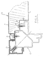
- the frame of the air treatment apparatus of the invention comprises a metal frame 1 in the form of a profile produced in the example illustrated in spun aluminum .
- the frame 1 which defines the edges of the volume occupied by the device, allows the fixing of insulating panels 2, an external plastic cover 3 and an insulating strip 4.
- the framework of the device comprises a plurality of straight sections 1, assembled by molded aluminum corner pieces, not shown in the figures. It is also possible to use such parts made of cast steel or by mechanical welding, of thick folded or stamped sheet metal, these parts being able to link, for example, three orthogonal sections of the framework. It will be understood that, in another embodiment, it is also possible to link the profiles together by direct welding.
- the panels 2 comprise an outer thin wall 5 which is constituted, for example, by a pressed sheet of galvanized steel, having on its periphery a flange 6.
- the panels 2 also comprise an inner thin wall 7 which can also be constituted by a galvanized steel sheet.
- the two walls 5 and 7 enclose a core 8 of insulating material.
- An insulating seal 9, made for example of plastic, allows the airtight mounting of the panel 2 on the profile 1 of the frame.
- the seal 9 formed in the form of a plastic profile comprises a flexible lip 10 molded, capable of coming into contact with a face 11 of the profile 1.
- the sealing lip 10 is placed as close as possible to the inner face of the device which is defined by the interior wall 7 of the panel 2, in order to limit as much as possible the spaces which have to be decontaminated during cleaning of the interior part of the device.
- the insulating joint 9 has a first groove 12 inside which the edge of the interior wall 7 can penetrate and a second groove 13 inside which the edge 6 of the exterior wall 5 of the panel 2 penetrates.
- panel 2 is fixed by a plurality of screws 14 which pass through holes made in the joint 9 at the location of the groove 13, in the flange 6 and in the wall of the profile 1.
- the screws 14 used can also be of the self-drilling screw type thus authorizing, in a simple manner, the installation of a large number of such screws, making it possible to ensure a regular reach of the panel 2 against the profile 1.
- tightening the screws 14 it is understood that the metal sheet of the outer wall 5 is clamped against the profile 1 with the interposition of the seal 9, thus limiting thermal leakage as far as possible at the location of the fastening of the panels 2.
- the assembly is completed by the outer cover 3 and the sealing strip 4.
- the outer cover 3 also made of plastic, is fixed by clipping a longitudinal rib 15 inside a housing 16 formed in a protrusion 17 at the corner of the profile 1, the housing 16 possibly having grooves which improve the fixing of the outer cover 3.
- the outer cover 3 has two grooves 18 allowing the mounting of the sealing strips 4.
- the strips 4 preferably made of flexible plastic material, have a side 19 which can be introduced into the groove 18 and come to bear elastically on their opposite side 20 against the outer wall 5 of the panel 2 in its front portion 21.
- the entire outer surface of the profile 1 is thus covered by an insulating material or by an element which is fixed to the profile by means of an insulating material. No condensation can therefore occur on contact with the outside air.
- the inner part of the profile 1 subject to the internal temperature conditions of the device further has two T-shaped grooves referenced 22 and 23 which constitute anchor slides for fixing internal organs of the device.
- the two orthogonal flat faces 4 and 25 arranged at the end of the protrusion 17, comprising the housing 16, can serve as bearing faces for the external plastic cover 3 on the profile 1 and thus support the weight of the device On the ground.
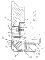
- the insulating seal 31 made for example of neoprene rubber provided with an adhesive layer, is in the form of a strip interposed partly between the edge 6 of the outer wall 5 of the panel 2 and the corresponding wall of the metal frame 1, being crossed by the fixing screws 14.
- Another part of the insulating joint 31 is, for its part, clamped between the edge 6 of the outer wall 5 and an edge 32 of the inner wall 7 of the panel 2, the edge 32 not being, unlike what is the case of the edge 6, crossed by the fixing screws 14.
- the insulating joint 31 has the same structure as in the embodiment of FIG. 2. It consists of a strip of neoprene rubber bonded by an adhesive coating on the opposite face of the metal framework 1.
- the inner wall 7 is fixed directly to the metal frame 1 by screws 33 which pass through the edge 32.
- Figures 5 and 6 illustrate a modification of the respective embodiments of Figures 3 and 4, in which the external cover 3 and the insulating strip 4 have been replaced by a metal cover 34 produced in the form of two joined profiles 34a, 34b made for example of aluminum.
- the metal cover 34 is mounted like the external cover 3 at the corner of the metal frame 1, by resting on the protrusion 17. The assembly is however done without using this time the housing 16 which remains on the metal frame 1 for the case where it would be preferable to mount a plastic cover as before 3.
- An insulating seal 35 made for example of neoprene rubber provided with an adhesive coating, covers the protrusion 17 and is clamped between it ci and the angle of the metal cover 34.
- Each metal section 34a, 34b has a rib 36 arranged perpendicular to the plane of the insulating panel 2 and capable of coming into contact with the lateral edge of the insulating joint 31. The fixing of the sections 34a, 34b is done by clamping screws 37 which penetrate into the metal frame walls 1.
- Each profile 34a, 34b further has a side edge 38 provided with a flange 39, which comes into contact with the outer wall 5 of the panel 2 and also makes it possible to conceal the fixing screws 14 replacing in this respect the insulating strips 4 embodiments illustrated in FIGS. 1 to 4.
- the structure of the frame of the air handling device of the invention makes it possible to obtain an excellent airtightness and an absence of metallic continuity between the interior and the exterior environment.
- the panels are easily fixed by external screws which are easily accessible to the user by simple deformation of the flexible material which constitutes the sealing strips 4 or possibly by dismantling the latter or the metal corner cover.
- the existence of these rods or of the insulating joints 31 and 35 makes it possible to avoid any risk of external condensation in combination with the particular mounting of the panels and the external covers 3 or 34.
- the structure of the profile 1 allows easy attachment of the internal components without drilling the frame, for example by means of captive nuts in the anchor slides 22 and 23.
Landscapes
- Engineering & Computer Science (AREA)
- Architecture (AREA)
- Chemical & Material Sciences (AREA)
- Combustion & Propulsion (AREA)
- Mechanical Engineering (AREA)
- General Engineering & Computer Science (AREA)
- Civil Engineering (AREA)
- Structural Engineering (AREA)
- Building Environments (AREA)
Applications Claiming Priority (2)
| Application Number | Priority Date | Filing Date | Title |
|---|---|---|---|
| FR8914589A FR2654199B1 (fr) | 1989-11-07 | 1989-11-07 | Appareil de traitement d'air a ossature metallique. |
| FR8914589 | 1989-11-07 |
Publications (1)
| Publication Number | Publication Date |
|---|---|
| EP0427626A1 true EP0427626A1 (de) | 1991-05-15 |
Family
ID=9387160
Family Applications (1)
| Application Number | Title | Priority Date | Filing Date |
|---|---|---|---|
| EP90403162A Withdrawn EP0427626A1 (de) | 1989-11-07 | 1990-11-07 | Luftbehandlungsgerät mit Metallgerüst |
Country Status (2)
| Country | Link |
|---|---|
| EP (1) | EP0427626A1 (de) |
| FR (1) | FR2654199B1 (de) |
Cited By (18)
| Publication number | Priority date | Publication date | Assignee | Title |
|---|---|---|---|---|
| WO1995033961A1 (de) * | 1994-06-09 | 1995-12-14 | Stulz Gmbh | Gerätegehäuse für klimageräte |
| AT404404B (de) * | 1997-02-07 | 1998-11-25 | Akra Ag | Kasten für klimageräte |
| GR1003076B (el) * | 1997-12-30 | 1999-02-12 | Αεροστεγης σκελετος κεντρικων μοναδων κλιματισμου με θερμοφραγμο | |
| NL1006974C2 (nl) * | 1997-09-08 | 1999-03-09 | Holland Heating Bv | Samenstel voor een luchtbehandelingskast, en luchtbehandelingskast omvattende dit samenstel. |
| WO2001079764A1 (en) * | 2000-04-14 | 2001-10-25 | Teba Isitma Sogutma Klima Teknolojileri A.S. | Casing for cold bridge-free air handling unit |
| EP1152194A1 (de) * | 2000-04-03 | 2001-11-07 | Seven-Air Gebr. Meyer AG | Eckverbindung eines Gehäuserahmens von Lüftungs- und Klimageräten |
| WO2002055941A1 (en) * | 2001-01-11 | 2002-07-18 | Teba Isitma Sogutma Klima Teknolojileri A.S. | Pentapost air handling unit casing |
| WO2001050067A3 (en) * | 1999-12-30 | 2002-10-10 | Carrier Corp | Air handler framework |
| KR100461742B1 (ko) * | 2000-09-05 | 2004-12-14 | 주식회사 신성이엔지 | 공조기의 케이스용 결로방지장치 |
| EP1538274A1 (de) * | 2003-12-03 | 2005-06-08 | Carrier Corporation | Platte für Luftbehandlungseinheit |
| ES2282000A1 (es) * | 2005-02-08 | 2007-10-01 | Schako Metallwarenfabrik Ferdinand Schad Kg | Procedimiento constructivo de un recinto envolvente de un aparato climatizador y recinto envolvente asi obtenido. |
| KR100951454B1 (ko) | 2009-09-15 | 2010-04-07 | 주식회사 삼화에이스 | 결로방지용 공기조화기 케이스 |
| DE102008063482A1 (de) * | 2008-12-17 | 2010-09-16 | Robatherm Gmbh + Co. Kg | Gehäuse für Lüftungs- und Klimageräte |
| CN102705968A (zh) * | 2011-02-10 | 2012-10-03 | 特洛克斯有限责任公司 | 容纳空调和/或通风设备组件的长方体形尤其是立方体形的外壳 |
| DK178436B1 (en) * | 2014-10-02 | 2016-02-29 | Linknordic Aps | Fire Insulation Cabinet for Air Handling Units |
| EP3217113A1 (de) * | 2016-03-10 | 2017-09-13 | Wolf GmbH | Gehäuse, insbesondere für heizungs-, lüftungs- oder klimageräte |
| EP2791591B1 (de) * | 2011-12-15 | 2019-09-11 | AL-KO Therm GmbH | Lüftungsgerät mit gehäuse |
| JP2021103014A (ja) * | 2019-12-25 | 2021-07-15 | クボタ空調株式会社 | 空気調和機のフレーム |
Families Citing this family (1)
| Publication number | Priority date | Publication date | Assignee | Title |
|---|---|---|---|---|
| DE4343759A1 (de) * | 1993-12-21 | 1995-06-22 | Wimboeck Besitz Gmbh | Lüftungsanordnung |
Citations (3)
| Publication number | Priority date | Publication date | Assignee | Title |
|---|---|---|---|---|
| CH402353A (fr) * | 1963-01-29 | 1965-11-15 | Aubecq Auxi | Panneau composite |
| WO1981000443A1 (fr) * | 1979-08-02 | 1981-02-19 | Luwa Ag | Boitier, en particulier pour appareils de climatisation et de ventilation ainsi que pour des machines telles que des machines textiles |
| DE3609767A1 (de) * | 1986-03-22 | 1987-09-24 | Fichtel & Sachs Ag | Gehaeuse fuer eine waermepumpe |
-
1989
- 1989-11-07 FR FR8914589A patent/FR2654199B1/fr not_active Expired - Fee Related
-
1990
- 1990-11-07 EP EP90403162A patent/EP0427626A1/de not_active Withdrawn
Patent Citations (3)
| Publication number | Priority date | Publication date | Assignee | Title |
|---|---|---|---|---|
| CH402353A (fr) * | 1963-01-29 | 1965-11-15 | Aubecq Auxi | Panneau composite |
| WO1981000443A1 (fr) * | 1979-08-02 | 1981-02-19 | Luwa Ag | Boitier, en particulier pour appareils de climatisation et de ventilation ainsi que pour des machines telles que des machines textiles |
| DE3609767A1 (de) * | 1986-03-22 | 1987-09-24 | Fichtel & Sachs Ag | Gehaeuse fuer eine waermepumpe |
Cited By (27)
| Publication number | Priority date | Publication date | Assignee | Title |
|---|---|---|---|---|
| DE4420133A1 (de) * | 1994-06-09 | 1995-12-14 | Stulz Gmbh | Gerätegehäuse für Klimageräte |
| WO1995033961A1 (de) * | 1994-06-09 | 1995-12-14 | Stulz Gmbh | Gerätegehäuse für klimageräte |
| AT404404B (de) * | 1997-02-07 | 1998-11-25 | Akra Ag | Kasten für klimageräte |
| US6350000B1 (en) | 1997-09-08 | 2002-02-26 | Holland Heating B.V. | Assembly for an air conditioner cabinet |
| NL1006974C2 (nl) * | 1997-09-08 | 1999-03-09 | Holland Heating Bv | Samenstel voor een luchtbehandelingskast, en luchtbehandelingskast omvattende dit samenstel. |
| WO1999013273A1 (en) * | 1997-09-08 | 1999-03-18 | Holland Heating B.V. | Assembly for an air conditioning cabinet |
| AU752182B2 (en) * | 1997-09-08 | 2002-09-12 | Holland Heating B.V. | Assembly for an air conditioning cabinet |
| GR1003076B (el) * | 1997-12-30 | 1999-02-12 | Αεροστεγης σκελετος κεντρικων μοναδων κλιματισμου με θερμοφραγμο | |
| EP0933599A1 (de) * | 1997-12-30 | 1999-08-04 | Tryfon Bisimis | Luftdichtes Rahmenprofil mit wärmehemmender Beschichtung für Luftbehandlungseinheit |
| WO2001050067A3 (en) * | 1999-12-30 | 2002-10-10 | Carrier Corp | Air handler framework |
| EP1152194A1 (de) * | 2000-04-03 | 2001-11-07 | Seven-Air Gebr. Meyer AG | Eckverbindung eines Gehäuserahmens von Lüftungs- und Klimageräten |
| WO2001079764A1 (en) * | 2000-04-14 | 2001-10-25 | Teba Isitma Sogutma Klima Teknolojileri A.S. | Casing for cold bridge-free air handling unit |
| US6792722B2 (en) | 2000-04-14 | 2004-09-21 | Erkut Beser | Casing for cold bridge-free air handling unit |
| KR100461742B1 (ko) * | 2000-09-05 | 2004-12-14 | 주식회사 신성이엔지 | 공조기의 케이스용 결로방지장치 |
| WO2002055941A1 (en) * | 2001-01-11 | 2002-07-18 | Teba Isitma Sogutma Klima Teknolojileri A.S. | Pentapost air handling unit casing |
| EP1538274A1 (de) * | 2003-12-03 | 2005-06-08 | Carrier Corporation | Platte für Luftbehandlungseinheit |
| ES2282000A1 (es) * | 2005-02-08 | 2007-10-01 | Schako Metallwarenfabrik Ferdinand Schad Kg | Procedimiento constructivo de un recinto envolvente de un aparato climatizador y recinto envolvente asi obtenido. |
| ES2282000B1 (es) * | 2005-02-08 | 2008-08-16 | Schako Metallwarenfabrik Ferdinand Schad Kg | Procedimiento constructivo de un recinto envolvente de un aparato climatizador y recinto envolvente asi obtenido. |
| DE102008063482B4 (de) * | 2008-12-17 | 2011-06-22 | robatherm GmbH + Co. KG, 89331 | Gehäuse für Lüftungs- und Klimageräte |
| DE102008063482A1 (de) * | 2008-12-17 | 2010-09-16 | Robatherm Gmbh + Co. Kg | Gehäuse für Lüftungs- und Klimageräte |
| KR100951454B1 (ko) | 2009-09-15 | 2010-04-07 | 주식회사 삼화에이스 | 결로방지용 공기조화기 케이스 |
| CN102705968A (zh) * | 2011-02-10 | 2012-10-03 | 特洛克斯有限责任公司 | 容纳空调和/或通风设备组件的长方体形尤其是立方体形的外壳 |
| CN102705968B (zh) * | 2011-02-10 | 2016-02-03 | 特洛克斯有限责任公司 | 容纳空调和/或通风设备组件的长方体形尤其是立方体形的外壳 |
| EP2791591B1 (de) * | 2011-12-15 | 2019-09-11 | AL-KO Therm GmbH | Lüftungsgerät mit gehäuse |
| DK178436B1 (en) * | 2014-10-02 | 2016-02-29 | Linknordic Aps | Fire Insulation Cabinet for Air Handling Units |
| EP3217113A1 (de) * | 2016-03-10 | 2017-09-13 | Wolf GmbH | Gehäuse, insbesondere für heizungs-, lüftungs- oder klimageräte |
| JP2021103014A (ja) * | 2019-12-25 | 2021-07-15 | クボタ空調株式会社 | 空気調和機のフレーム |
Also Published As
| Publication number | Publication date |
|---|---|
| FR2654199A1 (fr) | 1991-05-10 |
| FR2654199B1 (fr) | 1992-02-21 |
Similar Documents
| Publication | Publication Date | Title |
|---|---|---|
| EP0427626A1 (de) | Luftbehandlungsgerät mit Metallgerüst | |
| FR2502668A1 (fr) | Construction perfectionnee de lucarne | |
| FR2544451A1 (fr) | Bride de liaison pour parois de conduit de climatisation | |
| FR2587742A1 (fr) | Dispositif pour l'assemblage de panneaux et parois realisees avec ce dispositif, notamment pour une cabine de douche | |
| EP2186985B1 (de) | Gebäudeverschlusselement mit einer thermisch getrennten Zarge, die mit einem L-förmigen Dichtungsprofil ausgestattet ist | |
| FR2608739A1 (fr) | Porte de four de cuisson avec fenetre de regard | |
| FR2897928A1 (fr) | Carter, notamment pour appareil de chauffage, ventilation ou climatisation | |
| EP2865933A1 (de) | Einbauverfahren einer Wärmeschutzdichtung | |
| FR2742186A1 (fr) | Joint pour porte a montage rapide | |
| FR2648178A1 (fr) | Fenetre thermo isolante | |
| EP0972103B1 (de) | Wasserreservoir für dampfbügeleisen und verfahren zur herstellung eines derartigen reservoirs | |
| FR2509361A1 (fr) | Cadre d'adaptation realise en profiles, pour vitrage | |
| FR2474677A1 (fr) | Tube de chauffage en matiere plastique flexible | |
| FR2492880A1 (fr) | Chassis de fenetre a trois vitres | |
| FR2908261A1 (fr) | "panneau chauffant etanche et unidirectionnel pour radiateur electrique et radiateur electrique incluant un tel panneau" | |
| FR3018539A1 (fr) | Encadrement de menuiserie, ensemble et construction equipes d'un tel encadrement | |
| EP0823530B1 (de) | Aussenwand mit hoher Wärmeisolierung | |
| FR2707928A1 (fr) | Volet pivotant pour appareil de chauffage ou de climatisation de véhicule. | |
| EP0483056B1 (de) | Rahmen für Verkleidungs- oder Fenster-Paneel | |
| FR2496159A1 (fr) | Fenetre coupe-feu | |
| FR2780334A1 (fr) | Panneau composite aerostabilise | |
| FR2732443A1 (fr) | Dispositif de raccordement de deux troncons de gaine, notamment pour conduite de chauffage ou de ventilation | |
| BE885641A (fr) | Fenetre coupe-feu | |
| FR2650612A1 (fr) | Dispositif de fixation pour panneaux de facade | |
| FR2664645A1 (fr) | Encadrement et profile destine a cet encadrement notamment pour vitres, hublots, cloisons. |
Legal Events
| Date | Code | Title | Description |
|---|---|---|---|
| PUAI | Public reference made under article 153(3) epc to a published international application that has entered the european phase |
Free format text: ORIGINAL CODE: 0009012 |
|
| AK | Designated contracting states |
Kind code of ref document: A1 Designated state(s): AT BE CH DE DK ES FR GB GR IT LI LU NL SE |
|
| 17P | Request for examination filed |
Effective date: 19910604 |
|
| 17Q | First examination report despatched |
Effective date: 19911010 |
|
| STAA | Information on the status of an ep patent application or granted ep patent |
Free format text: STATUS: THE APPLICATION IS DEEMED TO BE WITHDRAWN |
|
| 18D | Application deemed to be withdrawn |
Effective date: 19930126 |