EP0430297A2 - Method and system for testing specimen of automotive power transmission connected to engine and analyzing engine output characteristic via specimen tested using dynamometer - Google Patents
Method and system for testing specimen of automotive power transmission connected to engine and analyzing engine output characteristic via specimen tested using dynamometer Download PDFInfo
- Publication number
- EP0430297A2 EP0430297A2 EP19900123004 EP90123004A EP0430297A2 EP 0430297 A2 EP0430297 A2 EP 0430297A2 EP 19900123004 EP19900123004 EP 19900123004 EP 90123004 A EP90123004 A EP 90123004A EP 0430297 A2 EP0430297 A2 EP 0430297A2
- Authority
- EP
- European Patent Office
- Prior art keywords
- power transmission
- engine
- torque
- output
- driving unit
- Prior art date
- Legal status (The legal status is an assumption and is not a legal conclusion. Google has not performed a legal analysis and makes no representation as to the accuracy of the status listed.)
- Granted
Links
Images




Classifications
-
- G—PHYSICS
- G01—MEASURING; TESTING
- G01M—TESTING STATIC OR DYNAMIC BALANCE OF MACHINES OR STRUCTURES; TESTING OF STRUCTURES OR APPARATUS, NOT OTHERWISE PROVIDED FOR
- G01M13/00—Testing of machine parts
- G01M13/02—Gearings; Transmission mechanisms
-
- G—PHYSICS
- G01—MEASURING; TESTING
- G01M—TESTING STATIC OR DYNAMIC BALANCE OF MACHINES OR STRUCTURES; TESTING OF STRUCTURES OR APPARATUS, NOT OTHERWISE PROVIDED FOR
- G01M13/00—Testing of machine parts
- G01M13/02—Gearings; Transmission mechanisms
- G01M13/025—Test-benches with rotational drive means and loading means; Load or drive simulation
-
- G—PHYSICS
- G01—MEASURING; TESTING
- G01M—TESTING STATIC OR DYNAMIC BALANCE OF MACHINES OR STRUCTURES; TESTING OF STRUCTURES OR APPARATUS, NOT OTHERWISE PROVIDED FOR
- G01M15/00—Testing of engines
-
- F—MECHANICAL ENGINEERING; LIGHTING; HEATING; WEAPONS; BLASTING
- F16—ENGINEERING ELEMENTS AND UNITS; GENERAL MEASURES FOR PRODUCING AND MAINTAINING EFFECTIVE FUNCTIONING OF MACHINES OR INSTALLATIONS; THERMAL INSULATION IN GENERAL
- F16H—GEARING
- F16H59/00—Control inputs to control units of change-speed- or reversing-gearings for conveying rotary motion
- F16H59/74—Inputs being a function of engine parameters
- F16H2059/743—Inputs being a function of engine parameters using engine performance or power for control of gearing
-
- F—MECHANICAL ENGINEERING; LIGHTING; HEATING; WEAPONS; BLASTING
- F16—ENGINEERING ELEMENTS AND UNITS; GENERAL MEASURES FOR PRODUCING AND MAINTAINING EFFECTIVE FUNCTIONING OF MACHINES OR INSTALLATIONS; THERMAL INSULATION IN GENERAL
- F16H—GEARING
- F16H59/00—Control inputs to control units of change-speed- or reversing-gearings for conveying rotary motion
- F16H59/14—Inputs being a function of torque or torque demand
- F16H59/16—Dynamometric measurement of torque
Definitions
- the present invention relates to a method and system for testing a specimen such as an automatic power transmission of vehicle and analyzing an engine output characteristic (input torque of the power transmission) via the specimen to be tested using a dynamometer (low inertia driving unit).
- the present invention more particularly, relates to the method and system in which the engine outout characteristic is estimated using, e.g., a low inertia driving unit when testing since the engine output characteristic cannot actually be measured in a system in which the engine and specimen are connected together.
- Fig. 9 shows a previously proposed transient dynamometer (refer to a United States Patent Application Serial No. 427, 031 filed on October 25, 1989).
- the low inertia driving unit (TR-DY) 1 includes a low inertia DC motor and speed governor.
- the DC motor performs a torque control or speed control as a current control minor loop of a thyristor reonard method to obtain a low inertia output equal to or more than the engine.
- An axial output of the drive unit 1 provides a drive source for a specimen of power transmission (AT) 3 via an axial torque meter 2.
- the axial output of the specimen automatic transmission 3 serves as a driving force for an energy absorbing dynamometer 5 and flywheel 5A via a torque meter 4.
- the low inertia driving unit 1, specimen automatic transmission 3, and energy absorbing dynamometer 5 are respectively provided with self-contained control units 6, 7, and 8.
- the TR-DY control unit 6 carries out a torque or speed control of the low inertia driving unit 1 in response to a torque or speed command.
- a feedback control is carried out by comparing the torque command derived from an engine characteristic generator 9 with the detected torque T 1 of the torque meter 2.
- speed control feedback control is carried out by comparing the speed command with the detected speed N1 of the speed detector 10.
- the engine characteristic generator 9 constituted by a microcomputer has a data such that an actual engine output torque T versus speed N characteristic is set or measured for each opening angle ⁇ i of an engine throttle valve. Then, the engine characteristic generator 9 derives a torque to be output by the low inertia drive unit 1 from the input opening angle of the thorttle valve and from the speed deteced value N1 so as to provide the torque command output. It is noted that although the opening angle of the throttle valve ⁇ i can be used in place of an engine intake negative pressure, the opening angle of the throttle valve ⁇ i is herein used.
- the engine characteristic generator 9 carries out data collection through an analysis of the actual engine output characteristic.
- a testing arrangement in which the torque meter, energy absorbing dynamometer, and flywheel (both absorbing dynamometer and flywheel providing a pesudo load to the power transmission) are connected to the power transmission may be considered (refer to Fig. 1 (B)).
- torque output T1 torque output
- a manual transmission which matches the engine is not always prepared. Actually, it is often impossible to accurately measure the engine output characteristic.
- the output characteristic data for the engine itself derived from the engine manufacturer may be used, the data may be different from the actual output characteristic data with the automatic transmission and load connected.
- an engine output characteristic i.e., output torque (input shaft torque) which can achieve analyisis and evaluate characteristics of the specimen on the basis of tested data on output shaft torque of the power transmission and input/ output shaft revolutional speed of the power transmission to obtain a highly reliable result without directly measuring the engine torque output.
- the above-described object can be achieved by providing a method for testing a engine output characteristic of an engine connected with a vehicular power transmission, comprising the steps of: a) measuring an engine operating parameter; b) measuring at least first revolutional speed on an input or output shaft of a power transmission connected to the engine and a first output torque of the power transmission when the engine operating parameter indicates a predetermined value; c) measuring a second revolutional speed on the input or output shaft of the power transmission and second output torque of the power transmission when a low inertia driving unit having the same characteristic as the engine is connected and driven with the power transmission under the same operating parameter measured in the step a); d) measuring a first drive torque of the low inertia driving unit in the state of step c); e) measuring a third revolutional speed on the input or output shaft of the power transmission and a third output torque of the power transmission when a predetermined time has elasped after the step c) and the same low inertia driving unit is connected and driven in the same
- a system for testing an output characteristic of an engine connected with a vehicular power transmission comprising; a) first means for measuring an engine operating parameter; b) second means for measuring least first revolutional speed on an input or output shaft of a power transmission connected to the engine and a first output torque of the power transmission when the engine operating parameter indicates a predetermined value; c) third means for measuring a second revolutional speed on the input or output shaft of the power transmission and second output torque of the power transmission when a low inertia driving unit having the same characteristic as the engine is connected and driven with the power transmission under the same operating parameter measured in the step a); d) fourth means for measuring a first drive torque of the low inertia driving unit in the state of step c); e) fifth means for measuring a third revolutional speed on the input or output shaft of the power transmission and a third output torque of the power transmission when a predetermined time has elasped after the step c) and the same low inertia
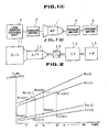
- Fig. 1 (A) is a schematic block diagram of a system used for testing a specimen such as a vehicular automatic transmission and analyzing an engine output characteristic in a first preferred embodiment according to the present invention.
- Fig. 1 (B) is a schematic block diagram of a testing arrangement used in a second preferred embodiment according to the present invention.
- Fig. 2 is an explanatory view for explaining a learning operation carried out for the system shown in Fig. 1.
- Fig. 3 is a characteristic graph representing examples of the engine output characteristics.
- Fig. 4 is a characteristic graph of an engine revolutional speed with respect to time.
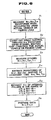
- Fig 5 is an operational flowchart explaining an operation executed by the system shown in Fig. 1.
- Fig. 6 is an operational flowchart explaining an analyzing procedure in the second preferred embodiment according to the present invention.
- Figs. 7 (A) through 7 (D) are waveform charts of accelerations in a case when an actual vehicle is tested in the second preferred embodiment.
- Figs. 8 (A) through 8 (D) are waveform charts of accelerations in a case when an ASR driving by means of a transient dynamometer in the second preferred embodiment is carried out.
- Fig. 9 is a schematic block diagram of a previously proposed transient dynamometer explained in the BACKGROUND OF THE INVENTION.
- Fig. 1 (A) shows a tesing system for a specimen such as a vehicular power transmission to analyze an engine output characteristic in a first preferred embodiment according to the present invention.
- a low inertia driving unit 3 is connected to an input portion of a specimen of power transmission (automatic transmission) l.
- An energy absorbing dynamometer 5 is connected to an output portion of the power transmission l via a torque meter 4.
- the low inertia driving unit 3 is a driving unit in which a DC motor is used to provide a low inertial force with an axial rigidity taken into a special consideration and to provide inertia equal to an engine. The structure of the low inertia driving unit 3 has been explained in the
- reference data T20(t) representing a change of an output shaft torque of the power transmission l with time for each opening angle of the engine throttle valve
- data N10(t) representing a change of the input shaft revolutional speed of the power transmission l with time for each opening angle of the engine throttle valve.
- Both reference data are derived from the system in which the engine is connected to the power transmission (refer to Fig. 1 (B)) or derived from a case wherein the engine is connected to the power transmission and installed in a vehicle and is actually driven on a road.
- a data T10(t) * 1 which would output the data T20 and N10 on the basis of a certain throttle valve opening angle ⁇ is calculated from a shift gear ratio and/or a predictive slip rate and supplied to the low inertia driving unit 3 as a torque command.
- the testing system shown in Fig. 1 (A) is prepared.
- *1 of the symbol T 10 (t)*1 denotes a first target value of the input shaft torque of the power transmission.
- T21(t) data representing a change of the output shaft torque of the power transmission with time
- N11(t) data representing a change of input shaft revolutional speed with time
- Fig. 2 shows a characteristic graph representing the reference data and first data. The subsequent procedure will be described with reference to Fig. 2.
- T21(t1') at the subsequent time t1' is derived, which outputs N11t1') of the same frequency as N10(t1) at the time t1.
- T21(t1') at the subsequent time t1' is derived to compare T20(t1) with T21(t1'). If T10(t) * 1 command input when deriving the first data coincides with the input shaft torque T10(t) of the specimen transmission, T20(t1) coincides with T21(t1'). If they do not coincide with each other, T21t1) is different from T21(t1'). That is to say, a difference between T20(t1) and T21(t1') at the time t1 provides an index for T10(t1) * 1 to be deviated from T10(t1).
- ⁇ T21(t1) is defined in the following equation (1):
- a second equation (2) is used to calculate a second command value T10(t1) * 2 from the value ⁇ T21(t1) and the first command value T20(t1) * 1:
- a denotes an adjustment coefficient for a value of ⁇ T21(t1) and gives a value in a range from 0 to 1, preferably 0. 5 to 0. 7.
- i denotes a gear ratio.
- the second command value T10(t k )*2 is supplied to the low inertia driving unit 3 as a torque command.
- a second data T22(t k ) and N12(t k ) are derived.
- t1 is representative.
- t1 ⁇ which outputs N12(t1') of the same frequency as N10(t1) in the same way as in the first data is derived.
- a third command value T10(t1) * 3 is calculated from the following equation (4) using ⁇ T22(t1)and the second command value T10(t1) * 2:
- the input shaft torque is estimated on the basis of the input shaft revolutional speed of the specimen transmission and output shaft torque. Driving is carried out with the estimated value as the command value. On the basis of the driving result, the input shaft torque is again estimated. In this way, a learning operation is carried out so as to derive an unknown input shaft torque.
- Reference data may be derived by increasing the revolutional speed or by decreasing the revolutional speed.
- the revolutional direction is the same way as that used to obtain the reference data.
- the data is excluded with the range specified for such region.
- Fig. 5 shows an operational flowchart executed until the data shown in Fig. 3 is derived by means of the learning operation.
- the reference data N10(t) and T20(t) are first set in a computer Then, the computer sets a correction coefficient a/i (refer to equations (2) and (4)) to convert the output shaft torque into the input shaft. Then, the predictive input shaft torque T10(t) * 1 is derived and input to the computer to carry out a first simulation driving. It is noted that T10(t) * 1 is time series data of predictive values at each of times t1 through t m . Next, the values of the input shaft revolutional speed and output shaft torque at respective times t1 to t m are sampled and recorded. Thereafter, a data erasion area is specified each time T2 n (t) is derived. Then, the computer determines whether all of
- the torque detected value of the torque meter 2 at each time is the input shaft torque when the reference data is derived.
- the reference engine characteristic data shown in Fig. 3 is prepared.
- indicate a value equal to b or more, the second torque command value T10(t) * 2 is calculated to perform the second simulation, and the same processing is carried out.
- specifying a data erasion area may include a method in which the erasion area varies over time for input shaft revolutional speed, output shaft revolutional speed, and output shaft torque, i.e., N1 l (t), N2 l (t), and T2 l (t) are displayed on a screen of a CRT (Cathode Ray Tube) (l denotes an integer) and a cursor is used to specify the data erasion area, a method in which a region of a speed ratio N2 . i/N1 ⁇ ⁇ K (K denotes a constant such as 0. 9) is automatically eliminated, and a method in which a space of time in which an external signal is input is automatically eliminated.
- Fig. 6 shows an operational flowchart of analyzing procedure in a second preferred embodiment according to the present invention.
- a step S1 with the engine 11 and specimen transmission 12 connected to the energy absorbing dynamometer 14 as the pesudo load and flywheel 15 as shown in Fig. 1 (B), waveforms of the engine revolutional speed N1, output shaft revolutional speed N2 of the autoamtic transmission 12 and output shaft torque T2 when the opening angle of the throttle valve of the engine 11 is accelerated from ⁇ 0 to a testing opening angle ⁇ 1 are measured.
- the waveform example at this time is observed for the gear ranges of the automatic transmission (e.g. 1st through 3rd) as shown in Figs. 7 (A) through 7 (D).
- the output shaft torque T2 also provides a particular behavior accompanied with a torque shock during shift change.
- T1 denotes a torque predicted waveform of the engine output shaft.
- the waveform charts N10, N20, and T20 of data N1, N2, and T2 caused by the pseudo load in the step S1 may be derived front the actual measurement values of the vehicle.
- the TR-DY control unit 6 carries out the speed control for the low inertia driving unit 1 with the waveform data N10 in the step S1 being the speed command N11.
- the output torque T11 of the low inertia driving unit 1 with the waveform data N10 in the step S1 is the speed command N11.
- the output torque T11 of the low inertia driving unit 1 is measured with respect to the change in the speed N11, output torque T21 of the specimen transmission 3, and revolutional speed N21 .
- the waveform charts measured at this time are shown with N10, N20, T20 and T10, measured in the step S1 overlapped, in Figs. 8 (A) through 8 (D).
- the measured waveforms in the step S3 are measured substantially in an analogous form in which a time axis is shifted by a control response delay of the transient dynamometer as compared with the waveform chart of the pseudo load, in the construction shown in Fig. 1 (B).
- a step S4 the waveform data N10', N20', and T20' which are deviated from the waveform charts N10, N20, and T20 measured in the step S4 by constant times (normally, 0.1 seconds to 0.5 seconds) are derived so that, in a step S5, respective deviations are derived between the measured data N11, N21, T21 in the step S3.
- an output torque T11 during an interval within an allowance value previously set is extracted.
- the extracted torque T11 is derived at the throttle valve opening angle ⁇ 1 from the engine revolutional speed N11 and throttle opening angle ⁇ 1. This is used as engine characteristic generator 9 data in a step S6. It is noted that the torque data T11 at an interval in which the data does not fall within the allowed deviations N1, N2, and T2 is determined by means of a straight line interpolation between the torque data T11 which falls in the allowance deviation.
- the processings in the steps S1 through S6 are caused by the analysis of the output torque t11 at the throttle opening angle ⁇ 1. Substqantially the same processings are carried out for the other opening angles ⁇ 0 through 0 n .
- the engine characteristics are determined for the respective speeds for the opening angles of the throttle valves ⁇ 0 through ⁇ n .
- the testing conditions and engine revolutional speed are obtained substantially the same as the actual vehicle under operating conditions. These are derived by carrying out the speed control through the dynamometer which meets the testing condition for the data N10, N20, and T20 on the testing condition in which the engine is connected to the automatic transmission in an actual vehicle or under a pseudo load.
- the same engine characteristics as the behavior of the actual vehicle are derived by limiting the data N11, N21, and T21 and each deviated value to fall within a certain range within the allowance value.
- the same engine characteristics as the behavior of the actual vehicle can be derived by estimating and extracting the torque T11 in the interval as the output torque of the engine.
- step S1 measurement in the step S1 is integrally measured for the opening angles ⁇ 0 through ⁇ n to store the data at each throttle valve opening angle. Then, measurements using the transient dynamometer in the steps S2 through S6 and data processing are integrally made for respective throttle valve opening angles. Consequently, operation is simplified.
- this method can be applied to analysis of output characteristics of another dynamometer in a case where the engine characteristic generator data in the chassis dynamometer is derived.
- the learning operation is carried out in the system in which the low inertia driving unit is used on the basis of the input shaft revolutional speed or output shaft revolutional speed of the power transmission and output shaft torque of the power transmission in the system in which the engine is connected to the power transmission so that the unkown input shaft torque of the power transmission is estimated.
- the input shaft torque or the power transmission in the system using the engine can accurately be recognized.
- testing equal to the system in which the engine is used can be executed grasping the input shaft torque of the power transmission.
- the characteristic analysis and evaluation of the specimen power transmission can be carried out with high reliability.
- troubleshooting of the power transmission can accurately be carried out.
- the waveform measurement of the behavior of the power transmission connected to the vehicular engine used in the system using the actual vehicle or under pseudo load are carried out, waveform measurement of the behaviors of the DC motor and power transmission when a dynamometer having the same testing condition is used to match the speed change with that in the case of the engine connection are carried out, and the output torque of the DC motor in an interval in which both measured waveforms become analogous to each other is estimated as the engine output torque.
- Analysis of engine output characteristic and engine output characteristic data which accords with the actual behavior of a power transmission and engine actually mounted in a vehicle can be executed.
Landscapes
- Physics & Mathematics (AREA)
- General Physics & Mathematics (AREA)
- Testing Of Engines (AREA)
- Testing Of Devices, Machine Parts, Or Other Structures Thereof (AREA)
Abstract
Description
- The present invention relates to a method and system for testing a specimen such as an automatic power transmission of vehicle and analyzing an engine output characteristic (input torque of the power transmission) via the specimen to be tested using a dynamometer (low inertia driving unit). The present invention, more particularly, relates to the method and system in which the engine outout characteristic is estimated using, e.g., a low inertia driving unit when testing since the engine output characteristic cannot actually be measured in a system in which the engine and specimen are connected together.
- It is necessary to grasp engine output characteristicd in analyzing and evaluating characteristics of power transmissions to be installed in automotive vehicles and for general troubleshooting for automatic transmissions. Therefore, although testing is carried out with the automotive power transmission as a specimen connected to a vehicular engine, it is difficult in construction to insert a torque meter between the engine and power transmission. Consequently, an accurate measurement of torque of an input shaft of the power transmission cannot be made. To code with such a problem described above, the engine output characteristic data supplied from an engine manufacturer has been used when evaluating a performance of the power transmission.
- However, since it cannot be accurately determined whether the actual output of the engine connected to the power transmission coincides with the derived output characteristic data high reliability cannot rest on the obtained result.
- In addition, in transient performance testing of the power transmission, with a specimen power transmission connected to an engine, output control of the engine is carried out to test acceleration/deceleration endurance and gear shift 'feel' of the power transmission.
- In such an engine driving method as described above it is difficult to repeatedly reproduce the same engine operating conditions. Consequently, a motor driving method has been adopted. In a transient dynamometer used in the motor driving method, a low inertia driving unit having a low inertia equal to or more than that of the engine and the same output characteristic transient is used to realize a large change of speed during gear shift operation.
- Fig. 9 shows a previously proposed transient dynamometer (refer to a United States Patent Application Serial No. 427, 031 filed on October 25, 1989).
- The low inertia driving unit (TR-DY) 1 includes a low inertia DC motor and speed governor. The DC motor performs a torque control or speed control as a current control minor loop of a thyristor reonard method to obtain a low inertia output equal to or more than the engine. An axial output of the
drive unit 1 provides a drive source for a specimen of power transmission (AT) 3 via anaxial torque meter 2. The axial output of the specimenautomatic transmission 3 serves as a driving force for anenergy absorbing dynamometer 5 andflywheel 5A via atorque meter 4. The lowinertia driving unit 1, specimenautomatic transmission 3, andenergy absorbing dynamometer 5 are respectively provided with self-containedcontrol units 6, 7, and 8. - The TR-DY control unit 6 carries out a torque or speed control of the low
inertia driving unit 1 in response to a torque or speed command. In the torque control, a feedback control is carried out by comparing the torque command derived from an engine characteristic generator 9 with the detected torque T1 of thetorque meter 2. On the other hand, for speed control, feedback control is carried out by comparing the speed command with the detected speed N₁ of thespeed detector 10. - The engine characteristic generator 9 constituted by a microcomputer has a data such that an actual engine output torque T versus speed N characteristic is set or measured for each opening angle ϑi of an engine throttle valve. Then, the engine characteristic generator 9 derives a torque to be output by the low
inertia drive unit 1 from the input opening angle of the thorttle valve and from the speed deteced value N₁ so as to provide the torque command output. It is noted that although the opening angle of the throttle valve ϑi can be used in place of an engine intake negative pressure, the opening angle of the throttle valve ϑi is herein used. - In the previously proposed transient dynamometer, the engine characteristic generator 9 carries out data collection through an analysis of the actual engine output characteristic.
- In order to coincide with a behavior of an actual vehicle during the analysis of the engine output characteristic, a testing arrangement in which the torque meter, energy absorbing dynamometer, and flywheel (both absorbing dynamometer and flywheel providing a pesudo load to the power transmission) are connected to the power transmission may be considered (refer to Fig. 1 (B)). However, it is difficult to directly measure the output characteristic (torque output T₁) by means of the action of a torque converter of the automatic transmission. Therefore, although a method for measuring the engine output from the torque meter in a shifted state of a four-speed (gear shift ratio of 1 : 1) manual transmission with a manual transmission connected in place of an automatic transmission has been adopted. However a manual transmission which matches the engine is not always prepared. Actually, it is often impossible to accurately measure the engine output characteristic.
- As described above, although the output characteristic data for the engine itself derived from the engine manufacturer may be used, the data may be different from the actual output characteristic data with the automatic transmission and load connected.
- It is an object of the present invention to provide a reliable method and system for testing a specimen such automotive power transmission and analyzing an engine output characteristic, i.e., output torque (input shaft torque) which can achieve analyisis and evaluate characteristics of the specimen on the basis of tested data on output shaft torque of the power transmission and input/ output shaft revolutional speed of the power transmission to obtain a highly reliable result without directly measuring the engine torque output.
- The above-described object can be achieved by providing a method for testing a engine output characteristic of an engine connected with a vehicular power transmission, comprising the steps of: a) measuring an engine operating parameter; b) measuring at least first revolutional speed on an input or output shaft of a power transmission connected to the engine and a first output torque of the power transmission when the engine operating parameter indicates a predetermined value; c) measuring a second revolutional speed on the input or output shaft of the power transmission and second output torque of the power transmission when a low inertia driving unit having the same characteristic as the engine is connected and driven with the power transmission under the same operating parameter measured in the step a); d) measuring a first drive torque of the low inertia driving unit in the state of step c); e) measuring a third revolutional speed on the input or output shaft of the power transmission and a third output torque of the power transmission when a predetermined time has elasped after the step c) and the same low inertia driving unit is connected and driven in the same way as the step c); and f) measuring a second drive torque of the low inertia driving unit when difference in the values of the second and third revolutional speeds and second and third output torques fall within a predetermined range, the second drive torque being estimated as the output characteristic of the engine connected to the power transmission.
- The above-described object can also be achieved by providing a system for testing an output characteristic of an engine connected with a vehicular power transmission, comprising; a) first means for measuring an engine operating parameter; b) second means for measuring least first revolutional speed on an input or output shaft of a power transmission connected to the engine and a first output torque of the power transmission when the engine operating parameter indicates a predetermined value; c) third means for measuring a second revolutional speed on the input or output shaft of the power transmission and second output torque of the power transmission when a low inertia driving unit having the same characteristic as the engine is connected and driven with the power transmission under the same operating parameter measured in the step a); d) fourth means for measuring a first drive torque of the low inertia driving unit in the state of step c); e) fifth means for measuring a third revolutional speed on the input or output shaft of the power transmission and a third output torque of the power transmission when a predetermined time has elasped after the step c) and the same low inertia driving unit is connected and driven in the same way as the step c); and f) sixth means for measuring a second drive torque of the low inertia driving unit when difference in the values of the second and third revolutional speeds and second and third output torques fall within a predetermined range, the second drive torque being estimated as the output characteristic of the engine connected to the power transmission.
- Fig. 1 (A) is a schematic block diagram of a system used for testing a specimen such as a vehicular automatic transmission and analyzing an engine output characteristic in a first preferred embodiment according to the present invention.
- Fig. 1 (B) is a schematic block diagram of a testing arrangement used in a second preferred embodiment according to the present invention.
- Fig. 2 is an explanatory view for explaining a learning operation carried out for the system shown in Fig. 1.
- Fig. 3 is a characteristic graph representing examples of the engine output characteristics.
- Fig. 4 is a characteristic graph of an engine revolutional speed with respect to time.
- Fig 5 is an operational flowchart explaining an operation executed by the system shown in Fig. 1.
- Fig. 6 is an operational flowchart explaining an analyzing procedure in the second preferred embodiment according to the present invention.
- Figs. 7 (A) through 7 (D) are waveform charts of accelerations in a case when an actual vehicle is tested in the second preferred embodiment.
- Figs. 8 (A) through 8 (D) are waveform charts of accelerations in a case when an ASR driving by means of a transient dynamometer in the second preferred embodiment is carried out.
- Fig. 9 is a schematic block diagram of a previously proposed transient dynamometer explained in the BACKGROUND OF THE INVENTION.
- Reference will hereinafter be made to the drawings in order to facilitate a better understanding of the present invention.
- Fig. 1 (A) shows a tesing system for a specimen such as a vehicular power transmission to analyze an engine output characteristic in a first preferred embodiment according to the present invention.
- A low
inertia driving unit 3 is connected to an input portion of a specimen of power transmission (automatic transmission) l. Anenergy absorbing dynamometer 5 is connected to an output portion of the power transmission l via atorque meter 4. The lowinertia driving unit 3 is a driving unit in which a DC motor is used to provide a low inertial force with an axial rigidity taken into a special consideration and to provide inertia equal to an engine. The structure of the lowinertia driving unit 3 has been explained in the - A procedure in which the output characteristic of the engine is derived from a system in which the engine is connected to a specimen power transmission will be described below.
- First, two types of reference data are prepared, these reference data being data T₂₀(t) representing a change of an output shaft torque of the power transmission l with time for each opening angle of the engine throttle valve and data N₁₀(t) representing a change of the input shaft revolutional speed of the power transmission l with time for each opening angle of the engine throttle valve. Both reference data are derived from the system in which the engine is connected to the power transmission (refer to Fig. 1 (B)) or derived from a case wherein the engine is connected to the power transmission and installed in a vehicle and is actually driven on a road.
- Next, with the testing arrangement shown in Fig. 1 (A), a data T₁₀(t)*1 which would output the data T₂₀ and N₁₀ on the basis of a certain throttle valve opening angle ϑ is calculated from a shift gear ratio and/or a predictive slip rate and supplied to the low
inertia driving unit 3 as a torque command. Thus, the testing system shown in Fig. 1 (A) is prepared. - It is noted that *1 of the symbol T10(t)*1 denotes a first target value of the input shaft torque of the power transmission.
- Initially derived at the first time of testing is data representing a change of the output shaft torque of the power transmission with time is T₂₁(t), data representing a change of input shaft revolutional speed with time is N₁₁(t). Values of T₂₁(t) and N₁₁(t) at time tk (k denotes an integer) are represented by T21(tk) and N₁₁(tk).
- Fig. 2 shows a characteristic graph representing the reference data and first data. The subsequent procedure will be described with reference to Fig. 2.
- t₁' is derived, which outputs N₁₁t₁') of the same frequency as N₁₀(t₁) at the time t₁. Next, T₂₁(t₁') at the subsequent time t₁' is derived to compare T₂₀(t₁) with T₂₁(t₁'). If T₁₀(t)*1 command input when deriving the first data coincides with the input shaft torque T₁₀(t) of the specimen transmission, T₂₀(t₁) coincides with T₂₁(t₁'). If they do not coincide with each other, T₂₁t₁) is different from T₂₁(t₁'). That is to say, a difference between T₂₀(t₁) and T₂₁(t₁') at the time t₁ provides an index for T₁₀(t₁)*1 to be deviated from T₁₀(t₁).
- Then, ΔT₂₁(t₁) is defined in the following equation (1):

- A second equation (2) is used to calculate a second command value T₁₀(t₁)*2 from the value ΔT₂₁(t₁) and the first command value T₂₀(t₁)*1:

- In the equation (2), a denotes an adjustment coefficient for a value of △T₂₁(t₁) and gives a value in a range from 0 to 1, preferably 0. 5 to 0. 7. In addition, i denotes a gear ratio. In this way, a deviation △T₂₁(t₁) of the output shaft torque of the specimen transmission is converted to deviation of the input shaft torque. Similarly, the second command value T₁₀(t)*2 is derived for times t₂, t₃, --, tm.
- The second command value T₁₀(tk)*2 is supplied to the low
inertia driving unit 3 as a torque command. When the system shown in Fig. 1 is driven, a second data T₂₂(tk ) and N₁₂(tk) are derived. - Suppose that t₁ is representative. t₁ʼ which outputs N₁₂(t₁') of the same frequency as N₁₀(t₁) in the same way as in the first data is derived. A difference △T₂₂(t₁) between T₂₀(t₁) and T₂₂(t₁') at a time t₁' is derived using the following equation (3):

- A third command value T₁₀(t₁)*3 is calculated from the following equation (4) using △T₂₂(t₁)and the second command value T₁₀(t₁)*2:

- In this way, the driving is repeated to derive data n number of times. When, deriving this data, respective △T₂n(t₁), △T₂n(t₂), △T₂n(t₂), ---, △T₂n(tm) give substantially zeros, ,i.e., when |△T₂n(tk) | ≦αµρ¨ b at any time (b denotes a set value), torque detected values T₁n(t₁), T₁n(t₂), ---, T₁n(tm) of the
torque meter 2 at each time are estimated values of the input shaft torque of the specimen transmission during the driving in operation when using the reference data T₂₀(t) and N₂₀(t). - In the above described method, the input shaft torque is estimated on the basis of the input shaft revolutional speed of the specimen transmission and output shaft torque. Driving is carried out with the estimated value as the command value. On the basis of the driving result, the input shaft torque is again estimated. In this way, a learning operation is carried out so as to derive an unknown input shaft torque.
- In this way, the estimation of the input shaft torque is carried out for each opening angle of the throttle valve. When, with the opening angle ϑi as the parameter, a relationship between the input shaft torque T₁ and output shaft revolutional speed is derived, a graph shown in Fig. 3 is obtained.
- Hence, when the low
inertia driving unit 3 is driven on the basis of the graph shown in Fig. 3 and the system is driven shown in Fig. 1 (A), testing equal to the actual system of intended use can be carried out, obtaining acutal input shaft torque, to investigate driving characteristics of the specimen transmission. - As described above, the same or same type of specimen transmission from which the reference data is derived is used as the specimen transmission in the system shown in Fig. 1 (A). Load inertia is derived in the same way as the reference data described above.
- Reference data may be derived by increasing the revolutional speed or by decreasing the revolutional speed. When the learning operation is carried out, the revolutional direction is the same way as that used to obtain the reference data. In addition, since error easily occurs in a region such as a converter region or gear shift region in which a conversion efficiency is changed due to a torque converter action of the specimen transmission as shown in Fig. 4, the data is excluded with the range specified for such region.
- Fig. 5 shows an operational flowchart executed until the data shown in Fig. 3 is derived by means of the learning operation.
- In the flowchart shown in Fig. 5, the reference data N₁₀(t) and T₂₀(t) are first set in a computer Then, the computer sets a correction coefficient a/i (refer to equations (2) and (4)) to convert the output shaft torque into the input shaft. Then, the predictive input shaft torque T₁₀(t)*1 is derived and input to the computer to carry out a first simulation driving. It is noted that T₁₀(t)*1 is time series data of predictive values at each of times t₁ through tm. Next, the values of the input shaft revolutional speed and output shaft torque at respective times t₁ to tm are sampled and recorded. Thereafter, a data erasion area is specified each time T₂n(t) is derived. Then, the computer determines whether all of |△ T₂n(t) | are smaller than the set value b. If it is
- smaller, the torque detected value of the
torque meter 2 at each time is the input shaft torque when the reference data is derived. The reference engine characteristic data shown in Fig. 3 is prepared. In addition, if any one of the values of | T₂n(t) | indicate a value equal to b or more, the second torque command value T₁₀(t)*2 is calculated to perform the second simulation, and the same processing is carried out. - Although in the above described example the data is derived for each opening angle of the throttle valve, the data may be derived for each parameter value, for example, intake manifold pressure, etc. In addition; specifying a data erasion area may include a method in which the erasion area varies over time for input shaft revolutional speed, output shaft revolutional speed, and output shaft torque, i.e., N₁ℓ(t), N₂ℓ(t), and T₂ℓ(t) are displayed on a screen of a CRT (Cathode Ray Tube) (ℓ denotes an integer) and a cursor is used to specify the data erasion area, a method in which a region of a speed ratio N₂.i/N₁≦αµρ¨ K (K denotes a constant such as 0. 9) is automatically eliminated, and a method in which a space of time in which an external signal is input is automatically eliminated.
- Fig. 6 shows an operational flowchart of analyzing procedure in a second preferred embodiment according to the present invention.
- In a step S₁, with the
engine 11 andspecimen transmission 12 connected to theenergy absorbing dynamometer 14 as the pesudo load and flywheel 15 as shown in Fig. 1 (B), waveforms of the engine revolutional speed N₁, output shaft revolutional speed N₂ of theautoamtic transmission 12 and output shaft torque T₂ when the opening angle of the throttle valve of theengine 11 is accelerated from ϑ₀ to a testing opening angle ϑ₁ are measured. The waveform example at this time is observed for the gear ranges of the automatic transmission (e.g. 1st through 3rd) as shown in Figs. 7 (A) through 7 (D). The output shaft torque T₂ also provides a particular behavior accompanied with a torque shock during shift change. In Figs. 7 (A) through 7 (D), T₁ denotes a torque predicted waveform of the engine output shaft. - It is noted that the structure shown in Fig. 1 (B) and Fig. 9 is exemplified by United States Patent Application Serial No. 427, 031 filed on October 25, 1989 (which corresponds to European Patent Application No. 89311002.3 filed on october 25, 1989 and published as No. 0366446), the disclosure of which is herein incorporated by reference.
- The waveform charts N₁₀, N₂₀, and T₂₀ of data N₁, N₂, and T₂ caused by the pseudo load in the step S₁ may be derived front the actual measurement values of the vehicle.
- Next, in the construction of the dynamometer of Fig. 9, the testing conditions of both
energy absorbing dynamometer 5 andflywheel 5A are met with the actual vehicle or peseudo load, the same as those in measuring step of step S₁. Thespecimen 3 is the same or same type ofautomatic transmission 12. The TR-DY control unit 6 carries out the speed control for the lowinertia driving unit 1 with the waveform data N₁₀ in the step S₁ being the speed command N₁₁. In the speed control in the step S₂, the output torque T₁₁ of the lowinertia driving unit 1 with the waveform data N₁₀ in the step S₁ is the speed command N₁₁. In the speed control at the step S₁, the output torque T₁₁ of the lowinertia driving unit 1 is measured with respect to the change in the speed N₁₁, output torque T₂₁ of thespecimen transmission 3, and revolutional speed N₂₁ . The waveform charts measured at this time are shown with N₁₀, N₂₀, T₂₀ and T₁₀, measured in the step S₁ overlapped, in Figs. 8 (A) through 8 (D). - The measured waveforms in the step S₃ are measured substantially in an analogous form in which a time axis is shifted by a control response delay of the transient dynamometer as compared with the waveform chart of the pseudo load, in the construction shown in Fig. 1 (B).
- Next, in a step S₄, the waveform data N₁₀', N₂₀', and T₂₀' which are deviated from the waveform charts N₁₀, N₂₀, and T₂₀ measured in the step S₄ by constant times (normally, 0.1 seconds to 0.5 seconds) are derived so that, in a step S₅, respective deviations are derived between the measured data N₁₁, N₂₁, T₂₁ in the step S₃. Then, an output torque T₁₁ during an interval within an allowance value previously set is extracted. The extracted torque T₁₁ is derived at the throttle valve opening angle ϑ₁ from the engine revolutional speed N₁₁ and throttle opening angle ϑ₁. This is used as engine characteristic generator 9 data in a step S₆. It is noted that the torque data T₁₁ at an interval in which the data does not fall within the allowed deviations N₁, N₂, and T₂ is determined by means of a straight line interpolation between the torque data T₁₁ which falls in the allowance deviation.
- The processings in the steps S₁ through S₆ are caused by the analysis of the output torque t₁₁ at the throttle opening angle ϑ₁. Substqantially the same processings are carried out for the other opening angles ϑ₀ through

- In the anaylizing procedure according to the present invention, the testing conditions and engine revolutional speed (low inertia driving unit speed) are obtained substantially the same as the actual vehicle under operating conditions. These are derived by carrying out the speed control through the dynamometer which meets the testing condition for the data N₁₀, N₂₀, and T²⁰ on the testing condition in which the engine is connected to the automatic transmission in an actual vehicle or under a pseudo load. The same engine characteristics as the behavior of the actual vehicle are derived by limiting the data N₁₁, N₂₁, and T₂₁ and each deviated value to fall within a certain range within the allowance value. The same engine characteristics as the behavior of the actual vehicle can be derived by estimating and extracting the torque T₁₁ in the interval as the output torque of the engine.
- It is noted that as in the actual analyzing operation, measurement in the step S₁ is integrally measured for the opening angles ϑ₀ through ϑn to store the data at each throttle valve opening angle. Then, measurements using the transient dynamometer in the steps S₂ through S₆ and data processing are integrally made for respective throttle valve opening angles. Consequently, operation is simplified.
- In addition, although the method for analyzing engine output characteristics in a case when the automatic transmission is tested is shown in the second preferred embodiment, this method can be applied to analysis of output characteristics of another dynamometer in a case where the engine characteristic generator data in the chassis dynamometer is derived.
- As described hereinabove, since, in the first preferred embodiment, the learning operation is carried out in the system in which the low inertia driving unit is used on the basis of the input shaft revolutional speed or output shaft revolutional speed of the power transmission and output shaft torque of the power transmission in the system in which the engine is connected to the power transmission so that the unkown input shaft torque of the power transmission is estimated. The input shaft torque or the power transmission in the system using the engine can accurately be recognized. Then, for example, if the low inertia driving unit is driven with the estimated input shaft torque value as the torque command, testing equal to the system in which the engine is used can be executed grasping the input shaft torque of the power transmission. Hence, the characteristic analysis and evaluation of the specimen power transmission can be carried out with high reliability. In addition, troubleshooting of the power transmission can accurately be carried out.
- Furthermore, since, in the second preferred embodiment, the waveform measurement of the behavior of the power transmission connected to the vehicular engine used in the system using the actual vehicle or under pseudo load are carried out, waveform measurement of the behaviors of the DC motor and power transmission when a dynamometer having the same testing condition is used to match the speed change with that in the case of the engine connection are carried out, and the output torque of the DC motor in an interval in which both measured waveforms become analogous to each other is estimated as the engine output torque. Analysis of engine output characteristic and engine output characteristic data which accords with the actual behavior of a power transmission and engine actually mounted in a vehicle can be executed.
- It will fully be appreciated by those skilled in the art that the foregoing description is made in terms of the preferred embodiments and various changes and modifications ray be made in terms of the preferred embodiments which are to be defined by the appended claims.
Claims (17)
- A method for testing engine output characteristics of an engine connected with a vehicular power transmission, comprising the steps of:a) measuring an engine operating parameter;b) measuring at least first revolutional speed on an input or output shaft of a power transmission connected to said engine and a first output torque of the power transmission when the engine operating parameter indicates a predetermined value;c) measuring a second revolutional speed on the input or output shaft of the power transmission and second output torque of the power transmission when a low inertia driving unit having the same characteristic as the engine is connected and driven with the power transmission under the same operating parameter measured in the step a);d) measuring a first drive torque of the low inertia driving unit in the state of step c);e) measuring a third revolutional speed on the input or output shaft of the power transmission and a third output torque of the power transmission when a predetermined time has elasped after the step c) and the same low inertia driving unit is connected and driven in the same way as the step c); andf) measuring a second drive torque of the low inertia driving unit when difference in the values of the second and third revolutional speeds and second and third output torques fall within a predetermined range, the second drive torque being estimated as the output characteristic of the engine connected to the power transmission.
- A method as set forth in claim 1, wherein step b) comprises the step of g) deriving first and second reference data, the first reference data T₂₀(t) being data on a change of the output shaft of the power transmission with time for each engine operating parameter value and the second reference data N₁₀(t) being data on a change of the revolutional speed of the input shaft of the power transmission over time for each engine operating parameter value, both first and second reference data being derived with the power transmission connected to the vehicular engine.
- A method as set forth in claim 2, therein the step e) comprises the steps of:h) calculating a first target value data T₁₀(t)*1 of an output shaft torque of the low inertia driving unit which would provide a torque which would output the first and second reference data from the power transmission when the engine operating parameter indicates the predetermined value on the basis of a gear shift ratio of the power transmission and predictive slip rate of a torque converter of the power transmission and producing a torque command to the low inertia driving unit, the torque command indicating the calculated first target value; andi) deriving a second data T₂₁(t) representing the change in output shaft torque or the power transmission over time and a third data N₁₁(t) representing the change in input shaft revolutional speed of the power transmission with time when the low inertia driving unit is driven with the torque command, the second data T₂₁(t) at a time tk (k denotes an integer) being respresented by T₂₁(tk) and the third data N₁₁(t) at a time tk being represented by N₁₁(tk).
- A method as set forth in claim 3, wherein the step e) comprises the steps of:j) deriving a time (t') at which the input shaft revolutional speed N₁₁(t') has the same value as the second reference value N₁₀(t) and deriving the second data T₂₁(t) at a time (t₂) and deriving the second data T₂₁(t') at s time (t');k) determining whether a difference exists between the second reference data T₂₀(t₁) and output torque data T₂₁(t') at the time (t');l) deriving a second target value of the output torque using the difference and the first target value T₁₀(t₁)*1 if a difference exists in the step k); andm) providing a second target torque command of T₁₀(t')*2 and repeating the steps j) through l).
- A method as set forth in claim 4, wherein the step f) compries the steps of:n) deriving the second data on the output torque of the power transmission at times (t₁, t₂, ---, tm) when the step e) is carried out n number of times (T₂n(t₁), T₂n(t₂), ---, T₂n(tm));o) determining whether the first difference value (△T₂n(t₁), △T₂n(t₂), ---, △ T₂n(tm)) at each time (t₁, t₂, ---, tm) indicates substantially zero, i.e., | (t₁, t₂, ---, tm ) indicates substantially zero, i.e., | △T₂n(tk) | ≦αµρ¨ b ( b = a value of the range of limit); andp) deriving a value of output torque of the low inertia driving unit at each time, i.e., T₁n(t₁) T₁n(t₂), ---, `T₂n(tm) if it is determined in the step o) that | △T₂n(tk) | ≦αµρ¨ b as an estimated value of the input shaft torque of the power transmission when the first and second reference data T₂₀(t), N₂₀(t) are derived in the step b).
- A method as set forth in claim 5, wherein a torque measuring sensor is provided on the output shaft of the low inertia driving unit connected to the input shaft of the power transmission.
- A method as set forth in claim 6, wherein the engine operating parameter is an opening angle of an engine throttle valve.
- A method as set forth in claim 4, wherein in the step k), the difference value is expressed as follows: △ T₂₁(t₁) = T₂₀(t₁) - T₂₁(t₁ʼ) and in the step l) the second target value is derived as follows: T₁₀(t₁)*2 = T₁₀(t₁)*1 + a x△T₂₁(t₁)/i, wherein a denotes an adjustment coefficient to a value of T₂₁(t₁) and i denotes a gear ratio of the power transmission, and in the same way the second target value for each time except the time t₁ (t₂, t₃, ---, tm) is derived.
- A method as set forth in claim 6, wherein a torque measuring sensor is provided on the output shaft of the power transmission connected to a dynamometer and flywheel.
- A method as set forth in claim 1, wherein the step b) comprises the steps of:g) providing an engine corresponding to the power transmission to connect to the power transmission and providing a pseudo load for the power transmission; andh) measuring behaviors of the engine revolutional speed N₁ output shaft revolutional speed N₂ of the power transmission, and output shaft torque T₂ of the power transmission through their waveforms N₁₀, N₂₀, and T₂₀ when the engine is accelerated from an opening angle during engine idling to the predetermined value ϑ₁.
- A method as set forth in claim 10, wherein the steps c) and d) comprise the steps of:i) providing the low inertia driving unit to connect to the power transmission in place of the engine and providing a torque measuring sensor on the output shaft of the low inertia driving unit and matching the testing condition to the step g); andj) measuring the output torque T₁₁ of the low inertia driving unit with respect to a change in the revolutional speed N₁₁ derived in the step h) with the low inertia driving unit controlled, the data N₁₁ being the speed command to the low inertia driving unit, and measuring the output torque T₂₁ of the low inertia driving unit and revolutional speed N₂₁ of the output shaft of the power transmission.
- A method as set forth in claim 11, wherein the steps e) comprises the step of:k) deriving waveform data N₁₀', N₂₀', and T₂₀' deviated by the predetermined time from the measured waveform data N₁₀, N₂₀, and T₂₀ measured in the step h).
- A method as set forth in claim 12, wherein the step f) comprises the steps of:l) deriving each difference value between the measured waveform data, i.e., N₁₁ and N₁₀', N₂₁ and N₂₀', and T₂₁ and T₂₀';m) determining whether each difference value falls within the predetermined limit range; andn) extracting the second drive torque T₁₁ when each difference value falls within the predetermined limit range, the extracted second drive torque being the output torque T₁₁, of the engine when the opening angle of the throttle valve indicates the predetermined value ϑ₁.
- A method as set forth in claim 13, wherein the same steps l) through n) are repeated for other opening angles of the throttle valve ϑ₀ through ϑn, n denoting an integer).
- A method as set forth in claim 14, wherein the output torque T₁₁ derived when each difference value does not fall within the predetermined limit range is derived by linear interpolation with the output torque derived when each difference value falls within the predetermined limit range.
- A method as set forth in claim 15, wherein the data of the output torque T₁₁ derived in the step n) is stored in an engine characteristic generator installed together with the low inertia driving unit.
- A system for testing a engine output characteristic of an engine connected with a vehicular power transmission, comprising:a) first means for measuring an engine operating parameter,b) second means for measuring least first revolutional speed on an input or output shaft of a power transmission connected to said engine and a first output torque of the power transmission when the engine operating parameter indicates a predetermined value;c) third means for measuring a second revolutional speed on the input or output shaft of the power transmission and second output torque of the power transmission when a low inertia driving unit having the same characteristic as the engine is connected and driven with the power transmission under the same operating parameter measured in the step a);d) fourth means for measuring a first drive torque the low inertia driving unit in the state of step c);e) fifth means for measuring a third revolutional speed on the input or output shaft of the power transmission and a third output torque of the power transmission when a predetermined time has elasped after the step c) and the same low inertia driving unit is connected and driven in the same way as the step c), andf) sixth means for measuring a second drive torque of the low inertia driving unit when difference in the values of the second and third revolutional speeds and second and third output torques fall within a predetermined range, the second drive torque being estimated as the output characteristic of the engine connected to the power transmission.
Applications Claiming Priority (4)
| Application Number | Priority Date | Filing Date | Title |
|---|---|---|---|
| JP310889/89 | 1989-11-30 | ||
| JP1310889A JPH03170836A (en) | 1989-11-30 | 1989-11-30 | Estimation of output characteristic for engine |
| JP1337538A JP2745749B2 (en) | 1989-12-26 | 1989-12-26 | Analysis method of engine output characteristics |
| JP337538/89 | 1989-12-26 |
Publications (3)
| Publication Number | Publication Date |
|---|---|
| EP0430297A2 true EP0430297A2 (en) | 1991-06-05 |
| EP0430297A3 EP0430297A3 (en) | 1992-07-22 |
| EP0430297B1 EP0430297B1 (en) | 1995-04-19 |
Family
ID=26566500
Family Applications (1)
| Application Number | Title | Priority Date | Filing Date |
|---|---|---|---|
| EP90123004A Expired - Lifetime EP0430297B1 (en) | 1989-11-30 | 1990-11-30 | Method and system for testing specimen of automotive power transmission connected to engine and analyzing engine output characteristic via specimen tested using dynamometer |
Country Status (4)
| Country | Link |
|---|---|
| US (1) | US5097699A (en) |
| EP (1) | EP0430297B1 (en) |
| KR (1) | KR970001973B1 (en) |
| DE (1) | DE69018779T2 (en) |
Cited By (8)
| Publication number | Priority date | Publication date | Assignee | Title |
|---|---|---|---|---|
| DE10247349B4 (en) * | 2001-10-11 | 2008-08-21 | Kabushiki Kaisha Meidensha | System and method for measuring characteristics of an engine |
| CN102426098A (en) * | 2010-08-11 | 2012-04-25 | Zf腓德烈斯哈芬股份公司 | Determination method for actuation touch point pressure value of a friction shift element |
| EP2602601A1 (en) * | 2011-12-09 | 2013-06-12 | Eiffage Construction Metallique | System for monitoring a drive train |
| CN101451609B (en) * | 2007-11-04 | 2013-09-04 | 通用汽车环球科技运作公司 | Method for managing lash in a driveline |
| CN103323236A (en) * | 2013-06-19 | 2013-09-25 | 重庆红宇精密工业有限责任公司 | Method for testing performance of hydraulic torque converter constant rotating speed |
| CN103542965A (en) * | 2013-10-29 | 2014-01-29 | 中国航空动力机械研究所 | Torque measuring system and torque calibrating method of output shaft of turboshaft engine |
| CN110082101A (en) * | 2018-01-23 | 2019-08-02 | 中国航发商用航空发动机有限责任公司 | Planetary gear system fault monitoring method based on input and output torque power characteristic |
| CN114486242A (en) * | 2021-11-29 | 2022-05-13 | 中国航发沈阳发动机研究所 | Aeroengine transmission system load spectrum and transmission efficiency measuring system |
Families Citing this family (11)
| Publication number | Priority date | Publication date | Assignee | Title |
|---|---|---|---|---|
| US5243851A (en) * | 1992-04-30 | 1993-09-14 | The United States Government As Represented By The Secretary Of The Army | Portable in-field engine tester |
| US5471871A (en) * | 1994-06-22 | 1995-12-05 | Rogers; Ieric L. | Automatic transmission tester |
| US5537865A (en) * | 1995-01-03 | 1996-07-23 | Shultz; Duane E. | Apparatus and methods for testing transmissions |
| JP3213227B2 (en) * | 1995-11-21 | 2001-10-02 | 本田技研工業株式会社 | Automatic transmission torque detection and control device |
| US5705742A (en) * | 1995-12-01 | 1998-01-06 | Trend Products, Inc. | System and method for testing an engine |
| US6754603B2 (en) | 2002-03-04 | 2004-06-22 | General Motors Corporation | Virtual vehicle transmission test cell |
| KR100788515B1 (en) | 2005-12-01 | 2007-12-24 | 엘지전자 주식회사 | Voice signal processing device and method |
| KR100725052B1 (en) * | 2006-03-28 | 2007-06-07 | 한국에너지기술연구원 | Linear power measuring device |
| US7654135B2 (en) * | 2008-05-16 | 2010-02-02 | Caterpillar Inc. | Multiple transmission test system and method |
| CN102706558B (en) * | 2012-06-15 | 2014-12-10 | 索特传动设备有限公司 | Test platform for testing automatic gearbox |
| JP6475294B1 (en) * | 2017-08-15 | 2019-02-27 | 株式会社エー・アンド・デイ | Transmission test equipment |
Family Cites Families (5)
| Publication number | Priority date | Publication date | Assignee | Title |
|---|---|---|---|---|
| US4356724A (en) * | 1980-09-11 | 1982-11-02 | Stephen J. Ayoub | Apparatus and method for testing transmissions |
| US4680959A (en) * | 1986-04-23 | 1987-07-21 | General Motors Corporation | Emulation system for a motor vehicle drivetrain |
| US4758967A (en) * | 1986-05-12 | 1988-07-19 | Ford Motor Company | Computer simulated inertia for motor vehicle powertrain testing |
| US4823596A (en) * | 1986-11-24 | 1989-04-25 | Dana Corporation | Manual transmission shift evaluation device |
| KR960006313B1 (en) * | 1988-10-25 | 1996-05-13 | 가부시끼가이샤 메이덴샤 | Electric motor powder testing apparatus for automotive power transmission |
-
1990
- 1990-11-28 US US07/618,951 patent/US5097699A/en not_active Expired - Lifetime
- 1990-11-30 KR KR90019736A patent/KR970001973B1/en not_active Expired - Fee Related
- 1990-11-30 DE DE69018779T patent/DE69018779T2/en not_active Expired - Fee Related
- 1990-11-30 EP EP90123004A patent/EP0430297B1/en not_active Expired - Lifetime
Cited By (13)
| Publication number | Priority date | Publication date | Assignee | Title |
|---|---|---|---|---|
| DE10247349B4 (en) * | 2001-10-11 | 2008-08-21 | Kabushiki Kaisha Meidensha | System and method for measuring characteristics of an engine |
| CN101451609B (en) * | 2007-11-04 | 2013-09-04 | 通用汽车环球科技运作公司 | Method for managing lash in a driveline |
| CN102426098A (en) * | 2010-08-11 | 2012-04-25 | Zf腓德烈斯哈芬股份公司 | Determination method for actuation touch point pressure value of a friction shift element |
| CN102426098B (en) * | 2010-08-11 | 2016-04-13 | Zf腓德烈斯哈芬股份公司 | The method of force value is handled for measuring reclining of the box-like joint element of friction lock |
| FR2983957A1 (en) * | 2011-12-09 | 2013-06-14 | Eiffage Construction Metallique | CINEMATIC CHAIN MONITORING SYSTEM |
| EP2602601A1 (en) * | 2011-12-09 | 2013-06-12 | Eiffage Construction Metallique | System for monitoring a drive train |
| CN103323236A (en) * | 2013-06-19 | 2013-09-25 | 重庆红宇精密工业有限责任公司 | Method for testing performance of hydraulic torque converter constant rotating speed |
| CN103323236B (en) * | 2013-06-19 | 2015-12-02 | 重庆红宇精密工业有限责任公司 | Rate performance test method determined by a kind of fluid torque-converter |
| CN103542965A (en) * | 2013-10-29 | 2014-01-29 | 中国航空动力机械研究所 | Torque measuring system and torque calibrating method of output shaft of turboshaft engine |
| CN103542965B (en) * | 2013-10-29 | 2015-10-28 | 中国航空动力机械研究所 | The torch measuring system of turboshaft engine output shaft and torque calibration method |
| CN110082101A (en) * | 2018-01-23 | 2019-08-02 | 中国航发商用航空发动机有限责任公司 | Planetary gear system fault monitoring method based on input and output torque power characteristic |
| CN114486242A (en) * | 2021-11-29 | 2022-05-13 | 中国航发沈阳发动机研究所 | Aeroengine transmission system load spectrum and transmission efficiency measuring system |
| CN114486242B (en) * | 2021-11-29 | 2024-04-09 | 中国航发沈阳发动机研究所 | Load spectrum and transmission efficiency measurement system of transmission system of aero-engine |
Also Published As
| Publication number | Publication date |
|---|---|
| KR910010172A (en) | 1991-06-29 |
| KR970001973B1 (en) | 1997-02-20 |
| EP0430297B1 (en) | 1995-04-19 |
| US5097699A (en) | 1992-03-24 |
| DE69018779D1 (en) | 1995-05-24 |
| EP0430297A3 (en) | 1992-07-22 |
| DE69018779T2 (en) | 1995-08-24 |
Similar Documents
| Publication | Publication Date | Title |
|---|---|---|
| EP0430297A2 (en) | Method and system for testing specimen of automotive power transmission connected to engine and analyzing engine output characteristic via specimen tested using dynamometer | |
| US5495415A (en) | Method and system for detecting a misfire of a reciprocating internal combustion engine | |
| EP0401847A2 (en) | Method and apparatus for controlling engine in engine characteristics test | |
| US4169371A (en) | Method and apparatus for measuring drive system characteristic data in dynamic operation | |
| US6775610B2 (en) | Engine testing system using speed controller designed by mμ synthesis method | |
| US5639957A (en) | Method and apparatus for performing modal mass analysis of exhaust gas from motor vehicle | |
| EP0369747B1 (en) | Simulated engine characteristic control system | |
| EP0708389A1 (en) | Method and apparatus for detecting a fault of a control valve assembly in a control loop | |
| JPS5838833A (en) | Control system for tester of automatic transmission | |
| EP0432747B1 (en) | Over-loading monitoring system for electric motor in automotive engine simulating apparatus | |
| US4450728A (en) | Vehicle force measurement system | |
| CN110146206A (en) | Torque dynamic calibration system, method and computer readable storage medium | |
| EP0169528B1 (en) | Single degree of freedom machine identification | |
| CN2171854Y (en) | Intelligence engine detecting instrument | |
| EP0430295B1 (en) | Simulation system for automotive prime mover | |
| JP5294314B2 (en) | Chassis dynamometer restraint device and vehicle stiffness characteristic identification method | |
| JP2006242592A (en) | Power transmission system test apparatus and control method thereof | |
| JP2745749B2 (en) | Analysis method of engine output characteristics | |
| EP0759548B1 (en) | Control method and system suitable to drive simulation roller test beds | |
| Kolator et al. | Methodology for measuring car traction parameters | |
| JP3049887B2 (en) | Dynamometer drive | |
| US20260126347A1 (en) | Response time evaluation method | |
| US5974353A (en) | Apparatus and method for detecting running resistance of a vehicle | |
| JP3742595B2 (en) | Automobile driving system | |
| KR960012077B1 (en) | Car diagnostic expert system |
Legal Events
| Date | Code | Title | Description |
|---|---|---|---|
| PUAI | Public reference made under article 153(3) epc to a published international application that has entered the european phase |
Free format text: ORIGINAL CODE: 0009012 |
|
| AK | Designated contracting states |
Kind code of ref document: A2 Designated state(s): DE FR GB IT |
|
| RIN1 | Information on inventor provided before grant (corrected) |
Inventor name: NAGANUMA, YUKIO Inventor name: MARUKI, TOSHIMITSU Inventor name: GOTO, TAKASHI Inventor name: MIZUSHINA, FUMIO Inventor name: SANO, KAORU |
|
| PUAL | Search report despatched |
Free format text: ORIGINAL CODE: 0009013 |
|
| AK | Designated contracting states |
Kind code of ref document: A3 Designated state(s): DE FR GB IT |
|
| 17P | Request for examination filed |
Effective date: 19920901 |
|
| 17Q | First examination report despatched |
Effective date: 19930910 |
|
| GRAA | (expected) grant |
Free format text: ORIGINAL CODE: 0009210 |
|
| AK | Designated contracting states |
Kind code of ref document: B1 Designated state(s): DE FR GB IT |
|
| REF | Corresponds to: |
Ref document number: 69018779 Country of ref document: DE Date of ref document: 19950524 |
|
| ITF | It: translation for a ep patent filed | ||
| ET | Fr: translation filed | ||
| PLBE | No opposition filed within time limit |
Free format text: ORIGINAL CODE: 0009261 |
|
| STAA | Information on the status of an ep patent application or granted ep patent |
Free format text: STATUS: NO OPPOSITION FILED WITHIN TIME LIMIT |
|
| 26N | No opposition filed | ||
| PGFP | Annual fee paid to national office [announced via postgrant information from national office to epo] |
Ref country code: GB Payment date: 19981028 Year of fee payment: 9 |
|
| PGFP | Annual fee paid to national office [announced via postgrant information from national office to epo] |
Ref country code: FR Payment date: 19981116 Year of fee payment: 9 |
|
| PGFP | Annual fee paid to national office [announced via postgrant information from national office to epo] |
Ref country code: DE Payment date: 19990111 Year of fee payment: 9 |
|
| PG25 | Lapsed in a contracting state [announced via postgrant information from national office to epo] |
Ref country code: GB Free format text: LAPSE BECAUSE OF NON-PAYMENT OF DUE FEES Effective date: 19991130 |
|
| GBPC | Gb: european patent ceased through non-payment of renewal fee |
Effective date: 19991130 |
|
| PG25 | Lapsed in a contracting state [announced via postgrant information from national office to epo] |
Ref country code: FR Free format text: LAPSE BECAUSE OF NON-PAYMENT OF DUE FEES Effective date: 20000731 |
|
| PG25 | Lapsed in a contracting state [announced via postgrant information from national office to epo] |
Ref country code: DE Free format text: LAPSE BECAUSE OF NON-PAYMENT OF DUE FEES Effective date: 20000901 |
|
| REG | Reference to a national code |
Ref country code: FR Ref legal event code: ST |
|
| PG25 | Lapsed in a contracting state [announced via postgrant information from national office to epo] |
Ref country code: IT Free format text: LAPSE BECAUSE OF NON-PAYMENT OF DUE FEES;WARNING: LAPSES OF ITALIAN PATENTS WITH EFFECTIVE DATE BEFORE 2007 MAY HAVE OCCURRED AT ANY TIME BEFORE 2007. THE CORRECT EFFECTIVE DATE MAY BE DIFFERENT FROM THE ONE RECORDED. Effective date: 20051130 |