EP0431485B1 - Kühlsystem - Google Patents
Kühlsystem Download PDFInfo
- Publication number
- EP0431485B1 EP0431485B1 EP90122915A EP90122915A EP0431485B1 EP 0431485 B1 EP0431485 B1 EP 0431485B1 EP 90122915 A EP90122915 A EP 90122915A EP 90122915 A EP90122915 A EP 90122915A EP 0431485 B1 EP0431485 B1 EP 0431485B1
- Authority
- EP
- European Patent Office
- Prior art keywords
- heat
- card
- segment
- channel
- main cylinder
- Prior art date
- Legal status (The legal status is an assumption and is not a legal conclusion. Google has not performed a legal analysis and makes no representation as to the accuracy of the status listed.)
- Revoked
Links
Images


Classifications
-
- D—TEXTILES; PAPER
- D01—NATURAL OR MAN-MADE THREADS OR FIBRES; SPINNING
- D01G—PRELIMINARY TREATMENT OF FIBRES, e.g. FOR SPINNING
- D01G15/00—Carding machines or accessories; Card clothing; Burr-crushing or removing arrangements associated with carding or other preliminary-treatment machines
- D01G15/02—Carding machines
- D01G15/12—Details
- D01G15/14—Constructional features of carding elements, e.g. for facilitating attachment of card clothing
- D01G15/16—Main cylinders; Breasts
-
- D—TEXTILES; PAPER
- D01—NATURAL OR MAN-MADE THREADS OR FIBRES; SPINNING
- D01G—PRELIMINARY TREATMENT OF FIBRES, e.g. FOR SPINNING
- D01G15/00—Carding machines or accessories; Card clothing; Burr-crushing or removing arrangements associated with carding or other preliminary-treatment machines
- D01G15/02—Carding machines
- D01G15/12—Details
- D01G15/32—Framework; Casings; Coverings
Definitions
- EP-A-0 077 166 proposes a liquid transport system, particularly within the drum, to compensate for the temperature conditions on the outer circumference of the drum.
- the liquid transport system of the spool can also be expanded to include the flexible bends, the frame carrying the spool and the side plates carrying the flexible bend in a heat balance.
- the means for dissipating heat can comprise at least one heat conductor, which is in heat-transferring relation to a part of the drum casing.
- This heat conductor can comprise a channel, in which a current can be generated from a heat-absorbing medium.
- This stream can be pneumatic or hydraulic in nature.
- the said means can be integrated in a heat dissipation system which is designed to dissipate the dissipated heat to a predetermined sink.
- a device for generating a flow of the heat-dissipating medium in said channel Such a system comprises, for example, an electricity-generating means (a fan or a pump) and optionally a heat exchanger.
- an air conditioning or dust removal system can be combined, for example, with an air conditioning or dust removal system.
- the heat conductor can be manufactured separately from the drum formwork and attached to this formwork at the desired locations.
- the (or each) heat conductor is preferably integrated in the drum casing.
- Formwork elements suitable for this purpose have been described in our Swiss patent application entitled “Drum Formwork Segments” (the “sister application”), certain examples of such segments also being shown in the figures of the drawings of this application and described below as examples.
- Each heat conductor preferably extends in the axial direction over the entire working width of the reel. Heat can be dissipated in the direction of one, the other or even both sides of the drum.
- a conductor extending in the axial direction preferably has a constant cross section over the entire working width.
- a heat conductor in the form of a channel for a flowing medium can be formed from a plurality of drum shuttering elements (e.g. cover) arranged next to one another - optionally together with an additional element for closing the channel laterally.
- drum shuttering elements e.g. cover
- the system can be designed so that the cooling effect is adapted to the amount of heat generated, ie more heat is dissipated from zones of the work area where more heat is generated during operation.
- zones are, for example, those where carding work is carried out, ie where fibers are processed between sets of drum and unfilled sets of formwork elements. Where there is no carding work, only weaker cooling can be achieved.
- FIG. 1 shows a schematic side view of the reel 30 of a card, the end parts 32, 34 of a revolving cover arrangement, which defines the main carding zone, a beater 36 and a customer 38.
- the direction of rotation of the drum around its axis A is indicated by the arrow D.
- the device 38 comprises two drum shuttering segments 42, 44 which should be described in more detail below.
- the post-carding zone (between the inlet end 32 of the revolving cover arrangement and the pick-up 38) is provided with a further dirt separating device 46, which is interchangeable with the device 38 and should therefore not be described individually.
- a dirt separating device 48 In the sub-carding zone (between the customer 38 and the beater 36) there is also a dirt separating device 48 and four drum shuttering segments 50.
- Device 48 can be exchanged with the two devices 38 and 46 and the segments 50 can be exchanged with the segment 40.
- FIGS. 7A and 7B show again (purely schematically) the drum 30 with direction of rotation D and a traveling deck arrangement 31 with the direction of movement R.
- FIG. 7A it was assumed that the pre-, post- and sub-carding zones were only interconnected by simple sheet metal parts 33, 35, 37.
- a "heat conductor" in the form of a channel is attached to at least one such sheet metal part.
- each sheet metal part was provided with at least one channel 39 (the sheet metal part 37 in the sub-carding zone even with two such channels).
- Each channel 39 extends in the axial direction across the full width of the working area of the card.
- the channel is attached to the sheet metal part in such a way that heat is transferred from the sheet metal part to the channel.
- a medium liquid or gas flows through the channel, as will be explained in more detail below in connection with FIG. 8, so that the heat transferred to the channel is dissipated through the medium.
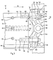
- FIG. 8 schematically shows a cooling system which comprises the channels 39, an exhaust pipe 51 and (for a pneumatic system) a fan or (for a hydraulic system) a pump 53.
- a connection to the suction pipe 51 is provided for each channel 39, which has been indicated schematically in FIG. 8 with pillar 55 and is to be described below in connection with the other figures.
- the cooling air can be drawn out of the spinning room and, if necessary, can be returned to the environment by the fan.
- a hydraulic system requires a closed circuit, as indicated by the dashed return pipe 55 in FIG. 8.
- a heat exchanger 57 must be provided in this circuit.
- the ambient air can serve as a heat sink. Where it is not desirable to use the spinning room air to "dispose" of the heat generated, the heat can be directed to another sink using the known principles of heat engineering. 8 can be integrated in the air conditioning system of the spinning mill.
- a pneumatic system can of course also comprise a closed circuit for the cooling air, in which case a heat exchanger similar to heat exchanger 57 becomes necessary.
- the cooling system can thus be isolated from the spinning room air, which may be desirable on the part of the cooling system (flight-loaded spinning room air) and / or the spinning room (conditioned air).
- another coolant for example a liquid coolant, can also be used.
- the cooling system can be integrated with the card's Trosh disposal system.
- Our European patent application No. 340458 shows e.g. a device for dusting a card, after which a movable air manifold is provided. This air manifold could e.g. also serve as a suction pipe 51 according to FIG. 8.
- the stationary sheet metal parts 33, 35, 37 are easily accessible. Accordingly, the (each) channel can easily follow a complicated course over the outer surface of the respective sheet metal part, care being taken to ensure that no deformation of the sheet metal parts is caused by an uneven temperature profile.
- FIG. 7B A simplified version of this system has been shown again in FIG. 7B, where each dirt separating device has been shown with two carding segments 41 and the sub-carding zone with a sheet metal casing 43. Since carding work must be carried out between the carding segments 41 and the drum, heat is generated in the corresponding zones of the working area. Each segment 41 is therefore provided with a respective channel 39 so that the heat generated can be dissipated as directly as possible. Under certain circumstances, it is then possible to forego heat transfer from the sheet metal casing. However, it can also be present, as has been indicated by dashed lines.
- FIG. 5 schematically shows a revolving cover arrangement with a multiplicity of individual T-shaped cover rods 45, of which each rod carries a set (not shown).
- the rods 45 are attached to endless supports (not shown) and moved together in the direction of movement R.
- Figure 6 shows that channels 47 can be formed between adjacent bars 45, e.g. by spanning the inner ends of the bars through a convertible top element 49. Through the channels 47, currents from a gaseous medium can possibly be generated during operation for heat dissipation.
- the main carding work is carried out on the first revolving lids above the material inlet (breeze), that is to say in zone Z (FIG. 5). It will usually suffice to dissipate heat from 6 to 12 bars in this zone (including the bar at the inlet end of the zone).
- the top element 49 can accordingly be short.
- Fig. 2 shows the adjoining segments 50, 42 on a larger scale.
- the simpler segment 50 comprises a first plate-shaped part 52 and a second plate-shaped part 54, which comprises two flat side sections 56 and a curved central section 58.
- the plate-shaped parts 52, 54 are connected to one another via side walls 60 and intermediate walls 62 in order to form three longitudinal channels 64.
- the segment extends with a constant cross-section over the entire width (axial length) of the reel 30 and it is fastened to the side plates of the card (card frame) using suitable fastening means (to be described below).
- the segment 50 is manufactured as an extruded profile made of light metal (e.g. aluminum). The shape of the segment enables a very thin-walled construction which nevertheless enables the required rigidity of the segment over the entire working width.
- the wall thickness of segment 50 can e.g. are in the range of 2 mm to 8 mm.
- the stiffness of the segment is important in order to keep a once defined setting of the fiber guide or fiber guide surface 66 as constant as possible over the entire working width in relation to the clothing mounted on the reel.
- This fiber guide surface 66 forms the outer jacket surface from the working area of the card over the angular range W corresponding to segment 50 (FIG. 1, shown for the identical segment 40) of the pre-carding zone (for the meaning of such an angular range see our German patent application 3835776).
- the stiffening of the fiber guide part 52 given by the plate-shaped part 54 enables close tolerances in the setting of this guide part to be maintained, despite the thin-walled construction, which results in weight and material savings.
- the more complicated segment 42 also includes an inner plate-shaped part 68 and an outer plate-shaped part 78. These parts are connected to one another by a side wall 72, a side wall 74 and an intermediate wall 76 to form two longitudinal channels 78.
- the segment 42 is also made as an extruded profile made of light metal. This design also gives segment 42 the advantages of low weight and high rigidity.
- the segment 42 does not serve directly as a fiber influencing element, but rather as a carrier for the actual working elements which are to be fixed to the part 68.
- Such Elements are well known to those skilled in the art and will therefore not be described in detail here.
- they comprise three rods 78A, 78B and 78C (indicated by dashed lines) which are fastened to the part 68 by screws (not shown).
- the fastening screws (not shown) for the upper rod 78C extend through a series of bores 80 (indicated by dashed lines, only one bore 80 is visible in FIG. 2) in the side wall 74.
- the side wall 72 is also provided with a series of holes 84 for receiving fastening screws for the lower rod 78C.
- the three rods can each be provided with a fiber-processing set, as has been shown, for example, in Swiss Patent No. 662804. This set can be, for example, a needle set, a saw tooth set or just a structured surface in accordance with our Swiss patent application No. 01092 / 89-5.
- the contact surfaces for the three rods on part 68 are matched to the curvature of the drum so that the width of each rod extends perpendicular to a respective radius of the drum when the segment is optimally adjusted.
- the side wall 72 is provided with an extension 86, which has a longitudinal groove 88 in its surface facing the segment 40.
- the groove 88 contains an elastomeric sealing element 90 or a hollow body.
- the segments 50, 42 and 40, 42 are mounted next to one another on the card in such a way that the sealing element 90 is in contact with a lip 92 on the segment 50, 40.
- the segment 50, 40 also has a longitudinal groove 94 next to the lip 92 and is provided with its own sealing element 96, which is also in contact with the sealing element 90 from the segment 42. Leakage flows between the segments (50) 40, 42 can thereby be largely prevented, which means better control over the air balance over the working area of the card. Thereby pollution of the environment of the drum is also avoided.
- the gaps between adjacent segments can also be sealed.
- the sealing element 96 already described also serves a further sealing element 98 (FIG. 2) in a groove 100 which opens in the opposite direction with respect to the groove 94.
- the wall 74 is also provided with an extension 102 which has a surface 104 which is oblique to the radial plane of the drum. This surface 104 can serve as a support surface for a dirt separating knife (106) (FIG. 3).
- the knife 106 has a through bore 108 and a screw 110 extends through this bore 108 into a threaded bore 110 (FIG. 2) in the extension 104 of the segment in order to fasten the knife to this extension.
- Fig. 3 shows part of a dirt separating device which can work, for example, according to the principle of the above-mentioned Swiss patent application No. 4103/88.
- This device comprises two segments, of which one segment 42 has already been described and the second segment 44 is very similar in construction to the first segment 42, but is mounted opposite the card in the opposite sense, so that the surface 104 (FIG. 2 ) from segment 42, faces a surface 104A from segment 44.
- the segment 44 has an abbreviated extension 102A and the two segments 42, 44 are placed side by side in such a way that a gap 112 between the two extensions 102, 102A remains open.
- This gap 112 serves as an access opening to a suction channel 114, which is held by a resilient holding element 116 in contact on the one hand with the surface 104A of the segment 44 and on the other hand with the knife 106.
- the holding element 116 is attached to the segment 44 by a suitable means (not shown).
- the suction channel 114 is in the form of a tube which extends over the entire working width of the card and is provided with an opening 118 opposite the gap 112.
- the mode of operation of this dirt separating device is generally known and will not be described in more detail here, since this invention is not directed towards the principle of the dirt separating method, but rather towards the construction of the dirt separating device.
- the suspension of the various elements on the frame of the card will now be described with reference to FIGS. 4 and 5.
- the segments 40, 50 can be attached to the frame without difficulty by means of fastening screws (not shown) and bores in the end parts of the segment.
- the accuracy of the manufacture of the segment and its rigidity make it possible to dispense with more complicated adjustment means.
- a special suspension with an adjusting means has been designed for the segments 42, 44, as will be described below with reference to FIGS. 4 and 5.
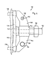
- FIG. 4 shows an end part of segment 42, viewed in the direction of arrow IV (FIG. 3), together with the corresponding suspension, which has been indicated generally by reference number 120.
- 5 shows the suspension alone, viewed in the direction of arrow 1V of FIG. 4.
- the end face 122 of the segment 42 is provided with two bores 124, 126 extending in the longitudinal direction of the segment.
- a bolt 128 is pressed into the bore 126 and thereby mounted in the segment 42.
- the other bore 124 serves to receive a second bolt 130, which forms part of the suspension 120, as will be explained in more detail below.
- the other end part of the segment 42 is also provided with two bores which each run coaxially with one bore 124, 126 and thus define two longitudinal axes 132, 134.
- the suspension 120 (see also FIG. 5) comprises a fastening plate 136 which is fastened to a bearing plate 140 of the card by screws 138.
- the plate 130 has a hub 142 with a bore (not indicated) which extends in the radial direction of the drum and which is provided with a thread.
- the suspension 120 further comprises an adjusting device with a hub part 144 and two wings 146, 148.
- the hub part 144 has a threaded through-bore (not particularly indicated) with a corresponding hollow adjusting screw 150.
- the annular end face of this adjusting screw 150 abuts the hub 142 from the mounting plate 136.
- a fixing screw 152 extends through the through hole of the set screw 150 to cooperate with the thread of the hub 142. When the fixing screw 152 is loosened, it is possible to change the setting of the hub part 144 relative to the fastening plate 136 by turning the adjusting screw 150. This newly defined setting can then be locked with the fixing screw 152.
- the wing 146 is provided with a slide bearing 154 for receiving the bolt 128.
- the wing 148 also has a slide bearing for receiving an axis 158 which is formed in one piece with the aforementioned bolt 130, but has a longitudinal axis 160 which is not in alignment with the axis 132, so that the parts 130, 158 together form an eccentric Form adjustment device.
- the part 158 is provided with an extension 162 for cooperation with an adjustment tool and with locking nuts 164.
- both bolts 128, 130 are moved in approximately radial directions with respect to the drum.
- This setting can be carried out in such a way, for example with the aid of a suitable teaching, that the clothing of the rod 78A adjacent to the pin 128 (for FIG. 2) is at a desired distance from the clothing of the drum. In all likelihood, however, the sets of the other two rods 78B and 78C are not at the desired distance from the drum set. However, the bolt 128 can still be actuated by the fixing screw 152 fixed in this setting.
- the desired setting of the other clothing rods is then achieved by rotating the eccentric device 130, 158, the axis 130 rotating about the axis 160 and thereby pivoting the segment 42 about the axis 134. Because the axis 134 lies vertically above the center point of the clothing strip 78A, the actuation of the eccentric has no significant influence on the setting of 78A.
- the overall setting can be fixed with locking screws 139, which extend through lugs 137 of the plate 136 into end parts 141 of the two wings 146, 148.
- the lugs 137 have slot-shaped holes to receive the screws
- Fig. 3 also shows an adjustment device for the knife 106, which is attached to the suspension for the segment 42.
- Each set screw 150 of this suspension carries a holding element 166 which carries a respective screw 168 adjustable in the holding element. This screw cooperates with a threaded bore (not indicated) provided in the end of the knife 106.
- the screw 168 in the holding element 166 By adjusting the screw 168 in the holding element 166, the free end of the knife 106 can be adjusted after loosening the fastening screws 110 relative to the clothing elements.
- the hole 108 in the knife 106 is therefore slit-shaped.
- FIG. 9 schematically shows a connection between a segment 50 (FIG. 2) or 40 (FIG. 1) and the suction pipe 51 (FIG. 8).
- segment 50 FIG. 2
- 40 For each segment 50, 40 there is a transition piece 180 which is adapted to the profile of the segment at one end and is provided with an elastic sealing element 182 at the other end.
- the sealing element connects a seal to the transition piece 180 and to the suction pipe 51, the element connecting to an access opening 184 in the pipe 51.
- the segments 42 present major problems because they cooperate with the hangers 120 at their ends. Transition pieces (not shown) can, however, either pass through the opening A (FIG. 3) of the end face 122 of the segment and the suspension 120 or through the opening B (FIG. 4) between the fastening plate 136 and the side of the suspension 120 facing this plate will. For this purpose, openings A and B can be enlarged.
- Heat could of course be dissipated from the drum formwork by generating a cooling air flow over the outer surface of the formwork, which flow could be separated from the hall air by an outer formwork of the machine.
- the targeted removal of heat from selected areas of the machine will prove to be significantly more effective.
Landscapes
- Engineering & Computer Science (AREA)
- Textile Engineering (AREA)
- Preliminary Treatment Of Fibers (AREA)
Applications Claiming Priority (2)
| Application Number | Priority Date | Filing Date | Title |
|---|---|---|---|
| CH437189 | 1989-12-06 | ||
| CH4371/89 | 1989-12-06 |
Publications (2)
| Publication Number | Publication Date |
|---|---|
| EP0431485A1 EP0431485A1 (de) | 1991-06-12 |
| EP0431485B1 true EP0431485B1 (de) | 1997-08-06 |
Family
ID=4274857
Family Applications (1)
| Application Number | Title | Priority Date | Filing Date |
|---|---|---|---|
| EP90122915A Revoked EP0431485B1 (de) | 1989-12-06 | 1990-11-30 | Kühlsystem |
Country Status (4)
| Country | Link |
|---|---|
| US (1) | US5127134A (ja) |
| EP (1) | EP0431485B1 (ja) |
| JP (1) | JPH03180517A (ja) |
| DE (1) | DE59010749D1 (ja) |
Cited By (4)
| Publication number | Priority date | Publication date | Assignee | Title |
|---|---|---|---|---|
| DE10325273A1 (de) * | 2003-06-03 | 2004-12-23 | Maschinenfabrik Rieter Ag | Anpassung der Kardeelementen an Wärmeausdehnungseffekten |
| DE102004035771A1 (de) * | 2004-07-23 | 2006-03-16 | Trützschler GmbH & Co KG | Vorrichtung an einer Karde mit einer Trommel, der Trommel gegenüberliegenden garnierten und/oder nichtgarnierten Elementen und ortsfesten Seitenteilen |
| DE102005029767A1 (de) * | 2005-06-24 | 2007-01-04 | TRüTZSCHLER GMBH & CO. KG | Vorrichtung an einer Spinnereivorbereitungsmaschine,insbesondere Karde, Krempel, Reiniger o. dgl., mit einem Kühlsystem |
| DE102010055290A1 (de) * | 2010-12-21 | 2012-06-21 | Trützschler GmbH & Co Kommanditgesellschaft | Vorrichtung an einer Karde oder Krempel, bei der mindestens ein Arbeits- und/oder Abdeckelement vorhanden ist |
Families Citing this family (12)
| Publication number | Priority date | Publication date | Assignee | Title |
|---|---|---|---|---|
| EP0497745A1 (en) * | 1991-01-28 | 1992-08-05 | Marcello Giuliani | Device for cooling the flat assembly in a card |
| IT1246971B (it) * | 1991-06-25 | 1994-12-01 | Marcello Giuliani | Carda cotoniera e per impieghi analoghi, con cappelli cardanti fissi che formano organi pulenti. |
| GB9120323D0 (en) * | 1991-09-24 | 1991-11-06 | Carding Spec Canada | Rotary member with internal cooling system |
| US5920961A (en) * | 1997-11-10 | 1999-07-13 | John D. Hollingsworth On Wheels, Inc. | Ventilating carding roll |
| DE19907288A1 (de) * | 1999-02-22 | 2000-08-24 | Rieter Ag Maschf | Karde |
| DE19925285B4 (de) * | 1999-06-02 | 2010-12-02 | TRüTZSCHLER GMBH & CO. KG | Vorrichtung an einer Karde mit einer Trommel, die eine zylindrische garnierte Mantelfläche und mindestens zwei radiale Tragelemente aufweist |
| DE10305048B4 (de) * | 2003-02-07 | 2014-02-06 | Trützschler GmbH & Co Kommanditgesellschaft | Vorrichtung an einer Karde zur Einstellung des Arbeitsabstandes zwischen der Trommel und mindestens einer benachbarten Walze |
| EP1697569B1 (de) * | 2003-06-03 | 2008-01-16 | Maschinenfabrik Rieter Ag | Auflagefläche auflageelement |
| DE102006014419B4 (de) | 2006-03-27 | 2021-04-15 | Trützschler GmbH & Co Kommanditgesellschaft | Vorrichtung an einer Spinnereivorbereitungsmaschine, insbesondere Karde, Krempel o. dgl., zur Einstellung des Kardierabstandes |
| DE102010055291A1 (de) * | 2010-12-21 | 2012-06-21 | Trützschler GmbH & Co Kommanditgesellschaft | Vorrichtung an einer Karde oder Krempel, bei der mindestens ein Arbeits- und/oder Abdeckelement angeordnet ist |
| ITTO20110165A1 (it) * | 2011-02-25 | 2012-08-26 | Oerlikon Neumag Italy S P A | Gruppo di lavorazione con sistema di raffreddamento, per una macchina per l'apertura di fibre, in particolare per una carda |
| CH720209A1 (de) * | 2022-11-08 | 2024-05-15 | Rieter Ag Maschf | Faserführungselement für eine Karde |
Family Cites Families (20)
| Publication number | Priority date | Publication date | Assignee | Title |
|---|---|---|---|---|
| GB191303173A (en) * | 1913-02-07 | 1913-12-04 | George Turnbull | An Improved Heating Apparatus with Syphon Drain for Carding Cylinders and Piece Drying Cylinders, also Cotton Drying Cylinders. |
| FR648333A (fr) * | 1927-06-15 | 1928-12-07 | Blanchisserie Et Teinturerie D | Rouleau exprimeur pneumatique |
| US2284750A (en) * | 1941-05-07 | 1942-06-02 | Spring Packing Corp | Delinting waste puller |
| CH261609A (de) * | 1946-11-21 | 1949-05-31 | Holmens Bruks & Fabriks Aktieb | Anlage bei Krempeln zum Entfernen des Abfalls auf pneumatischem Wege. |
| CH390109A (de) * | 1961-01-11 | 1965-03-31 | Rieter Ag Maschf | Radial luftdurchströmte, perforierte Trommel für Spinnereimaschinen |
| GB1141672A (en) * | 1966-03-02 | 1969-01-29 | Cotton Silk & Man Made Fibres | Improved air extraction system for carding engines |
| SU443944A1 (ru) * | 1973-02-13 | 1974-09-25 | Ленинградский институт текстильной и легкой промышленности им.С.М.Кирова | Направл ющее устройство шл почного полотна чесальной машины |
| DE2508265C3 (de) * | 1975-02-26 | 1978-08-10 | Fried. Krupp Gmbh, 4300 Essen | Verfahren und Vorrichtung zur Erzielung eines einwandfreien Flor-Randes bei Verarbeitung insbesondere von Feinfasern auf Krempeln oder Karden |
| DE2833413A1 (de) * | 1977-08-09 | 1979-02-22 | Platt Saco Lowell Ltd | Textilkarde |
| US4198731A (en) * | 1977-10-31 | 1980-04-22 | John D. Hollingsworth On Wheels, Inc. | Carding machine cleaning apparatus |
| CH629544A5 (de) * | 1978-04-25 | 1982-04-30 | Rieter Ag Maschf | Verfahren zur steuerung der arbeitsverhaeltnisse in einer verarbeitungsmaschine der stapelfaserspinnerei und vorrichtung zur durchfuehrung des verfahrens. |
| DE2966310D1 (en) * | 1978-11-07 | 1983-11-17 | Rieter Ag Maschf | Apparatus for strepping the flats of a card |
| US4227285A (en) * | 1979-02-02 | 1980-10-14 | Marvin Hamrick | Textile card cleaning apparatus |
| DE2950367C2 (de) * | 1979-12-14 | 1982-07-15 | Trützschler GmbH & Co KG, 4050 Mönchengladbach | Karde oder Krempel mit einer Umkleidung |
| DE3270141D1 (en) * | 1981-10-10 | 1986-04-30 | Carding Spec Canada | Carding engine |
| DE8417960U1 (de) * | 1984-06-14 | 1984-09-27 | Ramisch Kleinewefers Gmbh, 4150 Krefeld | Schnellaufende krempel zur vliesbildung aus thermoplastischen fasern |
| CH662804A5 (en) * | 1985-01-31 | 1987-10-30 | Paul Mueller | Apparatus for the silver treatment of fresh water or utility water for sterilising the water |
| EP0340458B1 (de) * | 1988-04-29 | 1993-08-11 | Maschinenfabrik Rieter Ag | Vorrichtung zum Entstauben einer Karde |
| DE3835776A1 (de) * | 1988-10-20 | 1990-04-26 | Rieter Ag Maschf | Karde mit modularer unterteilung der kardierzonen |
| CN1022337C (zh) * | 1989-03-23 | 1993-10-06 | 里特机械公司 | 纤维网除尘器 |
-
1990
- 1990-11-27 JP JP2321349A patent/JPH03180517A/ja active Pending
- 1990-11-30 DE DE59010749T patent/DE59010749D1/de not_active Revoked
- 1990-11-30 EP EP90122915A patent/EP0431485B1/de not_active Revoked
- 1990-12-05 US US07/622,619 patent/US5127134A/en not_active Expired - Fee Related
Cited By (6)
| Publication number | Priority date | Publication date | Assignee | Title |
|---|---|---|---|---|
| DE10325273A1 (de) * | 2003-06-03 | 2004-12-23 | Maschinenfabrik Rieter Ag | Anpassung der Kardeelementen an Wärmeausdehnungseffekten |
| DE102004035771A1 (de) * | 2004-07-23 | 2006-03-16 | Trützschler GmbH & Co KG | Vorrichtung an einer Karde mit einer Trommel, der Trommel gegenüberliegenden garnierten und/oder nichtgarnierten Elementen und ortsfesten Seitenteilen |
| US7694393B2 (en) | 2004-07-23 | 2010-04-13 | Truetzschler Gmbh & Co. Kg | Apparatus at a carding machine having a cylinder and clothed and/or unclothed elements located opposite the cylinder |
| DE102005029767A1 (de) * | 2005-06-24 | 2007-01-04 | TRüTZSCHLER GMBH & CO. KG | Vorrichtung an einer Spinnereivorbereitungsmaschine,insbesondere Karde, Krempel, Reiniger o. dgl., mit einem Kühlsystem |
| US7614122B2 (en) | 2005-06-24 | 2009-11-10 | Truetzschler Gmbh & Co. Kg | Apparatus on a spinning preparation machine, especially a flat card, roller card, cleaner or the like, with a cooling system |
| DE102010055290A1 (de) * | 2010-12-21 | 2012-06-21 | Trützschler GmbH & Co Kommanditgesellschaft | Vorrichtung an einer Karde oder Krempel, bei der mindestens ein Arbeits- und/oder Abdeckelement vorhanden ist |
Also Published As
| Publication number | Publication date |
|---|---|
| JPH03180517A (ja) | 1991-08-06 |
| US5127134A (en) | 1992-07-07 |
| EP0431485A1 (de) | 1991-06-12 |
| DE59010749D1 (de) | 1997-09-11 |
Similar Documents
| Publication | Publication Date | Title |
|---|---|---|
| EP0431485B1 (de) | Kühlsystem | |
| EP2049840B1 (de) | Brennkammer einer verbrennungsanlage | |
| EP0638418B1 (de) | Temperierungssystem für Druckmaschinenzylinder | |
| EP0122464A2 (de) | Spinnkopf zum Schmelzspinnen endloser Fäden | |
| DE19649073C2 (de) | Vorrichtung zur Abkühlung von Strangpreßprofilen | |
| EP0431482A1 (de) | Tambourverschalungssegment | |
| EP0745158B1 (de) | Dampfblaskasten | |
| EP1031650B1 (de) | Karde. | |
| EP0619391A1 (de) | Eintragsystem für eine Luftwebmaschine | |
| EP0849079B1 (de) | Trocknereinheit | |
| DE19516653C1 (de) | Rotationsdruckmaschine mit abschwenkbaren Gummizylindern | |
| AT407720B (de) | Giesswalze für kontinuierlichen guss mit gegenläufigen walzen für dünne stärken | |
| EP0150300B1 (de) | Farbwerk für eine Druckmaschine | |
| EP0391266B1 (de) | Wärmetauscher | |
| EP0650776B1 (de) | Vorrichtung zum Kühlen von Walzbändern | |
| DE4402278C2 (de) | Vorrichtung zum Aufbringen von Dampf | |
| DE8807768U1 (de) | Schaltschrankwand | |
| DE2917897A1 (de) | Drehtrommel-vakuumfilter | |
| EP0864262A2 (de) | Vorrichtung zum Verkleben flächiger Materialien und Hohlprofil-Heizkörper für eine solche Vorrichtung | |
| DE102007000865B4 (de) | Druckeinheit mit mindestens zwei relativ zueinander in einer horizontalen Richtung abstandsveränderbaren Seitengestellteilen | |
| DE3546535C2 (ja) | ||
| DE8805176U1 (de) | Kühlvorrichtung für eine bedruckte Bahn | |
| DE3305989A1 (de) | Vorrichtung zum waermeaustausch | |
| EP2185361B1 (de) | Druckeinheit mit mindestens zwei relativ zueinander in einer horizontalen richtung abstandsveränderbaren seitengestellteilen | |
| DE1942790C (de) | Düsenkasten fur Turbinen mit geteil tem Gehäuse |
Legal Events
| Date | Code | Title | Description |
|---|---|---|---|
| PUAI | Public reference made under article 153(3) epc to a published international application that has entered the european phase |
Free format text: ORIGINAL CODE: 0009012 |
|
| AK | Designated contracting states |
Kind code of ref document: A1 Designated state(s): CH DE FR GB IT LI |
|
| 17P | Request for examination filed |
Effective date: 19910418 |
|
| 17Q | First examination report despatched |
Effective date: 19930528 |
|
| GRAG | Despatch of communication of intention to grant |
Free format text: ORIGINAL CODE: EPIDOS AGRA |
|
| GRAH | Despatch of communication of intention to grant a patent |
Free format text: ORIGINAL CODE: EPIDOS IGRA |
|
| GRAH | Despatch of communication of intention to grant a patent |
Free format text: ORIGINAL CODE: EPIDOS IGRA |
|
| GRAA | (expected) grant |
Free format text: ORIGINAL CODE: 0009210 |
|
| AK | Designated contracting states |
Kind code of ref document: B1 Designated state(s): CH DE FR GB IT LI |
|
| PG25 | Lapsed in a contracting state [announced via postgrant information from national office to epo] |
Ref country code: FR Free format text: LAPSE BECAUSE OF FAILURE TO SUBMIT A TRANSLATION OF THE DESCRIPTION OR TO PAY THE FEE WITHIN THE PRESCRIBED TIME-LIMIT Effective date: 19970806 |
|
| REG | Reference to a national code |
Ref country code: CH Ref legal event code: EP |
|
| REF | Corresponds to: |
Ref document number: 59010749 Country of ref document: DE Date of ref document: 19970911 |
|
| ITF | It: translation for a ep patent filed | ||
| GBT | Gb: translation of ep patent filed (gb section 77(6)(a)/1977) |
Effective date: 19970919 |
|
| PG25 | Lapsed in a contracting state [announced via postgrant information from national office to epo] |
Ref country code: LI Free format text: LAPSE BECAUSE OF NON-PAYMENT OF DUE FEES Effective date: 19971130 Ref country code: CH Free format text: LAPSE BECAUSE OF NON-PAYMENT OF DUE FEES Effective date: 19971130 |
|
| EN | Fr: translation not filed | ||
| PLBI | Opposition filed |
Free format text: ORIGINAL CODE: 0009260 |
|
| 26 | Opposition filed |
Opponent name: TRUETZSCHLER GMBH & CO. KG Effective date: 19980406 |
|
| PLBF | Reply of patent proprietor to notice(s) of opposition |
Free format text: ORIGINAL CODE: EPIDOS OBSO |
|
| REG | Reference to a national code |
Ref country code: CH Ref legal event code: PL |
|
| PGFP | Annual fee paid to national office [announced via postgrant information from national office to epo] |
Ref country code: GB Payment date: 19981027 Year of fee payment: 9 Ref country code: DE Payment date: 19981027 Year of fee payment: 9 |
|
| PLBF | Reply of patent proprietor to notice(s) of opposition |
Free format text: ORIGINAL CODE: EPIDOS OBSO |
|
| PLBF | Reply of patent proprietor to notice(s) of opposition |
Free format text: ORIGINAL CODE: EPIDOS OBSO |
|
| PLBF | Reply of patent proprietor to notice(s) of opposition |
Free format text: ORIGINAL CODE: EPIDOS OBSO |
|
| RDAH | Patent revoked |
Free format text: ORIGINAL CODE: EPIDOS REVO |
|
| RDAG | Patent revoked |
Free format text: ORIGINAL CODE: 0009271 |
|
| STAA | Information on the status of an ep patent application or granted ep patent |
Free format text: STATUS: PATENT REVOKED |
|
| 27W | Patent revoked |
Effective date: 19991112 |
|
| GBPR | Gb: patent revoked under art. 102 of the ep convention designating the uk as contracting state |
Free format text: 991112 |