EP0432336A1 - Device for injecting additive products into a liquid - Google Patents
Device for injecting additive products into a liquid Download PDFInfo
- Publication number
- EP0432336A1 EP0432336A1 EP89403434A EP89403434A EP0432336A1 EP 0432336 A1 EP0432336 A1 EP 0432336A1 EP 89403434 A EP89403434 A EP 89403434A EP 89403434 A EP89403434 A EP 89403434A EP 0432336 A1 EP0432336 A1 EP 0432336A1
- Authority
- EP
- European Patent Office
- Prior art keywords
- bell
- chamber
- liquid
- conduit
- nozzle
- Prior art date
- Legal status (The legal status is an assumption and is not a legal conclusion. Google has not performed a legal analysis and makes no representation as to the accuracy of the status listed.)
- Granted
Links
- 239000007788 liquid Substances 0.000 title claims abstract description 44
- 239000000654 additive Substances 0.000 title claims abstract description 20
- 230000000996 additive effect Effects 0.000 title claims abstract description 19
- 239000012530 fluid Substances 0.000 claims abstract description 16
- 238000004891 communication Methods 0.000 claims abstract description 4
- 239000000047 product Substances 0.000 claims description 18
- 239000002244 precipitate Substances 0.000 claims description 14
- 239000000463 material Substances 0.000 claims description 8
- 239000012780 transparent material Substances 0.000 claims 1
- 150000003839 salts Chemical class 0.000 abstract description 8
- 230000015572 biosynthetic process Effects 0.000 abstract description 2
- 239000007789 gas Substances 0.000 description 14
- 238000002347 injection Methods 0.000 description 11
- 239000007924 injection Substances 0.000 description 11
- XLYOFNOQVPJJNP-UHFFFAOYSA-N water Substances O XLYOFNOQVPJJNP-UHFFFAOYSA-N 0.000 description 8
- ZAMOUSCENKQFHK-UHFFFAOYSA-N Chlorine atom Chemical compound [Cl] ZAMOUSCENKQFHK-UHFFFAOYSA-N 0.000 description 5
- 239000000460 chlorine Substances 0.000 description 5
- 229910052801 chlorine Inorganic materials 0.000 description 5
- 230000000007 visual effect Effects 0.000 description 5
- 238000009434 installation Methods 0.000 description 3
- 238000010923 batch production Methods 0.000 description 2
- 238000002955 isolation Methods 0.000 description 2
- 230000007935 neutral effect Effects 0.000 description 2
- 238000005086 pumping Methods 0.000 description 2
- 239000007787 solid Substances 0.000 description 2
- 238000012795 verification Methods 0.000 description 2
- OYPRJOBELJOOCE-UHFFFAOYSA-N Calcium Chemical compound [Ca] OYPRJOBELJOOCE-UHFFFAOYSA-N 0.000 description 1
- 229920000297 Rayon Polymers 0.000 description 1
- 238000009825 accumulation Methods 0.000 description 1
- 239000011575 calcium Substances 0.000 description 1
- 229910052791 calcium Inorganic materials 0.000 description 1
- 230000008859 change Effects 0.000 description 1
- 238000006243 chemical reaction Methods 0.000 description 1
- 150000001875 compounds Chemical class 0.000 description 1
- 238000007906 compression Methods 0.000 description 1
- 230000001186 cumulative effect Effects 0.000 description 1
- 230000001419 dependent effect Effects 0.000 description 1
- 230000008021 deposition Effects 0.000 description 1
- 239000000499 gel Substances 0.000 description 1
- 230000005484 gravity Effects 0.000 description 1
- 239000000203 mixture Substances 0.000 description 1
- 230000004048 modification Effects 0.000 description 1
- 238000012986 modification Methods 0.000 description 1
- 238000011197 physicochemical method Methods 0.000 description 1
- 238000000746 purification Methods 0.000 description 1
- 230000009467 reduction Effects 0.000 description 1
- 238000003466 welding Methods 0.000 description 1
Images

Classifications
-
- B—PERFORMING OPERATIONS; TRANSPORTING
- B01—PHYSICAL OR CHEMICAL PROCESSES OR APPARATUS IN GENERAL
- B01J—CHEMICAL OR PHYSICAL PROCESSES, e.g. CATALYSIS OR COLLOID CHEMISTRY; THEIR RELEVANT APPARATUS
- B01J4/00—Feed or outlet devices; Feed or outlet control devices
-
- B—PERFORMING OPERATIONS; TRANSPORTING
- B01—PHYSICAL OR CHEMICAL PROCESSES OR APPARATUS IN GENERAL
- B01F—MIXING, e.g. DISSOLVING, EMULSIFYING OR DISPERSING
- B01F23/00—Mixing according to the phases to be mixed, e.g. dispersing or emulsifying
- B01F23/20—Mixing gases with liquids
- B01F23/23—Mixing gases with liquids by introducing gases into liquid media, e.g. for producing aerated liquids
- B01F23/234—Surface aerating
-
- B—PERFORMING OPERATIONS; TRANSPORTING
- B01—PHYSICAL OR CHEMICAL PROCESSES OR APPARATUS IN GENERAL
- B01F—MIXING, e.g. DISSOLVING, EMULSIFYING OR DISPERSING
- B01F23/00—Mixing according to the phases to be mixed, e.g. dispersing or emulsifying
- B01F23/20—Mixing gases with liquids
- B01F23/23—Mixing gases with liquids by introducing gases into liquid media, e.g. for producing aerated liquids
- B01F23/234—Surface aerating
- B01F23/2341—Surface aerating by cascading, spraying or projecting a liquid into a gaseous atmosphere
- B01F23/23413—Surface aerating by cascading, spraying or projecting a liquid into a gaseous atmosphere using nozzles for projecting the liquid into the gas atmosphere
-
- B—PERFORMING OPERATIONS; TRANSPORTING
- B01—PHYSICAL OR CHEMICAL PROCESSES OR APPARATUS IN GENERAL
- B01F—MIXING, e.g. DISSOLVING, EMULSIFYING OR DISPERSING
- B01F23/00—Mixing according to the phases to be mixed, e.g. dispersing or emulsifying
- B01F23/40—Mixing liquids with liquids; Emulsifying
- B01F23/45—Mixing liquids with liquids; Emulsifying using flow mixing
- B01F23/451—Mixing liquids with liquids; Emulsifying using flow mixing by injecting one liquid into another
-
- B—PERFORMING OPERATIONS; TRANSPORTING
- B01—PHYSICAL OR CHEMICAL PROCESSES OR APPARATUS IN GENERAL
- B01F—MIXING, e.g. DISSOLVING, EMULSIFYING OR DISPERSING
- B01F25/00—Flow mixers; Mixers for falling materials, e.g. solid particles
- B01F25/20—Jet mixers, i.e. mixers using high-speed fluid streams
-
- B—PERFORMING OPERATIONS; TRANSPORTING
- B01—PHYSICAL OR CHEMICAL PROCESSES OR APPARATUS IN GENERAL
- B01F—MIXING, e.g. DISSOLVING, EMULSIFYING OR DISPERSING
- B01F25/00—Flow mixers; Mixers for falling materials, e.g. solid particles
- B01F25/30—Injector mixers
- B01F25/32—Injector mixers wherein the additional components are added in a by-pass of the main flow
-
- C—CHEMISTRY; METALLURGY
- C02—TREATMENT OF WATER, WASTE WATER, SEWAGE, OR SLUDGE
- C02F—TREATMENT OF WATER, WASTE WATER, SEWAGE, OR SLUDGE
- C02F1/00—Treatment of water, waste water, or sewage
- C02F1/68—Treatment of water, waste water, or sewage by addition of specified substances, e.g. trace elements, for ameliorating potable water
- C02F1/685—Devices for dosing the additives
- C02F1/686—Devices for dosing liquid additives
-
- B—PERFORMING OPERATIONS; TRANSPORTING
- B01—PHYSICAL OR CHEMICAL PROCESSES OR APPARATUS IN GENERAL
- B01F—MIXING, e.g. DISSOLVING, EMULSIFYING OR DISPERSING
- B01F33/00—Other mixers; Mixing plants; Combinations of mixers
- B01F33/70—Mixers specially adapted for working at sub- or super-atmospheric pressure, e.g. combined with de-foaming
-
- B—PERFORMING OPERATIONS; TRANSPORTING
- B01—PHYSICAL OR CHEMICAL PROCESSES OR APPARATUS IN GENERAL
- B01F—MIXING, e.g. DISSOLVING, EMULSIFYING OR DISPERSING
- B01F33/00—Other mixers; Mixing plants; Combinations of mixers
- B01F33/70—Mixers specially adapted for working at sub- or super-atmospheric pressure, e.g. combined with de-foaming
- B01F33/71—Mixers specially adapted for working at sub- or super-atmospheric pressure, e.g. combined with de-foaming working at super-atmospheric pressure, e.g. in pressurised vessels
-
- Y—GENERAL TAGGING OF NEW TECHNOLOGICAL DEVELOPMENTS; GENERAL TAGGING OF CROSS-SECTIONAL TECHNOLOGIES SPANNING OVER SEVERAL SECTIONS OF THE IPC; TECHNICAL SUBJECTS COVERED BY FORMER USPC CROSS-REFERENCE ART COLLECTIONS [XRACs] AND DIGESTS
- Y10—TECHNICAL SUBJECTS COVERED BY FORMER USPC
- Y10T—TECHNICAL SUBJECTS COVERED BY FORMER US CLASSIFICATION
- Y10T137/00—Fluid handling
- Y10T137/2931—Diverse fluid containing pressure systems
- Y10T137/3115—Gas pressure storage over or displacement of liquid
- Y10T137/3127—With gas maintenance or application
-
- Y—GENERAL TAGGING OF NEW TECHNOLOGICAL DEVELOPMENTS; GENERAL TAGGING OF CROSS-SECTIONAL TECHNOLOGIES SPANNING OVER SEVERAL SECTIONS OF THE IPC; TECHNICAL SUBJECTS COVERED BY FORMER USPC CROSS-REFERENCE ART COLLECTIONS [XRACs] AND DIGESTS
- Y10—TECHNICAL SUBJECTS COVERED BY FORMER USPC
- Y10T—TECHNICAL SUBJECTS COVERED BY FORMER US CLASSIFICATION
- Y10T137/00—Fluid handling
- Y10T137/8158—With indicator, register, recorder, alarm or inspection means
- Y10T137/8342—Liquid level responsive indicator, recorder or alarm
-
- Y—GENERAL TAGGING OF NEW TECHNOLOGICAL DEVELOPMENTS; GENERAL TAGGING OF CROSS-SECTIONAL TECHNOLOGIES SPANNING OVER SEVERAL SECTIONS OF THE IPC; TECHNICAL SUBJECTS COVERED BY FORMER USPC CROSS-REFERENCE ART COLLECTIONS [XRACs] AND DIGESTS
- Y10—TECHNICAL SUBJECTS COVERED BY FORMER USPC
- Y10T—TECHNICAL SUBJECTS COVERED BY FORMER US CLASSIFICATION
- Y10T137/00—Fluid handling
- Y10T137/8593—Systems
- Y10T137/87571—Multiple inlet with single outlet
Definitions
- the present invention relates to a device for injecting additive products into a liquid.
- the present invention provides a device for injecting additive products into a liquid continuously flowing through a conduit.
- Said device comprises a nozzle for injecting the additive product and is characterized in that it includes a bell delimiting a chamber which is filled with a gas under pressure and is in fluid communication with said conduit through which the liquid flows.
- the injection nozzle is provided within the bell at a predetermined distance from a constant liquid level whereby the injection nozzle is located entirely in the portion of the chamber filled with the gas under pressure.
- the liquid being treated does not contact the injection nozzle, thus precluding the deposition of insoluble salts thereon which may form during the injection of the additive products into the liquid. It can be seen, therefore, that there is no longer any possibility for such salts to precipitate in such a way as to form concretions on the injection nozzle.
- the gaseous atmosphere can comprise air, a neutral gas or a mixture of gases.
- Means for introducing and maintaining the gaseous atmosphere may consist, in the simplest case, in a fitting issuing into the chamber and equipped with a shut off valve.
- the fitting may be permanently or temporarily connected to a source of compressed air or gas. Control of the shut off valve or of the start up of the source of the compressed air or gas may be manual or automatic.
- all or part of the walls forming the chamber may be made of transparent or translucent material affording visual verification of the liquid level under the gaseous atmosphere.
- a level detector of any suitable type may be installed in the chamber, which would set off a visual or accoustic warning signal, or which may be connected to an automatic level control system.
- the gas used in conjunction with the present invention is preferably insoluble or only slightly soluble in the liquid being treated, thus affording entirely manual control of the liquid level in the bell.
- the device may comprise a separator for removing precipitates deposited in or on the fluid conduit.
- a separator for removing precipitates deposited in or on the fluid conduit.
- any suitable separator may be used such as filters, centrifugal or cyclone separators, decantors, etc.
- the several elements, a length of liquid conduit, the chamber, the nozzle and the gas fill fitting, which constitute the invention may form an independent unit which can be inserted in liquid piping and connected to a dosing pump for additive products, or may be integrated into a complete dosing unit.
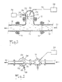
- the device 10, of which Figure 1 is a sectional view, comprises a length of conduit 12 having two end flanges 14 or any other suitable connecting means, by which it may be inserted in the piping 16 through which flows a liquid 18 in the direction indicated by arrow 20 in Figure 1.
- the device comprises a bell 22, the interior of which defines a chamber 24 in fluid communication with the conduit.
- the bell may be formed as a separate piece and fixed to the length of conduit 12 by suitable flanges, as illustrated in Figure 1, or according to a variant of the invention, not shown, may be made of the same material as the length of conduit and fixed to the latter for example by welding.
- the nozzle 26 for injecting additive products into the liquid 18 projects inside the chamber 24.
- additive products are fed from a pumping and dosing group 28 through a tube 30.
- the chamber 24 is filled with a gaseous atmosphere under pressure whereby the nozzle extends entirely into the gaseous atmosphere and the level 32 of the liquid in the chamber remains at a predetermined distance below the tip of the nozzle.
- the quantity of gas required in the chamber is introduced, and, if need be, maintained, by means of a fitting 34 issuing into the chamber, and which may be connected either permanently or temporarily to a compressed gas source 36.
- a shut off valve 38 is provided on the fitting and affords isolation of the chamber from the source 36 or the ambient atmosphere.
- the bell may be completely formed from a transparent or translucent material in order to afford visual verification of the liquid level 32, and may include one or more level indicators 40.
- the bell may be only partially made of such a material, at least in a zone extending sufficiently vertically to permit effective visual checking of the liquid level.
- the shut off valve shown is of the manually operated type and can as such be opened by an operator for instance, when the liquid level rises above a predetermined point or set maximum height, in order to allow a certain quantity of pressurized gas to enter the chamber from the source 36 and to decrease the level of the liquid to a predetermined low point.
- the shut off valve 38 may be a check valve : in such case, the operator would control the start up and the shut off of the pressure source 36 in order to re-establish the desired liquid level.
- the maintaining of the liquid level can be made automatic, for instance, by allowing the valve 38 to take the form of a float valve, or of a motorized valve controlled by a pilot operated control unit which itself is linked to appropriate level detectors.
- the gas selected is preferably insoluble or only very slightly soluble in the liquid being treated, and is advantageously a neutral gas allowing the use of a visual level control arrangement and of a manually operated valve in the majority of applications, as pumping and dosing groups for additive products generally require regular surveillance.
- Figure 2 shows the device represented in Figure 1 and described hereinabove associated, according to the invention, with a precipitate separator situated downstream in the direction of fluid flow indicated by arrow 20 in Figure 2.
- the separator shown is of the centrifugal type, and includes a frusto-conical shell or housing 52 with a vertical axis, in which the liquid enters through a substantially tangential orifice 54, and exits from the housing 52 through a substantially central orifice 56 situated in the upper part of the housing.
- Such an arrangement allows insoluble precipitates which may form in the injection device 10 to accumulate along the periphery of the housing 52 by centrifugal force and to be displaced by gravity to the lower part of the frusto-conical housing.
- An evacuation tube 58 provided with a valve 60 issues into the lower part of the housing in order to afford evacuation of precipitate matter therefrom at regular intervals.
- an additional decanting and gas dosage chamber 62 is provided beneath the bell 22.
- the volume of the chamber 62 affords a reduction in the flow rate of the liquid entering through an inlet orifice 64 and exiting through an outlet orifice 66, and therefore allowing the settling of precipitates at the bottom 68 of the chamber 62.
- the baffle 70 is provided in the chamber and forms a flow space 72 adjacent the bottom of the chamber. As the liquid flow undergoes a change in direction of between 90° and 180°, the precipitates are deposited on the bottom of the chamber.
- a shut off valve 74 placed adjacent to the inlet orifice 64 allows for the isolation of the chamber 62 and the bell 22 and evacuation valve 76 provided in a conduit 78 issuing through the bottom of chamber 62 allows for draining of the latter.
- the foregoing arrangement provides for two functions : - firstly it enables accumulated precipitates to be evacuated from the bottom of the chamber ; and, - secondly, it allows air to be injected into said chamber in order to maintain the level of air in the bell 22.
- the cumulative volume of the bell and the chamber should be determined as a function of the working pressure of the liquid circuit, in order for the re-compression of the volume of air contained in the bell and the chamber to result in the establishment of the desired level of fluid in the lower part of the bell 22 once the system is brought back into operation by the opening of shut off valve 74.
- centrifugal separator 50 may be replaced by any other suitable type of separator.
- the positioning of the bell 22 above the conduit 12 is not to be limited to the arrangements shown in Figures 1 and 3.
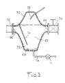
- the primary fluid conduit 12 may include a branch conduit 82 coupled to the primary fluid conduit and disposed in a loop in parallel to a section of the latter.
- a back pressure means shown as an annular disc 86 in Figure 4 is provided in a primary fluid conduit 12 in order to cause a fraction of the fluid flowing therein to be diverted through the branch conduit 82, as represented by arrow 84 in Figure 4.
- back pressure means shown in Figure 4 is a fixed resistance, stationary device, it will be appreciated that any suitable mobile and/or adjustable arrangement may be used to divert a fraction of the fluid flow into branch conduit 82.
- the portion of the fluid to be treated which enters the branch conduit 82 is treated with additive product exactly as set forth hereinabove, and is subsequently channeled back to the primary conduit 12 where the treated portion of the fluid mixes with the portion of the fluid which was not diverted through the branch conduit.
- additive products should not be understood in a restrictive way, but include all products for treatment, purification, softening, coloration or decoloration, Ph or surface tension modification, etc, of a liquid.
- precipitate is taken to mean all bodies, either solid or semi-solid, such as flocculent materials, gels, viscose products, etc.
Landscapes
- Chemical & Material Sciences (AREA)
- Chemical Kinetics & Catalysis (AREA)
- Organic Chemistry (AREA)
- Hydrology & Water Resources (AREA)
- Medicinal Chemistry (AREA)
- Life Sciences & Earth Sciences (AREA)
- Health & Medical Sciences (AREA)
- Engineering & Computer Science (AREA)
- Environmental & Geological Engineering (AREA)
- Water Supply & Treatment (AREA)
- Physical Or Chemical Processes And Apparatus (AREA)
- Loading And Unloading Of Fuel Tanks Or Ships (AREA)
- Degasification And Air Bubble Elimination (AREA)
Abstract
Above the section of conduit (12), the device comprises a bell (22), the interior of which defines a chamber (24) in fluid communication with the conduit.
A nozzle (26) for injecting additive products into the liquid (18) projects inside the chamber (24).
In order to remove the nozzle (26) from contact with the liquid (18) and thereby avoid formation on or about the nozzle of insoluble salt deposits, the changer (24) is filled with a gaseous atmosphere under pressure in order to maintain the level (32) of the liquid in the chamber at a predetermined distance below the tip of the nozzle (26).
Description
- The present invention relates to a device for injecting additive products into a liquid.
- Numerous applications are known in which additive products must be injected into a liquid, for example, in water treatment installations or facilities in which chlorine is injected to render source water potable.
- Due to the presence of various salts or compounds dissolved in the water, or the liquid, the injection of chlorine, or other additives, causes chemical reactions which produce insoluble or only slightly soluble salts which precipitate at least partially from the liquid, as in the cited example, calcium may precipitate from treated water.
- These insoluble salts often precipitate onto the additive product injection nozzle, or in regions adjacent thereto, and accumulate to form undesirable deposits or concretions capable of obstructing the injection nozzle, or even the conduit through which the liquid flows. Certain sensitive parts of such installations must therefore be dismantled in order to eliminate such deposits at regular intervals, by suitable physico-chemical methods.
- Moreover, devices have been proposed for adding chlorine to water in a batch process, by suction produced by the evacuation of a treated water holding tank as water is drawn therefrom. Such a device is described in U.S. patent N° 2,418,628. Although in such known devices the problem of accumulation of precipitated salts on the tube through which chlorine is added is not normally posed, such devices are wholly unsuitable for continuous operation as is required of water treatment facilities, as the operation of the chlorine injection circuit is entirely dependent on pressure fluctuations only existing in a batch process installation.
- In order to alleviate the drawbacks of existing devices, the present invention provides a device for injecting additive products into a liquid continuously flowing through a conduit. Said device comprises a nozzle for injecting the additive product and is characterized in that it includes a bell delimiting a chamber which is filled with a gas under pressure and is in fluid communication with said conduit through which the liquid flows. Furthermore, the injection nozzle is provided within the bell at a predetermined distance from a constant liquid level whereby the injection nozzle is located entirely in the portion of the chamber filled with the gas under pressure.
- By virtue of the invention, the liquid being treated does not contact the injection nozzle, thus precluding the deposition of insoluble salts thereon which may form during the injection of the additive products into the liquid. It can be seen, therefore, that there is no longer any possibility for such salts to precipitate in such a way as to form concretions on the injection nozzle.
- According to the nature of the liquid and/or of the additive products in the application envisaged, the gaseous atmosphere can comprise air, a neutral gas or a mixture of gases.
- Means for introducing and maintaining the gaseous atmosphere may consist, in the simplest case, in a fitting issuing into the chamber and equipped with a shut off valve. The fitting may be permanently or temporarily connected to a source of compressed air or gas. Control of the shut off valve or of the start up of the source of the compressed air or gas may be manual or automatic.
- In order to verify that the gaseous atmosphere occupies a volume sufficient to entirely contain the nozzle, all or part of the walls forming the chamber may be made of transparent or translucent material affording visual verification of the liquid level under the gaseous atmosphere. Alternatively, a level detector of any suitable type may be installed in the chamber, which would set off a visual or accoustic warning signal, or which may be connected to an automatic level control system.
- The gas used in conjunction with the present invention is preferably insoluble or only slightly soluble in the liquid being treated, thus affording entirely manual control of the liquid level in the bell.
- Furthermore, the device may comprise a separator for removing precipitates deposited in or on the fluid conduit. For the purpose of the invention any suitable separator may be used such as filters, centrifugal or cyclone separators, decantors, etc.
- The several elements, a length of liquid conduit, the chamber, the nozzle and the gas fill fitting, which constitute the invention may form an independent unit which can be inserted in liquid piping and connected to a dosing pump for additive products, or may be integrated into a complete dosing unit.
- Various details and advantages of the invention will be better understood through the following description in which reference is made to the annexed drawings, in which :
- Figure 1 is a schematic sectional view of a device according to the invention,
- Figure 2 is a schematic plan view of the device of Figure 1, shown connected to a centrifugal precipitate separator,
- Figure 3 is a schematic sectional view of an alternative embodiment of the invention, and
- Figure 4 is a schematic sectional view of a second alternative embodiment of the invention.
- The
device 10, of which Figure 1 is a sectional view, comprises a length ofconduit 12 having twoend flanges 14 or any other suitable connecting means, by which it may be inserted in thepiping 16 through which flows aliquid 18 in the direction indicated byarrow 20 in Figure 1. - Above the section of
conduit 12, the device comprises abell 22, the interior of which defines achamber 24 in fluid communication with the conduit. The bell may be formed as a separate piece and fixed to the length ofconduit 12 by suitable flanges, as illustrated in Figure 1, or according to a variant of the invention, not shown, may be made of the same material as the length of conduit and fixed to the latter for example by welding. - The
nozzle 26 for injecting additive products into the liquid 18 projects inside thechamber 24. - As is schematically represented in the Figures, additive products are fed from a pumping and
dosing group 28 through atube 30. - In order to remove the
nozzle 26 from contact with theliquid 18 and thereby avoid formation on or about the nozzle of insoluble salt concretions or deposits which may precipitate during the injection of the additive products, thechamber 24 is filled with a gaseous atmosphere under pressure whereby the nozzle extends entirely into the gaseous atmosphere and the level 32 of the liquid in the chamber remains at a predetermined distance below the tip of the nozzle. - The quantity of gas required in the chamber is introduced, and, if need be, maintained, by means of a
fitting 34 issuing into the chamber, and which may be connected either permanently or temporarily to a compressedgas source 36. A shut offvalve 38 is provided on the fitting and affords isolation of the chamber from thesource 36 or the ambient atmosphere. - The bell may be completely formed from a transparent or translucent material in order to afford visual verification of the liquid level 32, and may include one or
more level indicators 40. Alternatively, the bell may be only partially made of such a material, at least in a zone extending sufficiently vertically to permit effective visual checking of the liquid level. - The shut off valve shown is of the manually operated type and can as such be opened by an operator for instance, when the liquid level rises above a predetermined point or set maximum height, in order to allow a certain quantity of pressurized gas to enter the chamber from the
source 36 and to decrease the level of the liquid to a predetermined low point. - Alternatively, the shut off
valve 38 may be a check valve : in such case, the operator would control the start up and the shut off of thepressure source 36 in order to re-establish the desired liquid level. - According to a further alternative, not represented in the Figures, but which will be readily understood by one skilled in the art, the maintaining of the liquid level can be made automatic, for instance, by allowing the
valve 38 to take the form of a float valve, or of a motorized valve controlled by a pilot operated control unit which itself is linked to appropriate level detectors. - As has been stated, the gas selected is preferably insoluble or only very slightly soluble in the liquid being treated, and is advantageously a neutral gas allowing the use of a visual level control arrangement and of a manually operated valve in the majority of applications, as pumping and dosing groups for additive products generally require regular surveillance.
- Figure 2 shows the device represented in Figure 1 and described hereinabove associated, according to the invention, with a precipitate separator situated downstream in the direction of fluid flow indicated by
arrow 20 in Figure 2. The separator shown is of the centrifugal type, and includes a frusto-conical shell orhousing 52 with a vertical axis, in which the liquid enters through a substantiallytangential orifice 54, and exits from thehousing 52 through a substantiallycentral orifice 56 situated in the upper part of the housing. - Such an arrangement allows insoluble precipitates which may form in the
injection device 10 to accumulate along the periphery of thehousing 52 by centrifugal force and to be displaced by gravity to the lower part of the frusto-conical housing. Anevacuation tube 58 provided with avalve 60 issues into the lower part of the housing in order to afford evacuation of precipitate matter therefrom at regular intervals. - According to an alternative embodiment shown in Figure 3, an additional decanting and
gas dosage chamber 62 is provided beneath thebell 22. - The volume of the
chamber 62 affords a reduction in the flow rate of the liquid entering through aninlet orifice 64 and exiting through anoutlet orifice 66, and therefore allowing the settling of precipitates at thebottom 68 of thechamber 62. Furthermore, thebaffle 70 is provided in the chamber and forms aflow space 72 adjacent the bottom of the chamber. As the liquid flow undergoes a change in direction of between 90° and 180°, the precipitates are deposited on the bottom of the chamber. - A shut off
valve 74 placed adjacent to theinlet orifice 64 allows for the isolation of thechamber 62 and thebell 22 and evacuation valve 76 provided in aconduit 78 issuing through the bottom ofchamber 62 allows for draining of the latter. - The foregoing arrangement provides for two functions :
- firstly it enables accumulated precipitates to be evacuated from the bottom of the chamber ; and,
- secondly, it allows air to be injected into said chamber in order to maintain the level of air in thebell 22. - As will be appreciated, the cumulative volume of the bell and the chamber should be determined as a function of the working pressure of the liquid circuit, in order for the re-compression of the volume of air contained in the bell and the chamber to result in the establishment of the desired level of fluid in the lower part of the
bell 22 once the system is brought back into operation by the opening of shut offvalve 74. - As will be appreciated by one skilled in the art, the
centrifugal separator 50 may be replaced by any other suitable type of separator. - Furthermore, the positioning of the
bell 22 above theconduit 12 is not to be limited to the arrangements shown in Figures 1 and 3. In particular, according to a further alternative embodiment of the present invention, shown schemetically in Figure 4, theprimary fluid conduit 12 may include abranch conduit 82 coupled to the primary fluid conduit and disposed in a loop in parallel to a section of the latter. In such an embodiment a back pressure means, shown as anannular disc 86 in Figure 4, is provided in aprimary fluid conduit 12 in order to cause a fraction of the fluid flowing therein to be diverted through thebranch conduit 82, as represented byarrow 84 in Figure 4. - Although the back pressure means shown in Figure 4 is a fixed resistance, stationary device, it will be appreciated that any suitable mobile and/or adjustable arrangement may be used to divert a fraction of the fluid flow into
branch conduit 82. - The portion of the fluid to be treated which enters the
branch conduit 82 is treated with additive product exactly as set forth hereinabove, and is subsequently channeled back to theprimary conduit 12 where the treated portion of the fluid mixes with the portion of the fluid which was not diverted through the branch conduit. - In the context of the invention, the terms additive products should not be understood in a restrictive way, but include all products for treatment, purification, softening, coloration or decoloration, Ph or surface tension modification, etc, of a liquid.
- In a similar way, the term precipitate is taken to mean all bodies, either solid or semi-solid, such as flocculent materials, gels, viscose products, etc.
Claims (11)
Applications Claiming Priority (1)
| Application Number | Priority Date | Filing Date | Title |
|---|---|---|---|
| FR8813786A FR2638104B1 (en) | 1988-10-20 | 1988-10-20 | DEVICE FOR INJECTING ADDITIVE PRODUCTS INTO A LIQUID |
Publications (2)
| Publication Number | Publication Date |
|---|---|
| EP0432336A1 true EP0432336A1 (en) | 1991-06-19 |
| EP0432336B1 EP0432336B1 (en) | 1994-10-12 |
Family
ID=9371180
Family Applications (1)
| Application Number | Title | Priority Date | Filing Date |
|---|---|---|---|
| EP89403434A Expired - Lifetime EP0432336B1 (en) | 1988-10-20 | 1989-12-12 | Device for injecting additive products into a liquid |
Country Status (5)
| Country | Link |
|---|---|
| US (1) | US5000844A (en) |
| EP (1) | EP0432336B1 (en) |
| DE (1) | DE68918864T2 (en) |
| ES (1) | ES2064475T3 (en) |
| FR (1) | FR2638104B1 (en) |
Families Citing this family (10)
| Publication number | Priority date | Publication date | Assignee | Title |
|---|---|---|---|---|
| FR2638104B1 (en) * | 1988-10-20 | 1994-02-04 | Cloup Philippe | DEVICE FOR INJECTING ADDITIVE PRODUCTS INTO A LIQUID |
| JP4135780B2 (en) * | 1997-08-29 | 2008-08-20 | ユーシーティー株式会社 | Chemical solution metering apparatus and method |
| WO2001051267A2 (en) | 2000-01-10 | 2001-07-19 | Georg Michael Ickinger | Method for introducing additives |
| US7625994B2 (en) | 2002-07-30 | 2009-12-01 | E.I. Du Pont De Nemours And Company | Sulfonated aliphatic-aromatic copolyetheresters |
| US20040024102A1 (en) * | 2002-07-30 | 2004-02-05 | Hayes Richard Allen | Sulfonated aliphatic-aromatic polyetherester films, coatings, and laminates |
| US7888405B2 (en) | 2004-01-30 | 2011-02-15 | E. I. Du Pont De Nemours And Company | Aliphatic-aromatic polyesters, and articles made therefrom |
| DE102006045449A1 (en) * | 2006-09-19 | 2008-03-27 | Lechler Gmbh | Mixing device, spraying device for plant protection and method for operating a spray device |
| GB0707599D0 (en) * | 2007-04-19 | 2007-05-30 | Strix Ltd | Water treatment cartridges |
| DE102007045958A1 (en) * | 2007-09-26 | 2009-04-09 | Lanxess Deutschland Gmbh | Method for dosing dialkyl dicarbonates in drinks |
| EP4190434A1 (en) * | 2021-12-02 | 2023-06-07 | Linde GmbH | Method of direct ammonia injection and device |
Citations (10)
| Publication number | Priority date | Publication date | Assignee | Title |
|---|---|---|---|---|
| GB367453A (en) * | 1930-11-22 | 1932-02-22 | Hubert George Marigny | Improvements relating to apparatus for the treatment of water with chemical reagents |
| DE610316C (en) * | 1932-01-15 | 1935-03-08 | Cfcmug | Device for regulating the supply of an additional liquid to another liquid flowing through a line |
| GB554365A (en) * | 1942-05-11 | 1943-06-30 | United Filters & Engineering L | Improvements in apparatus for mixing fluids in flow in proportionate quantities |
| US2362606A (en) * | 1941-09-18 | 1944-11-14 | Mckays Company | Feeder |
| US2418628A (en) * | 1944-12-13 | 1947-04-08 | I D Kenner | Chlorinating apparatus |
| US3127908A (en) * | 1959-09-24 | 1964-04-07 | Prat Daniel | Apparatus for injecting a metered amount of a gas into a liquid, suitable in particular for use as a chlorination apparatus |
| US3181731A (en) * | 1963-04-12 | 1965-05-04 | Skasol Inc | Liquid proportioner |
| GB2069476A (en) * | 1980-02-12 | 1981-08-26 | Glouchkow P E I | Improvements in water sterilization plants |
| US4823826A (en) * | 1986-12-22 | 1989-04-25 | Pony Industries, Inc. | Process and apparatus for introducing aqueous chloride dioxide into high pressure water injection wells |
| FR2638104A1 (en) * | 1988-10-20 | 1990-04-27 | Cloup Philippe | DEVICE FOR INJECTING ADDITIVE PRODUCTS INTO A LIQUID |
Family Cites Families (3)
| Publication number | Priority date | Publication date | Assignee | Title |
|---|---|---|---|---|
| DE2710241A1 (en) * | 1976-03-11 | 1977-09-22 | Krebs & Co Ag | PROCESS FOR MIXING AND SEPARATING TWO IMMISCABLE LIQUIDS |
| US4250126A (en) * | 1979-03-30 | 1981-02-10 | Dow Yates | Chlorine generator and method |
| US4680119A (en) * | 1985-04-10 | 1987-07-14 | Franklin Jr Grover C | Apparatus for introducing a gas into a liquid |
-
1988
- 1988-10-20 FR FR8813786A patent/FR2638104B1/en not_active Expired - Lifetime
-
1989
- 1989-12-11 US US07/448,120 patent/US5000844A/en not_active Expired - Lifetime
- 1989-12-12 EP EP89403434A patent/EP0432336B1/en not_active Expired - Lifetime
- 1989-12-12 ES ES89403434T patent/ES2064475T3/en not_active Expired - Lifetime
- 1989-12-12 DE DE68918864T patent/DE68918864T2/en not_active Expired - Lifetime
Patent Citations (10)
| Publication number | Priority date | Publication date | Assignee | Title |
|---|---|---|---|---|
| GB367453A (en) * | 1930-11-22 | 1932-02-22 | Hubert George Marigny | Improvements relating to apparatus for the treatment of water with chemical reagents |
| DE610316C (en) * | 1932-01-15 | 1935-03-08 | Cfcmug | Device for regulating the supply of an additional liquid to another liquid flowing through a line |
| US2362606A (en) * | 1941-09-18 | 1944-11-14 | Mckays Company | Feeder |
| GB554365A (en) * | 1942-05-11 | 1943-06-30 | United Filters & Engineering L | Improvements in apparatus for mixing fluids in flow in proportionate quantities |
| US2418628A (en) * | 1944-12-13 | 1947-04-08 | I D Kenner | Chlorinating apparatus |
| US3127908A (en) * | 1959-09-24 | 1964-04-07 | Prat Daniel | Apparatus for injecting a metered amount of a gas into a liquid, suitable in particular for use as a chlorination apparatus |
| US3181731A (en) * | 1963-04-12 | 1965-05-04 | Skasol Inc | Liquid proportioner |
| GB2069476A (en) * | 1980-02-12 | 1981-08-26 | Glouchkow P E I | Improvements in water sterilization plants |
| US4823826A (en) * | 1986-12-22 | 1989-04-25 | Pony Industries, Inc. | Process and apparatus for introducing aqueous chloride dioxide into high pressure water injection wells |
| FR2638104A1 (en) * | 1988-10-20 | 1990-04-27 | Cloup Philippe | DEVICE FOR INJECTING ADDITIVE PRODUCTS INTO A LIQUID |
Also Published As
| Publication number | Publication date |
|---|---|
| FR2638104A1 (en) | 1990-04-27 |
| EP0432336B1 (en) | 1994-10-12 |
| US5000844A (en) | 1991-03-19 |
| DE68918864D1 (en) | 1994-11-17 |
| FR2638104B1 (en) | 1994-02-04 |
| DE68918864T2 (en) | 1995-05-11 |
| ES2064475T3 (en) | 1995-02-01 |
Similar Documents
| Publication | Publication Date | Title |
|---|---|---|
| CA1180828A (en) | Solids separation and liquid clarification system | |
| EP0432336B1 (en) | Device for injecting additive products into a liquid | |
| EP0257743A1 (en) | Process and apparatus for forming polymeric solutions | |
| CA1332006C (en) | Liquid waste treatment system | |
| US5536404A (en) | Wastewater effluent management system using a sand filter | |
| US3753495A (en) | Water conditioning unit | |
| EP0688593B1 (en) | Filter system for a liquid stream with automatic rapid back flush capability | |
| EP0759801B1 (en) | Strainer device for filtering water to an emergency cooling system in a nuclear power plant | |
| US7172688B2 (en) | Mixed immiscible liquids vacuum, separation, and disposal method and system (Mod 1) | |
| US5082556A (en) | Separator, float shut-off valve, and orifice meter mounted as a unit of skid | |
| US2952363A (en) | Batch feeding apparatus and systems | |
| US5154538A (en) | Method and apparatus for removing a liquid phase floating on a surface of groundwater | |
| EP0839119A1 (en) | Wastewater treatment | |
| KR101217950B1 (en) | Immersed membrane separation tank and water purification system comprising the same | |
| US4421874A (en) | Polymer slurry washing | |
| US3318074A (en) | Gas pipeline drip system | |
| CA1191794A (en) | Process and apparatus for high rate upflow water filtration with buoyant filter media | |
| CA1075592A (en) | Method and apparatus for handling dust separated from gases | |
| US1943039A (en) | Proportioning and feeding device | |
| RU2198714C2 (en) | Vacuum plant | |
| GB2355211A (en) | Separating oil from water | |
| US4526684A (en) | Polymer slurry washing | |
| RU1836131C (en) | Method and installation used to dilute concentrated solutions | |
| EP0359592A2 (en) | Oil separator | |
| AU670197B2 (en) | Filter system for a liquid stream with automatic rapid back flush capability |
Legal Events
| Date | Code | Title | Description |
|---|---|---|---|
| PUAI | Public reference made under article 153(3) epc to a published international application that has entered the european phase |
Free format text: ORIGINAL CODE: 0009012 |
|
| AK | Designated contracting states |
Kind code of ref document: A1 Designated state(s): DE ES GB NL |
|
| 17P | Request for examination filed |
Effective date: 19911211 |
|
| 17Q | First examination report despatched |
Effective date: 19920519 |
|
| GRAA | (expected) grant |
Free format text: ORIGINAL CODE: 0009210 |
|
| AK | Designated contracting states |
Kind code of ref document: B1 Designated state(s): DE ES GB NL |
|
| REF | Corresponds to: |
Ref document number: 68918864 Country of ref document: DE Date of ref document: 19941117 |
|
| REG | Reference to a national code |
Ref country code: ES Ref legal event code: FG2A Ref document number: 2064475 Country of ref document: ES Kind code of ref document: T3 |
|
| PLBE | No opposition filed within time limit |
Free format text: ORIGINAL CODE: 0009261 |
|
| STAA | Information on the status of an ep patent application or granted ep patent |
Free format text: STATUS: NO OPPOSITION FILED WITHIN TIME LIMIT |
|
| 26N | No opposition filed | ||
| REG | Reference to a national code |
Ref country code: GB Ref legal event code: IF02 |
|
| PGFP | Annual fee paid to national office [announced via postgrant information from national office to epo] |
Ref country code: NL Payment date: 20081118 Year of fee payment: 20 |
|
| PGFP | Annual fee paid to national office [announced via postgrant information from national office to epo] |
Ref country code: ES Payment date: 20081222 Year of fee payment: 20 |
|
| PGFP | Annual fee paid to national office [announced via postgrant information from national office to epo] |
Ref country code: DE Payment date: 20081210 Year of fee payment: 20 |
|
| PGFP | Annual fee paid to national office [announced via postgrant information from national office to epo] |
Ref country code: GB Payment date: 20081204 Year of fee payment: 20 |
|
| REG | Reference to a national code |
Ref country code: GB Ref legal event code: PE20 Expiry date: 20091211 |
|
| NLV7 | Nl: ceased due to reaching the maximum lifetime of a patent |
Effective date: 20091212 |
|
| PG25 | Lapsed in a contracting state [announced via postgrant information from national office to epo] |
Ref country code: NL Free format text: LAPSE BECAUSE OF EXPIRATION OF PROTECTION Effective date: 20091212 |
|
| REG | Reference to a national code |
Ref country code: ES Ref legal event code: FD2A Effective date: 20091214 |
|
| PG25 | Lapsed in a contracting state [announced via postgrant information from national office to epo] |
Ref country code: GB Free format text: LAPSE BECAUSE OF EXPIRATION OF PROTECTION Effective date: 20091211 Ref country code: ES Free format text: LAPSE BECAUSE OF EXPIRATION OF PROTECTION Effective date: 20091214 |