EP0434855A1 - Dispositif de mesure de positions - Google Patents
Dispositif de mesure de positions Download PDFInfo
- Publication number
- EP0434855A1 EP0434855A1 EP89123897A EP89123897A EP0434855A1 EP 0434855 A1 EP0434855 A1 EP 0434855A1 EP 89123897 A EP89123897 A EP 89123897A EP 89123897 A EP89123897 A EP 89123897A EP 0434855 A1 EP0434855 A1 EP 0434855A1
- Authority
- EP
- European Patent Office
- Prior art keywords
- measuring device
- position measuring
- grating
- coupling
- coupler
- Prior art date
- Legal status (The legal status is an assumption and is not a legal conclusion. Google has not performed a legal analysis and makes no representation as to the accuracy of the status listed.)
- Granted
Links
- 230000003287 optical effect Effects 0.000 claims abstract description 17
- 230000008878 coupling Effects 0.000 claims description 12
- 238000010168 coupling process Methods 0.000 claims description 12
- 238000005859 coupling reaction Methods 0.000 claims description 12
- 238000005259 measurement Methods 0.000 claims description 5
- 230000005855 radiation Effects 0.000 claims 1
- 239000000758 substrate Substances 0.000 description 8
- 230000015572 biosynthetic process Effects 0.000 description 1
- 238000010276 construction Methods 0.000 description 1
- 230000000694 effects Effects 0.000 description 1
- 238000005286 illumination Methods 0.000 description 1
- 238000004519 manufacturing process Methods 0.000 description 1
- 238000000034 method Methods 0.000 description 1
Images


Classifications
-
- G—PHYSICS
- G01—MEASURING; TESTING
- G01B—MEASURING LENGTH, THICKNESS OR SIMILAR LINEAR DIMENSIONS; MEASURING ANGLES; MEASURING AREAS; MEASURING IRREGULARITIES OF SURFACES OR CONTOURS
- G01B9/00—Measuring instruments characterised by the use of optical techniques
- G01B9/02—Interferometers
- G01B9/02049—Interferometers characterised by particular mechanical design details
- G01B9/02051—Integrated design, e.g. on-chip or monolithic
-
- G—PHYSICS
- G01—MEASURING; TESTING
- G01B—MEASURING LENGTH, THICKNESS OR SIMILAR LINEAR DIMENSIONS; MEASURING ANGLES; MEASURING AREAS; MEASURING IRREGULARITIES OF SURFACES OR CONTOURS
- G01B9/00—Measuring instruments characterised by the use of optical techniques
- G01B9/02—Interferometers
- G01B9/02055—Reduction or prevention of errors; Testing; Calibration
- G01B9/02075—Reduction or prevention of errors; Testing; Calibration of particular errors
- G01B9/02078—Caused by ambiguity
- G01B9/02079—Quadrature detection, i.e. detecting relatively phase-shifted signals
- G01B9/02081—Quadrature detection, i.e. detecting relatively phase-shifted signals simultaneous quadrature detection, e.g. by spatial phase shifting
-
- G—PHYSICS
- G01—MEASURING; TESTING
- G01B—MEASURING LENGTH, THICKNESS OR SIMILAR LINEAR DIMENSIONS; MEASURING ANGLES; MEASURING AREAS; MEASURING IRREGULARITIES OF SURFACES OR CONTOURS
- G01B2290/00—Aspects of interferometers not specifically covered by any group under G01B9/02
- G01B2290/30—Grating as beam-splitter
Definitions
- the invention relates to a position measuring device according to the preamble of claim 1.
- Position measuring devices as interferometers in an integrated optical design are known.
- DE-C2 36 30 887 may be mentioned as an example.
- a waveguide for the measuring beam is connected to a laser.
- At the other end of the waveguide there is an outgoing or incoming grating for the measuring beam.
- a so-called reference waveguide is obtained from the measuring waveguide by means of a coupler and ends at a mirrored edge of the substrate, which thus forms a mirror for the reference waveguide.
- Such mirrors or Bragg reflectors are not easy to manufacture in the integrated optics. Systems that require lenses are also being manufactured and adjustment not unproblematic.
- the present invention has for its object to provide a generic position measuring device which, for example, only requires the smallest amount of reflectors and lenses, which is simple in construction, requires little adjustment, can be easily adapted to requirements and also works in a fail-safe manner.
- the advantages of the position measuring device according to the invention are that the passive elements and also the illumination on a substrate can be combined to form an interferometer in an integrated optical design in the smallest space and that any type of reflector and / or lens can be deployed on the chip.
- FIG. 1 shows a substrate 1, in or on the surface of which a planar optical waveguide 1a extends in a partial area.
- a beam 5 incident from a laser diode 4 into the substrate 1 strikes the circular grating 2, which also acts as a beam splitter here.
- the nearly perpendicular incident beam 5 is split into its 0th and 1st order, the partial beam 0th order striking a measuring reflector, which is designed here as a triple prism 6.
- the partial beam with the first-order component is diffracted and coupled into the planar optical waveguide 1a.
- This partial beam is 1. on an input of an integrated optical coupler 7 focused.
- Integrated optical couplers 7 are known in various embodiments.
- the coupler 7 has three outputs which open into detectors 8a, 8b, 8c.
- the partial beam with the proportion of the 1st order, which is diffracted in the circular grating 2 is fed via the coupler 7 to the detectors 8a to 8c and forms the reference arm of the interferometer.
- This branch forms the measuring arm of the interferometer.
- the partial beams of the measuring arm 1 and reference arm 0 interfere, so that with the aid of the coupler 7, three signals which are out of phase with one another are generated in the detectors 8a, 8b, 8c.
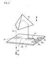
- FIG. 2 shows a similar interferometer in which linear gratings 22 and 23 are used.
- a planar optical waveguide 21a extends into or on the surface of a substrate 21, into which a beam 25 of a laser diode 24 is incident perpendicularly or almost perpendicularly. (The beam can also strike the planar optical waveguide 21a parallel to the substrate 21 in a manner not shown, then the relationships of the diffraction orders 0 and 1 to the measuring arm and to the reference arm change).
- the incident beam 25 is split into partial beams.
- the part of the 0th order falls on a measuring reflector 26 designed as a triple prism, which reflects it onto the second linear grating 23, from which it is bent and coupled into the planar optical waveguide 21a.
- the partial beam bundles of the 0th and 1st order indicated by arrows have a finite extent and the planar optical waveguide layer 21a has a finite thickness.
- the two plane waves of the 0th and 1st order interfere within this layer and form an interference fringe pattern which is detected by the detectors 28a, 28b, 28c. This effect can be created by slightly tilting the second grating with respect to the first grating.
- the interference fringes generated by one of the methods described - but not limited to these - are detected by the detectors 28a, 28b, 28c and converted into phase-shifted measurement signals.
- phase-shifting element (not shown) can also be fitted in part of the reference beam.
- a beam 35 incident from a laser diode 34 into an optical waveguide 31a is fed to a circular grating 32. There it is coupled out in the direction of a measuring reflector 36 and is reflected by the latter again onto a coupling grating 33.
- the measuring beam bundle 35 fed into the coupling grating 33 is deflected there and focused by the circular (coupling) grating 33 into an optical waveguide 31b, which is practically the continuation of the first optical waveguide 31a.
- the reference arm is formed by a partial beam 35a, which is coupled out of the optical waveguide 31a by means of a coupler 38 and is guided to a coupler 37 via an optical waveguide 31c.
- the partial beams of the measuring beam 35 interfere with the reference beam 35a in a known manner and interference signals are generated which are picked up by the detectors 38a, 38b, 38c and converted into phase-shifted electrical measuring signals.
Landscapes
- Physics & Mathematics (AREA)
- General Physics & Mathematics (AREA)
- Instruments For Measurement Of Length By Optical Means (AREA)
- Length Measuring Devices By Optical Means (AREA)
- Optical Transform (AREA)
- Vehicle Body Suspensions (AREA)
- Body Structure For Vehicles (AREA)
- Eye Examination Apparatus (AREA)
Priority Applications (7)
| Application Number | Priority Date | Filing Date | Title |
|---|---|---|---|
| EP89123897A EP0434855B1 (fr) | 1989-12-23 | 1989-12-23 | Dispositif de mesure de positions |
| AT8989123897T ATE105402T1 (de) | 1989-12-23 | 1989-12-23 | Positionsmesseinrichtung. |
| DE58907622T DE58907622D1 (de) | 1989-12-23 | 1989-12-23 | Positionsmesseinrichtung. |
| DE4007463A DE4007463A1 (de) | 1989-12-23 | 1990-03-09 | Positionsmesseinrichtung |
| DE9007809U DE9007809U1 (de) | 1989-12-23 | 1990-03-09 | Positionsmeßeinrichtung |
| JP2323360A JPH0781817B2 (ja) | 1989-12-23 | 1990-11-28 | 位置測定装置 |
| US07/629,842 US5187545A (en) | 1989-12-23 | 1990-12-19 | Integrated optical position measuring device and method with reference and measurement signals |
Applications Claiming Priority (1)
| Application Number | Priority Date | Filing Date | Title |
|---|---|---|---|
| EP89123897A EP0434855B1 (fr) | 1989-12-23 | 1989-12-23 | Dispositif de mesure de positions |
Publications (2)
| Publication Number | Publication Date |
|---|---|
| EP0434855A1 true EP0434855A1 (fr) | 1991-07-03 |
| EP0434855B1 EP0434855B1 (fr) | 1994-05-04 |
Family
ID=8202278
Family Applications (1)
| Application Number | Title | Priority Date | Filing Date |
|---|---|---|---|
| EP89123897A Expired - Lifetime EP0434855B1 (fr) | 1989-12-23 | 1989-12-23 | Dispositif de mesure de positions |
Country Status (5)
| Country | Link |
|---|---|
| US (1) | US5187545A (fr) |
| EP (1) | EP0434855B1 (fr) |
| JP (1) | JPH0781817B2 (fr) |
| AT (1) | ATE105402T1 (fr) |
| DE (2) | DE58907622D1 (fr) |
Cited By (1)
| Publication number | Priority date | Publication date | Assignee | Title |
|---|---|---|---|---|
| EP0625690A1 (fr) * | 1993-05-21 | 1994-11-23 | Dr. Johannes Heidenhain GmbH | Dispositif de mesure de position optoélectrique |
Families Citing this family (9)
| Publication number | Priority date | Publication date | Assignee | Title |
|---|---|---|---|---|
| DE59102110D1 (en) * | 1990-02-09 | 1994-08-11 | Heidenhain Gmbh Dr Johannes | Interferometer. |
| US6965709B1 (en) | 2003-05-14 | 2005-11-15 | Sandia Corporation | Fluorescent optical position sensor |
| US7049622B1 (en) | 2004-04-09 | 2006-05-23 | Sandia Corporation | Optical position sensor for determining the interface between a clear and an opaque fluid |
| DE102005025385B4 (de) * | 2005-04-20 | 2007-03-22 | Von Ardenne Anlagentechnik Gmbh | Vakuumbeschichtungsanlage zur Beschichtung flächiger Substrate mit einer Messeinrichtung zur Transmissions- oder/und Reflexionsmessung |
| US7329857B1 (en) | 2006-03-01 | 2008-02-12 | Sandia Corporation | Side-emitting fiber optic position sensor |
| US7428055B2 (en) * | 2006-10-05 | 2008-09-23 | General Electric Company | Interferometer-based real time early fouling detection system and method |
| DE102013203211A1 (de) | 2012-06-15 | 2013-12-19 | Dr. Johannes Heidenhain Gmbh | Vorrichtung zur interferentiellen Abstandsmessung |
| DE102017222864A1 (de) * | 2017-12-15 | 2019-06-19 | Robert Bosch Gmbh | Vorrichtung zur Ablenkung von Laserstrahlen |
| US11841223B2 (en) * | 2022-02-23 | 2023-12-12 | Lockheed Martin Corporation | Optical systems with controlled mirror arrangements |
Citations (1)
| Publication number | Priority date | Publication date | Assignee | Title |
|---|---|---|---|---|
| EP0276395A2 (fr) * | 1987-01-27 | 1988-08-03 | Dr. Johannes Heidenhain GmbH | Dispositif de mesure photo-électrique |
Family Cites Families (5)
| Publication number | Priority date | Publication date | Assignee | Title |
|---|---|---|---|---|
| FR2426922A1 (fr) * | 1978-05-26 | 1979-12-21 | Thomson Csf | Structure optique compacte a source integree |
| DE3630887A1 (de) * | 1986-03-26 | 1987-10-08 | Hommelwerke Gmbh | Vorrichtung zur messung kleiner laengen |
| EP0242407A2 (fr) * | 1986-03-26 | 1987-10-28 | Hommelwerke GmbH | Dispositif pour la mesure de petites longueurs |
| DE3625327C1 (de) * | 1986-07-26 | 1988-02-18 | Heidenhain Gmbh Dr Johannes | Lichtelektrische Positionsmesseinrichtung |
| FR2613826B1 (fr) * | 1987-04-07 | 1990-10-26 | Commissariat Energie Atomique | Capteur de deplacement en optique integree |
-
1989
- 1989-12-23 EP EP89123897A patent/EP0434855B1/fr not_active Expired - Lifetime
- 1989-12-23 AT AT8989123897T patent/ATE105402T1/de not_active IP Right Cessation
- 1989-12-23 DE DE58907622T patent/DE58907622D1/de not_active Expired - Fee Related
-
1990
- 1990-03-09 DE DE4007463A patent/DE4007463A1/de not_active Withdrawn
- 1990-11-28 JP JP2323360A patent/JPH0781817B2/ja not_active Expired - Lifetime
- 1990-12-19 US US07/629,842 patent/US5187545A/en not_active Expired - Lifetime
Patent Citations (1)
| Publication number | Priority date | Publication date | Assignee | Title |
|---|---|---|---|---|
| EP0276395A2 (fr) * | 1987-01-27 | 1988-08-03 | Dr. Johannes Heidenhain GmbH | Dispositif de mesure photo-électrique |
Non-Patent Citations (1)
| Title |
|---|
| JOURNAL OF LIGHTWAVE TECHNOLOGY, Band 7, Nr. 2, Februar 1989, Seiten 270-273, IEEE, New York, US; S. URA et al.: "Integrated-optic interferometer position sensor" * |
Cited By (2)
| Publication number | Priority date | Publication date | Assignee | Title |
|---|---|---|---|---|
| EP0625690A1 (fr) * | 1993-05-21 | 1994-11-23 | Dr. Johannes Heidenhain GmbH | Dispositif de mesure de position optoélectrique |
| US5500734A (en) * | 1993-05-21 | 1996-03-19 | Dr. Johannes Heidenhain Gmbh | Photoelectric position measuring system with integral optical circuit having phase shifted interference gratings |
Also Published As
| Publication number | Publication date |
|---|---|
| JPH03200002A (ja) | 1991-09-02 |
| ATE105402T1 (de) | 1994-05-15 |
| US5187545A (en) | 1993-02-16 |
| EP0434855B1 (fr) | 1994-05-04 |
| DE58907622D1 (de) | 1994-06-09 |
| DE4007463A1 (de) | 1991-06-27 |
| JPH0781817B2 (ja) | 1995-09-06 |
Similar Documents
| Publication | Publication Date | Title |
|---|---|---|
| DE69322569T2 (de) | Vorrichtung zur Erfassung von Rotationsinformationen | |
| DE69529745T3 (de) | Vorrichtung zur feststellung einer relativen bewegung | |
| EP1319170B1 (fr) | Dispositif de mesure de position | |
| EP1923673B1 (fr) | Dispositif de mesure de position | |
| EP1739395B1 (fr) | Dispositif de mesure de position | |
| DE3942385B4 (de) | Beugungsgitter-Verschiebungsmeßgerät | |
| DE102007024349A1 (de) | Optische Positionsmesseinrichtung | |
| EP0670467B1 (fr) | Interféromètre | |
| DE102010003157A1 (de) | Vorrichtung zur interferentiellen Abstandsmessung | |
| DE102008007319A1 (de) | Optische Positionsmesseinrichtung | |
| DE102013222383A1 (de) | Optische Positionsmesseinrichtung | |
| EP0425726A1 (fr) | Dispositif de mesure de position | |
| EP0625690B1 (fr) | Dispositif de mesure de position optoélectrique | |
| DE102015218539A1 (de) | Optische Positionsmesseinrichtung | |
| EP0434855B1 (fr) | Dispositif de mesure de positions | |
| DE102015203188A1 (de) | Optische Positionsmesseinrichtung | |
| DE102011076178B4 (de) | Positionsmesseinrichtung | |
| DE10058239A1 (de) | Positionsmeßeinrichtung | |
| EP0365806B1 (fr) | Dispositif de mesure de position angulaire | |
| DE102006021017A1 (de) | Positionsmesseinrichtung | |
| EP3477264B1 (fr) | Dispositif optique de mesure de position | |
| DE102011005937B4 (de) | Vorrichtung zur interferentiellen Abstandsmessung | |
| EP0590163B1 (fr) | Dispositif de mesure de longueurs ou d'angles | |
| DE19950343A1 (de) | Reflektierender Hologrammmaßstab und entsprechende optische Verschiebungsmeßvorrichtung | |
| DE102008008873A1 (de) | Positionsmesseinrichtung |
Legal Events
| Date | Code | Title | Description |
|---|---|---|---|
| PUAI | Public reference made under article 153(3) epc to a published international application that has entered the european phase |
Free format text: ORIGINAL CODE: 0009012 |
|
| 17P | Request for examination filed |
Effective date: 19900110 |
|
| AK | Designated contracting states |
Kind code of ref document: A1 Designated state(s): AT CH DE FR GB IT LI |
|
| 17Q | First examination report despatched |
Effective date: 19920721 |
|
| ITF | It: translation for a ep patent filed | ||
| GRAA | (expected) grant |
Free format text: ORIGINAL CODE: 0009210 |
|
| AK | Designated contracting states |
Kind code of ref document: B1 Designated state(s): AT CH DE FR GB IT LI |
|
| REF | Corresponds to: |
Ref document number: 105402 Country of ref document: AT Date of ref document: 19940515 Kind code of ref document: T |
|
| ET | Fr: translation filed | ||
| REF | Corresponds to: |
Ref document number: 58907622 Country of ref document: DE Date of ref document: 19940609 |
|
| GBT | Gb: translation of ep patent filed (gb section 77(6)(a)/1977) |
Effective date: 19940517 |
|
| PLBE | No opposition filed within time limit |
Free format text: ORIGINAL CODE: 0009261 |
|
| STAA | Information on the status of an ep patent application or granted ep patent |
Free format text: STATUS: NO OPPOSITION FILED WITHIN TIME LIMIT |
|
| 26N | No opposition filed | ||
| PGFP | Annual fee paid to national office [announced via postgrant information from national office to epo] |
Ref country code: GB Payment date: 20011116 Year of fee payment: 13 |
|
| PGFP | Annual fee paid to national office [announced via postgrant information from national office to epo] |
Ref country code: CH Payment date: 20011120 Year of fee payment: 13 |
|
| PGFP | Annual fee paid to national office [announced via postgrant information from national office to epo] |
Ref country code: AT Payment date: 20011203 Year of fee payment: 13 |
|
| PGFP | Annual fee paid to national office [announced via postgrant information from national office to epo] |
Ref country code: FR Payment date: 20011211 Year of fee payment: 13 |
|
| REG | Reference to a national code |
Ref country code: GB Ref legal event code: IF02 |
|
| PG25 | Lapsed in a contracting state [announced via postgrant information from national office to epo] |
Ref country code: GB Free format text: LAPSE BECAUSE OF NON-PAYMENT OF DUE FEES Effective date: 20021223 Ref country code: AT Free format text: LAPSE BECAUSE OF NON-PAYMENT OF DUE FEES Effective date: 20021223 |
|
| PG25 | Lapsed in a contracting state [announced via postgrant information from national office to epo] |
Ref country code: LI Free format text: LAPSE BECAUSE OF NON-PAYMENT OF DUE FEES Effective date: 20021231 Ref country code: CH Free format text: LAPSE BECAUSE OF NON-PAYMENT OF DUE FEES Effective date: 20021231 |
|
| GBPC | Gb: european patent ceased through non-payment of renewal fee |
Effective date: 20021223 |
|
| REG | Reference to a national code |
Ref country code: CH Ref legal event code: PL |
|
| PG25 | Lapsed in a contracting state [announced via postgrant information from national office to epo] |
Ref country code: FR Free format text: LAPSE BECAUSE OF NON-PAYMENT OF DUE FEES Effective date: 20030901 |
|
| REG | Reference to a national code |
Ref country code: FR Ref legal event code: ST |
|
| PG25 | Lapsed in a contracting state [announced via postgrant information from national office to epo] |
Ref country code: IT Free format text: LAPSE BECAUSE OF NON-PAYMENT OF DUE FEES;WARNING: LAPSES OF ITALIAN PATENTS WITH EFFECTIVE DATE BEFORE 2007 MAY HAVE OCCURRED AT ANY TIME BEFORE 2007. THE CORRECT EFFECTIVE DATE MAY BE DIFFERENT FROM THE ONE RECORDED. Effective date: 20051223 |
|
| PGFP | Annual fee paid to national office [announced via postgrant information from national office to epo] |
Ref country code: DE Payment date: 20061218 Year of fee payment: 18 |
|
| PG25 | Lapsed in a contracting state [announced via postgrant information from national office to epo] |
Ref country code: DE Free format text: LAPSE BECAUSE OF NON-PAYMENT OF DUE FEES Effective date: 20080701 |