EP0435613A2 - Dispositif de commande d'interface de bus à isolation de bus pour des réalisations de systèmes redondants - Google Patents
Dispositif de commande d'interface de bus à isolation de bus pour des réalisations de systèmes redondants Download PDFInfo
- Publication number
- EP0435613A2 EP0435613A2 EP90314140A EP90314140A EP0435613A2 EP 0435613 A2 EP0435613 A2 EP 0435613A2 EP 90314140 A EP90314140 A EP 90314140A EP 90314140 A EP90314140 A EP 90314140A EP 0435613 A2 EP0435613 A2 EP 0435613A2
- Authority
- EP
- European Patent Office
- Prior art keywords
- sensor
- channel
- bus
- computational
- channels
- Prior art date
- Legal status (The legal status is an assumption and is not a legal conclusion. Google has not performed a legal analysis and makes no representation as to the accuracy of the status listed.)
- Withdrawn
Links
Images


Classifications
-
- G—PHYSICS
- G05—CONTROLLING; REGULATING
- G05B—CONTROL OR REGULATING SYSTEMS IN GENERAL; FUNCTIONAL ELEMENTS OF SUCH SYSTEMS; MONITORING OR TESTING ARRANGEMENTS FOR SUCH SYSTEMS OR ELEMENTS
- G05B9/00—Safety arrangements
- G05B9/02—Safety arrangements electric
- G05B9/03—Safety arrangements electric with multiple-channel loop, i.e. redundant control systems
-
- G—PHYSICS
- G06—COMPUTING OR CALCULATING; COUNTING
- G06F—ELECTRIC DIGITAL DATA PROCESSING
- G06F11/00—Error detection; Error correction; Monitoring
- G06F11/07—Responding to the occurrence of a fault, e.g. fault tolerance
- G06F11/16—Error detection or correction of the data by redundancy in hardware
- G06F11/20—Error detection or correction of the data by redundancy in hardware using active fault-masking, e.g. by switching out faulty elements or by switching in spare elements
Definitions
- the present invention relates to a redundant system for processing signals from sensors and, more specifically, to a multi-bus system utilizing a bus interface controller which partitions the system in the event of a failure to maintain maximum redundancy and hence reliability.
- FIG. 1 A typical prior art redundant sensor system 10 is shown in Fig. 1.
- System 10 as shown is quad-redundant, i.e., it is composed of four identical subsystems or channels 12. Each channel 12 processes signals received from a plurality of sensors 14 relating to various measured parameters of the external environment. Cross-channel data transfers occur over bus 16, and user specific data transfers occur over bus 18.
- FIG. 2 A representative functional block diagram of an individual channel 12 in the above-described prior art system is shown in Fig. 2.
- Each channel 12 utilizes information from its own sensors in conjunction with the redundant sensor information from other channels (obtained through cross-channel transfer) to identify and isolate individual or multiple sensor or channel faults.
- An individual sensor failure simply results in a loss-of-redundancy for one sensed parameter.
- a failure of a channel's processing capability results in a loss-of-redundancy for the entire sensor set of that channel.
- the loss of a channel's sensor capability results in the loss of critical system information processing capability.
- the object of present invention is to provide a multi-bus system with partitioning capability to maintain maximum redundancy and processing capability in the event of failure of a component of the system.
- the present invention achieves the foregoing objective and overcomes the deficiencies of the above-described prior art system by providing a redundant system in which each channel is segmented into a sensor block and a computational block. These two blocks interface over busses to each other and to other channels through a bus interface controller (BIC).
- BIC bus interface controller
- the BIC coordinates the transfer of sensor data and cross-channel data to and from the computational block.
- the BIC segments the system so that cross-channel transfer is still permitted.
- the retention of the cross-channel transfer of sensor information in the event of computational block failure significantly enhances the level of redundancy and hence reliability of the system as compared to prior art systems.
- the BIC still permits the utilization of the channel's processing capabilities.
- a failure in the BIC itself can be isolated from the system through combinational logic in the sensor and computational blocks.
- the present invention is a system comprising a number of interconnected channels.
- An individual channel 30 is shown in Fig. 3 in schematic block diagram form.
- Each channel 30 is grossly functionally segmented into a sensor block 32 and a computational block 34.
- Sensor block 32 and computational block 34 each have an associated bus 36, 38, respectively.
- the interface between the two busses 36, 38 is provided by a Bus Interface Controller (BIC) 40.
- BIC 40 coordinates the transfer of information from sensor block 32 and from other channels (termed “cross-channel information transfer") to and from computational block 34.
- BIC 40 which effectively segments the system, still permits the cross-channel transfer of sensor information.
- the retention of the cross channel transfer of sensor information in the event of a computational block failure significantly enhances the level of redundancy and hence the reliability of the entire system.
- BIC 40 still permits the utilization of a channel's processing capabilities.
- sensor block 32 is shown as comprising a plurality of discrete sensors 42, which sense discrete level information relating to the external environment and convert that information into digital data. This data is sent directly to a plurality of latches 44, where it is temporarily stored.
- Sensor block 32 also includes a plurality of analog sensors 46, which generate analog data relating to parameters of the external environment. The outputs of analog sensors 46 are multiplexed to form a single analog data signal in MUX 48 and then converted into digital form in A/D converter 50.
- the digital outputs of latches 44 and A/D converter 50 are transmitted to BIC 40 over a common sensor bus 36. BIC 40 sends signals to control the operation of latches 44, MUX 48 and A/D converter 50 via control lines 54, 56, and 58, respectively.
- Fig. 4B shows the computational block of the present invention.
- a central processing unit (CPU) 60 performs computations on data received from sensor block 32 or other channels via BIC 40 over CPU bus 38. Data processed by CPU 60 is then sent back out to BIC 40 (again over CPU bus 38) for distribution to other channels.
- CPU 60 also sends control signals to BIC 40 over control and status lines 62.
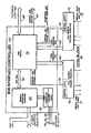
- Fig. 4C shows the details of BIC 40 and the cross channel data logic (CCDL) block 64.
- CCDL block 64 functions to convert data from parallel to serial form and vice versa, so that BIC 40 (which transmits and receives data in parallel form over busses 66, 68) can communicate with other channels over transmit serial data bus 70 and receive serial data bus 72.
- BIC 40 sends signals to control the operation of CCDL block 64 over control and status lines 74,76.
- BIC 40 contains a RAM buffer memory 78.
- RAM 78 stores data from one block of the system and transfers it out to another block under control of CPU 60 and CCDL block 64.
- RAM 78 also stores control and status signals from CPU 60 for distribution to other components of the system.
- RAM 78 interfaces with sensor block 32 via a sensor interface register 80. Data from the sensors, and signals for controlling the reading of data from the sensors, pass to and from RAM 78 to sensor interface register 80 via BIC bus 82.
- a label generator 86 coordinates the control logic, which distributes the proper control signals on the appropriate control lines 54, 56, and 58 to latches 44, MUX 48, and A/D converter 50, respectively, and the placing of labels on the sensor data as it is latched into sensor interface register 80. Each set of sensor data is thus uniquely identifiable as to the channel from which it was obtained.
- the sensor data and its associated label When the sensor data and its associated label is placed in RAM 78, it is addressable by that channel's CPU 60 directly through CPU bus 38 and is available to any other channel via CCDL transmit interface 70.
- the coordination of data transfer is accommodated by the control and status lines 74.
- Sensor data from other system channels is available to a channel's CPU 60 via the CCDL receive interface 72, bus 68, RAM 78 and CPU bus 38.
- Another channel's sensor data is uniquely decodable from RAM 78 due to the label placed on that data by the respective channel's label generator.
- Control of data receipt from the CCDL interface 72 is accommodated by the control and status lines 76.
- the CPU 60 can receive and transmit sensor, intermediate and output computational data via bus 38, RAM 78 and CCDL block 64 independent of the operational capability of the sensor block 32. Also, the reading and transmission of sensor data from sensor block 32 is independent of the operational state of the CPU 60.
- a plurality of sensors measure a parameter(s) of interest, each sensor set being associated with a separate channel.
- Each channel's CPU or processing block utilizes its own channel's sensor information and the sensor information obtained over the CCDL from other channels to determine, with high probability, the true value of the parameter being measured and to isolate sensor failures.
- the sensor values determined to be representative of the parameter to be measured are then processed by the computational block. Intermediate and final processed data is then compared between channels to isolate failed computational blocks.
- the above described architecture permits partitioning of the sensor and computational blocks of the system to permit utilization of one in the event of failure of the other.
- the system segmentation or partitioning provided by the present invention is applicable to any redundant system with subsystems divisible into two or more major functional blocks.
Landscapes
- Engineering & Computer Science (AREA)
- Physics & Mathematics (AREA)
- General Physics & Mathematics (AREA)
- Theoretical Computer Science (AREA)
- Quality & Reliability (AREA)
- General Engineering & Computer Science (AREA)
- Automation & Control Theory (AREA)
- Arrangements For Transmission Of Measured Signals (AREA)
- Hardware Redundancy (AREA)
- Debugging And Monitoring (AREA)
- Bus Control (AREA)
Applications Claiming Priority (2)
| Application Number | Priority Date | Filing Date | Title |
|---|---|---|---|
| US45832389A | 1989-12-28 | 1989-12-28 | |
| US458323 | 1999-12-10 |
Publications (2)
| Publication Number | Publication Date |
|---|---|
| EP0435613A2 true EP0435613A2 (fr) | 1991-07-03 |
| EP0435613A3 EP0435613A3 (en) | 1992-09-09 |
Family
ID=23820336
Family Applications (1)
| Application Number | Title | Priority Date | Filing Date |
|---|---|---|---|
| EP19900314140 Withdrawn EP0435613A3 (en) | 1989-12-28 | 1990-12-21 | Bus interface controller with bus isolation capability for redundant system implementations |
Country Status (5)
| Country | Link |
|---|---|
| EP (1) | EP0435613A3 (fr) |
| JP (1) | JPH04131935A (fr) |
| BR (1) | BR9006679A (fr) |
| CA (1) | CA2032423A1 (fr) |
| IL (1) | IL96648A0 (fr) |
Cited By (1)
| Publication number | Priority date | Publication date | Assignee | Title |
|---|---|---|---|---|
| DE102008062594A1 (de) | 2008-12-16 | 2010-07-01 | Diehl Aerospace Gmbh | Mehrkanal-Kontrollermodul |
Family Cites Families (1)
| Publication number | Priority date | Publication date | Assignee | Title |
|---|---|---|---|---|
| EP0110885B1 (fr) * | 1982-06-16 | 1989-09-06 | The Boeing Company | Systeme de pilote automatique de direction de vol |
-
1990
- 1990-12-13 IL IL96648A patent/IL96648A0/xx unknown
- 1990-12-17 CA CA002032423A patent/CA2032423A1/fr not_active Abandoned
- 1990-12-19 JP JP2413833A patent/JPH04131935A/ja active Pending
- 1990-12-21 BR BR909006679A patent/BR9006679A/pt unknown
- 1990-12-21 EP EP19900314140 patent/EP0435613A3/en not_active Withdrawn
Cited By (2)
| Publication number | Priority date | Publication date | Assignee | Title |
|---|---|---|---|---|
| DE102008062594A1 (de) | 2008-12-16 | 2010-07-01 | Diehl Aerospace Gmbh | Mehrkanal-Kontrollermodul |
| CN102227715A (zh) * | 2008-12-16 | 2011-10-26 | 迪尔航空航天有限公司 | 多通道控制模块 |
Also Published As
| Publication number | Publication date |
|---|---|
| EP0435613A3 (en) | 1992-09-09 |
| BR9006679A (pt) | 1991-10-01 |
| JPH04131935A (ja) | 1992-05-06 |
| IL96648A0 (en) | 1991-09-16 |
| CA2032423A1 (fr) | 1991-06-29 |
Similar Documents
| Publication | Publication Date | Title |
|---|---|---|
| US5257391A (en) | Disk controller having host interface and bus switches for selecting buffer and drive busses respectively based on configuration control signals | |
| US5768546A (en) | Method and apparatus for bi-directional transfer of data between two buses with different widths | |
| US6233635B1 (en) | Diagnostic/control system using a multi-level I2C bus | |
| US4296464A (en) | Process control system with local microprocessor control means | |
| US4101958A (en) | Apparatus and method for effecting redundant control data transfer in a digital flight control system | |
| CA1082786A (fr) | Configuration et unite de commande pour multisysteme heterogene | |
| US4970648A (en) | High performance flight recorder | |
| US4167041A (en) | Status reporting | |
| US4713757A (en) | Data management equipment for automatic flight control systems having plural digital processors | |
| CA1173929A (fr) | Systeme bus | |
| US5517514A (en) | Parity checking system with reduced usage of I/O pins | |
| EP0435613A2 (fr) | Dispositif de commande d'interface de bus à isolation de bus pour des réalisations de systèmes redondants | |
| US5404504A (en) | Trace tool for serial, optical interface | |
| GB2213934A (en) | Marine seismic data acquisition system and method in which signal errors are detected | |
| US6266748B1 (en) | Priority encoding for FIFO memory devices that interface multiple ports to a data receiving device | |
| US5603049A (en) | Bus system servicing plural module requestors with module access identification known to system user | |
| US5600786A (en) | FIFO fail-safe bus | |
| JPH0936859A (ja) | 監視情報中継方法および装置 | |
| EP0658844B1 (fr) | Unité centrale de traitement avec unités doubles de traitement de base et vérification utilisant la comparaison des résultats accumulés | |
| EP0076408B1 (fr) | Méthode d'adressage fonctionnelle pour un bus de données multiplexées | |
| RU2080653C1 (ru) | Устройство для сбора, обработки и пакетной передачи результатов измерения параметров физической среды | |
| JP3095060B2 (ja) | Atmスイッチ装置 | |
| GB2084770A (en) | Data exchange between a pair of computers operating according to the masterslave principle and a support computer | |
| JPH0415648B2 (fr) | ||
| GB2087689A (en) | Transit exchanges of time division telecommunication systems |
Legal Events
| Date | Code | Title | Description |
|---|---|---|---|
| PUAI | Public reference made under article 153(3) epc to a published international application that has entered the european phase |
Free format text: ORIGINAL CODE: 0009012 |
|
| AK | Designated contracting states |
Kind code of ref document: A2 Designated state(s): AT BE CH DE DK ES FR GB GR IT LI LU NL SE |
|
| PUAL | Search report despatched |
Free format text: ORIGINAL CODE: 0009013 |
|
| AK | Designated contracting states |
Kind code of ref document: A3 Designated state(s): AT BE CH DE DK ES FR GB GR IT LI LU NL SE |
|
| STAA | Information on the status of an ep patent application or granted ep patent |
Free format text: STATUS: THE APPLICATION IS DEEMED TO BE WITHDRAWN |
|
| 18D | Application deemed to be withdrawn |
Effective date: 19930310 |