EP0435904B1 - Method and apparatus for coating paper and the like - Google Patents
Method and apparatus for coating paper and the like Download PDFInfo
- Publication number
- EP0435904B1 EP0435904B1 EP89910449A EP89910449A EP0435904B1 EP 0435904 B1 EP0435904 B1 EP 0435904B1 EP 89910449 A EP89910449 A EP 89910449A EP 89910449 A EP89910449 A EP 89910449A EP 0435904 B1 EP0435904 B1 EP 0435904B1
- Authority
- EP
- European Patent Office
- Prior art keywords
- fog
- substrate
- slurry
- nozzle
- providing
- Prior art date
- Legal status (The legal status is an assumption and is not a legal conclusion. Google has not performed a legal analysis and makes no representation as to the accuracy of the status listed.)
- Expired - Lifetime
Links
Images
Classifications
-
- B—PERFORMING OPERATIONS; TRANSPORTING
- B05—SPRAYING OR ATOMISING IN GENERAL; APPLYING FLUENT MATERIALS TO SURFACES, IN GENERAL
- B05B—SPRAYING APPARATUS; ATOMISING APPARATUS; NOZZLES
- B05B5/00—Electrostatic spraying apparatus; Spraying apparatus with means for charging the spray electrically; Apparatus for spraying liquids or other fluent materials by other electric means
- B05B5/08—Plant for applying liquids or other fluent materials to objects
-
- D—TEXTILES; PAPER
- D21—PAPER-MAKING; PRODUCTION OF CELLULOSE
- D21H—PULP COMPOSITIONS; PREPARATION THEREOF NOT COVERED BY SUBCLASSES D21C OR D21D; IMPREGNATING OR COATING OF PAPER; TREATMENT OF FINISHED PAPER NOT COVERED BY CLASS B31 OR SUBCLASS D21G; PAPER NOT OTHERWISE PROVIDED FOR
- D21H23/00—Processes or apparatus for adding material to the pulp or to the paper
- D21H23/02—Processes or apparatus for adding material to the pulp or to the paper characterised by the manner in which substances are added
- D21H23/22—Addition to the formed paper
- D21H23/50—Spraying or projecting
Definitions
- the slurry is removed from the tank 10 by a pump 14, the pump 14 having its discharge connected to a line 15 for feeding a nozzle 16.
- the nozzle 16 breaks up the slurry from the tank 10 so that the slurry becomes a spray having very small particle size, or a fog.
- the material will be referred to as a fog, and it should be understood that this term includes a range of forms from a very small particle aerosol to a relatively small particle spray.
Landscapes
- Application Of Or Painting With Fluid Materials (AREA)
- Paper (AREA)
Abstract
Description
- It is well known that paper, paper board and other such materials are coated with various substances to change the color, the surface texture or the like. This coating sometimes includes a dyeing material to change the color, and often includes clay or other relatively heavy materials to fill the somewhat porous surface of a paper or paperboard to yield a smooth surface.
- As is well known in the art, the manufacture of paper is a generally continuous process wherein the web has an extremely high water content, the water content being gradually reduced until the web is ultimately dried. Because of the nature of the method and apparatus for applying coatings, one is generally very limited in the selection of the stage of paper production at which the coatings are applied. Specifically, clay and the like are usually placed on the surface and scraped to the desired thickness by a roller, a doctor blade, or a similar mechanical means. This requires that the paper substrate be sufficiently strong to withstand mechanical forces as the coating is spread uniformly over the surface. There has been some effort at spraying coating materials on paper-like substrates, but the coatings have never been successfully applied using a spraying technique.
- This invention relates generally to the coating of substrates, and is more particularly concerned with a method and apparatus for coating a substrate without mechanical contact with the substrate as defined in
claims 1, 8 and 10. - The present invention includes the preparation of a slurry to be used as the coating mixture, and the generation of a fog from the slurry. The fog may be mixed with fogs containing other coating materials if desired; then, the fog containing the final materials to be applied to the substrate is directed against the substrate. In the preferred embodiment, the fog and the substrate may contain static charges that assist both in contact and in retaining of the fog on the substrate, though success has been achieved without the use of the static charges.
- The fog may be generated in many ways, including through the use of generally conventional spray nozzles. Another embodiment of the invention utilizes ultrasonic energy to create the fog, and perhaps by means of an ultrasonic nozzle of the type well known in the art.
- These and other features and advantages of the present invention will become apparent from consideration of the following specification when taken in conjunction with the accompanying drawing in which:
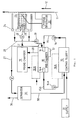
The single figure is a schematic, flow diagram illustrating a method and apparatus for coating paper in accordance with the present invention. - Referring now more particularly to the drawings, and to those embodiments of the invention here presented by way of illustration, it will be seen that there is a tank designated at 10 which contains a slurry to be coated on the substrate designated at 11. It will be noticed that the
substrate 11 is shown extending vertically, and moving upwardly as indicated by thearrow 12. This particular orientation of thesubstrate 11 is by way of illustration only, and those skilled in the art will realize that the substrate may move in any direction. While it is possible that a substrate having sufficient integrity can be moved vertically, and coated while moving vertically, the substrate also may be moving generally horizontally, for example on the wire of a Fourdrinier machine. - Returning then to the
tank 10, it will be seen that the slurry is removed from thetank 10 by apump 14, thepump 14 having its discharge connected to aline 15 for feeding anozzle 16. Thenozzle 16 breaks up the slurry from thetank 10 so that the slurry becomes a spray having very small particle size, or a fog. In the present application, the material will be referred to as a fog, and it should be understood that this term includes a range of forms from a very small particle aerosol to a relatively small particle spray. - The
nozzle 16 may comprise many specific pieces of hardware. It is possible that, by using apump 14 having sufficient pressure, thenozzle 16 may in fact be a fluid type nozzle wherein the nozzle will break up a fluid that flows therethrough to produce a fine-particle spray, or a nozzle wherein gas under pressure breaks up the liquid and mixes therewith to form the fog. It is also possible to use an ultrasonic nozzle, generally of the type disclosed in the U.S. Patent to Berger et al., No. 4,352,459. Ultrasonic nozzles are well known in the art, and those skilled in the art will understand without further explanation. - One further form that the
nozzle 16 may take is a transducer located at the bottom of thetank 18. It will be noted that thetank 18 is illustrated as having some slurry in the bottom thereof, with the fog in the upper portion of thetank 18. By placing atransducer 17 at the bottom of thetank 18, ultrasonic energy can break up the slurry into fine particles to produce the desired fog above the liquid, additional fog being generated as fog is removed for use. - It will be noted that the fog from the
tank 18 is directed to amixing chamber 19, and further that there is a second tank designated at 18A, which also has its output directed to themixing chamber 19. If desired, one might have two or more tanks such as thetanks 18 and 18A, each of thetanks 18 and 18A containing a different slurry and different fog so that two or more materials can be coated on asubstrate 11 simultaneously. In the event two or more slurries and fogs are used, the plural tanks such as 18 and 18A can be utilized, the output of all being directed to themixing chamber 19 where the fogs are intermixed to the point of substantial homogeniety. In the event only one tank such as thetank 18 is to be used, themixing chamber 19 may be omitted, and theoutput 20 from thetank 18 can be connected directly to theoutput 21 of themixing chamber 19. - Another means for providing two different materials for coating the
substrate 11 is to provide two or more of the tanks such as thetank 10. In the drawings, a second tank 10A is shown, and apump 14A moves the material from the tank 10A and feeds the material through aline 15A to a nozzle 16A in thetank 18. It will therefore be understood that two different fogs are generated within thetank 18 by thenozzles 16 and 16A. The mixed fogs will then be directed to themixing chamber 19, or directly to theapplication nozzle 24. - From the
mixing chamber 19, the output at 21 is directed through avalve 22, then to the application nozzle generally indicated at 24. Those skilled in the art will be aware that a valve arrangement is commonly used in adjusting pressure across the web of paper, such valve arrangements being computer controlled in a plurality of sections to equalize the pressure across the web. Thevalve 22 here illustrated is expected to take the form of that prior art arrangement, the object being to adjust the volume of material directed to thesubstrate 11. - The present invention also provides injection means 23 for injecting air or other gas into the stream of fog. The injection means 23 are shown to be located adjacent to the walls of the
application nozzle 24, and in this position a curtain of gas is placed along the walls to prevent the attachment of droplets on the walls. - The injection means 23, however, can replace the
valve 22. A plurality ofgas injectors 23 can be placed across the nozzle, or a conduit leading to the nozzle. These gas injectors can be computer controlled as with theprior art valve 22; but, the quantity of material will be varied by injecting gas to dilute the material. It will also be understood that thegas injectors 23 can be used alone, or in conjuction with a conventional valve such as thevalve 22. The curtain can prevent formation of droplets on the walls, while thevalve 22 can be used as the control. - In looking at the
application nozzle 24, it should be understood that the fog is carried to theapplication nozzle 24 by the air flow produced by a fan, or centrifugal blower, 29. The output of theblower 29 is directed to thetank 18 which contains a supply of fog. A current is therefore established through theline 21 and through thevalve 22, then to theapplication nozzle 24 and onto thesubstrate 11. Thenozzle 24 includes acentral application area 25 which receives the fog and directs the fog towards thesubstrate 11, and the fog will tend to move in a straight line and engage thesubstrate 11. - In the event some of the fog fails to engage the
substrate 11 and/or fails to adhere thereto, thenozzle 24 includes areturn chamber 26. Thechamber 26 is connected through theline 28 to the suction side of theblower 29 so thereturn chamber 26 is at a lower pressure and will somewhat scavenge the area of theapplication nozzle 24. Also of course, thereturn chamber 26 acts as the intake for theblower 29. Fluid therefore flows through theline 28, through theblower 29, through thetank 18, thence through theline 20, thechamber 19, and theline 21. Thevalve 22 will adjust the flow and allow the desired fog to enter theapplication chamber 25 of thenozzle 24. - Since the flow to the
application nozzle 24 may be varied, it is desirable to utilize avariable speed blower 29 in an effort to match the flow through theblower 29 to the flow to thenozzle 24. Even so, there may be times when there is excess volume at the high pressure side of theblower 29; therefore, ableed line 27 will allow the excess to be directed to aseparator 35. - To assist in causing the fog to attach to the
substrate 11, it is contemplated that a static electric charge will be utilized on the fog and on thesubstrate 11. Those skilled in the art will readily understand that thesubstrate 11 can be charged, and that the fog can be charged by means of a grating or the like. For purposes of illustration, a charge generator is indicated at 30, there being only one charge generator shown. Nevertheless, it will be understood that one charge (e.g. a negative) can be generated and placed on thesubstrate 11 while the opposite charge (e.g. a positive) can be placed on the fog. These opposite charges will cause the fog to be attracted to thesubstrate 11 and stick thereto. - An important feature of the present invention is the application of the fog-containing coating material to a
substrate 11 at low pressure and without mechanical manipulation or the like. This allows the system of the present invention to be utilized for coating paper anywhere along the paper production line, from the first de-watering stage until the paper has been completely dried. If desired, the paper can be manufactured and rolled up, and the rolls can be transported to another location, unrolled and then coated using the system of the present invention. - Returning briefly to the drawing, it will be seen that there is a supply of material designated at 31. This supply of material can be a larger tank, mixing means or the like to supply the coating slurry in the
tank 10. Those skilled in the art will understand that any means for providing the slurry in thetank 10 is a reasonable equivalent of thesupply 31 shown. - Looking again at the
separator 35, theseparator 35 may include any conventional filter or the like, the object of theseparator 35 being to separate the gas from the liquid portion of the excess fog from theblower 29. When the gas and liquid are separated, the gas is simply discharged to atmosphere at 36, and the liquid is returned through theline 38 to thetank 10 for reuse. If it is determined that the gases discharged at 36 contain improper contaminants, some further removal of material may be necessary before the gas is discharged to the atmosphere. - It will therefore be seen that the present invention provides an extremely simple method and apparatus for coating substrates. Since the slurry to be coated on the substrate is transformed into a fog, and the fog is applied at very low pressure, it will be understood that the substrate will never be harmed, even when the substrate is largely water. The use of the electrostatic charge will assure appropriate coating of the substrate and adherence thereto until the substrate is completely dried. Further, in view of the coating technique, it will be understood that any conventional drying technique is appropriate so that infrared lamps or the like can be utilized to dry the coating on paper or board.
- It will of course be understood by those skilled in the art that the particular embodiments of the invention here presented are by way of illustration only, and are meant to be in no way restrictive; therefore, numerous changes and modifications may be made, and the full use of equivalents reported to, without departing from the invention as outlined in the appended claims.
Claims (15)
- A method for coating a paper, board, or the like substrate wherein said substrate moves continuously along a path, said method including the steps of providing a slurry containing the material to be coated on said substrate and including a solid particulate material, breaking up said slurry into small particles for producing a fog containing said material to be coated on said substrate, said fog including said solid particulate material in suspension in gas, providing sufficient gas flow to maintain said solid particulate material in suspension, and directing said fog with said solid particulate material towards said substrate for adherence of said solid particulate material to said substrate.
- A method as claimed in claim 1, wherein the step of breaking up said slurry into small particles comprises the steps of feeding said slurry to a nozzle, and utilizing said nozzle to break up said slurry, and placing the resulting fog into a fog chamber.
- A method as claimed in claim 1, wherein the said step of directing said fog towards said substrate includes the steps of placing an application nozzle adjacent to said substrate, and directing said fog to enter said application nozzle, and wherein the said step of providing sufficient gas flow to maintain said particulate material in suspension also constitutes providing a positive force for urging said fog towards said substrate.
- A method as claimed in claim 2, said fog chamber containing some of said slurry, and means for breaking up said some of said slurry for creating a fog within said fog chamber.
- A method as claimed in claim 3, wherein said positive force for urging said fog towards said substrate includes electrostatic charges for causing said fog to be attracted to said substrate.
- A method as claimed in claim 3, wherein said positive force includes a fluid current entraining said fog, and including the step of directing said fluid current towards said substrate.
- A method as claimed in claim 3, and further including the step of providing a vacuum adjacent to said application nozzle for picking up excess fog.
- A method for coating a paper-like substrate wherein said substrate moves continuously along a path, said method including the steps of providing a slurry containing the material to be coated on said substrate, breaking up said slurry into small particles for producing a fog containing said material to be coated on said substrate, and directing said fog towards said substrate for adherence to said substrate, wherein the said step of directing said fog towards said substrate includes the steps of placing an application nozzle adjacent to said substrate, and providing a positive force for urging said fog towards said substrate, and further including the steps of providing a plurality of slurries for coating said substrate, creating a fog from each slurry of said plurality of slurries, mixing all the fogs created, and directing the resulting mixture of fogs to said application nozzle.
- A method as claimed in claim 3, and further including the step of injecting a gas into the fog as the fog enters the application nozzle for diluting said fog.
- Paper coating apparatus for coating a continuously moving substrate, said apparatus including means for providing a slurry containing solid material to be coated onto said substrate, means for, by gas under pressure, breaking up said slurry into fine particles for creating a fog containing said solid material to be coated onto said substrate, application means for applying said fog to said substrate, said application means being adjacent to and spaced from said substrate, and means for providing a current of gas for entraining said fog and carrying said fog through said application means.
- Paper coating apparatus as claimed in claim 10, said means for breaking up said slurry including a fog chamber, and nozzle means in said fog chamber for breaking up said slurry.
- Paper coating apparatus as claimed in claim 11, said application means comprising an application nozzle having an application area, and further including a vacuum chamber adjacent to said application area for picking up excess fog in the vicinity of said substrate.
- Paper coating apparatus as claimed in claim 12, and further including charge generating means for generating electrostatic charges, means for placing one electrostatic charge on said substrate, and means for placing the opposite electrostatic charge on said fog when said fog is said in application nozzle.
- Paper coating apparatus as claimed in claim 13, and further including means for controlling the quantity of fog directed to said application means.
- Paper coating apparatus as claimed in claim 14, and including a plurality of said fog chambers, and a plurality of said means for providing a slurry containing the material to be coated, the arrangement being such that a fog can be created from each of plurality of materials to be coated onto said substrate, and further including a mixing chamber for receiving a plurality of fogs for mixing the fogs and directing the mixture to said nozzle.
Applications Claiming Priority (2)
| Application Number | Priority Date | Filing Date | Title |
|---|---|---|---|
| US07/248,177 US4944960A (en) | 1988-09-23 | 1988-09-23 | Method and apparatus for coating paper and the like |
| US248177 | 1988-09-23 |
Publications (2)
| Publication Number | Publication Date |
|---|---|
| EP0435904A1 EP0435904A1 (en) | 1991-07-10 |
| EP0435904B1 true EP0435904B1 (en) | 1994-03-02 |
Family
ID=22938029
Family Applications (1)
| Application Number | Title | Priority Date | Filing Date |
|---|---|---|---|
| EP89910449A Expired - Lifetime EP0435904B1 (en) | 1988-09-23 | 1989-09-22 | Method and apparatus for coating paper and the like |
Country Status (7)
| Country | Link |
|---|---|
| US (1) | US4944960A (en) |
| EP (1) | EP0435904B1 (en) |
| AU (1) | AU4313589A (en) |
| CA (1) | CA1327487C (en) |
| DE (1) | DE68913551T2 (en) |
| NZ (1) | NZ230741A (en) |
| WO (1) | WO1990003225A1 (en) |
Cited By (2)
| Publication number | Priority date | Publication date | Assignee | Title |
|---|---|---|---|---|
| EP0955408A2 (en) | 1998-05-07 | 1999-11-10 | Voith Sulzer Papiertechnik Patent GmbH | Process and apparatus for applying a coating onto a moving basis |
| DE102009009862A1 (en) | 2009-02-20 | 2010-08-26 | V.I.B. Systems Gmbh | Method and installation for applying a suspension to a material web |
Families Citing this family (30)
| Publication number | Priority date | Publication date | Assignee | Title |
|---|---|---|---|---|
| DE3925539A1 (en) * | 1989-08-02 | 1991-02-07 | Hoechst Ag | METHOD AND DEVICE FOR COATING A LAYER |
| JPH03244528A (en) * | 1989-09-28 | 1991-10-31 | Three D Syst Inc | Device and method forming substantially flat and solid face for processing planograph |
| FI90575C (en) * | 1992-01-30 | 1994-02-25 | Valmet Paper Machinery Inc | The device in a glue press |
| DE69323438T2 (en) | 1992-11-06 | 1999-06-24 | Robert Christchurch Neuseeland Donnelly | METHOD AND DEVICE FOR COATING PAPER AND THE LIKE |
| ATE152193T1 (en) * | 1993-09-14 | 1997-05-15 | Voith Sulzer Papiermasch Gmbh | METHOD AND DEVICE FOR COATING A RUNNING WEB |
| DE4344552A1 (en) * | 1993-12-24 | 1995-06-29 | Giesecke & Devrient Gmbh | Method and device for equipping securities with authenticity features |
| US5622599A (en) * | 1994-06-28 | 1997-04-22 | Sproule; Barry | Method and apparatus for coating pulp products |
| FI97247C (en) * | 1994-07-01 | 1998-07-21 | Valmet Paper Machinery Inc | Spray coating method and apparatus |
| US5849321A (en) * | 1994-07-01 | 1998-12-15 | Valmet Corporation | Method and apparatus for spray-coating a paper or board web |
| FI108061B (en) * | 1995-10-05 | 2001-11-15 | Metso Paper Inc | Method for coating a paper or cardboard web |
| US5916640A (en) * | 1996-09-06 | 1999-06-29 | Msp Corporation | Method and apparatus for controlled particle deposition on surfaces |
| FI108063B (en) * | 1997-09-09 | 2001-11-15 | Runtech Systems Oy | Method and apparatus for treating a material web |
| DE19755625A1 (en) * | 1997-12-15 | 1999-07-01 | Jagenberg Papiertech Gmbh | Slot nozzle for coating material webs, in particular paper or cardboard webs with pigment coating ink |
| US6344109B1 (en) | 1998-12-18 | 2002-02-05 | Bki Holding Corporation | Softened comminution pulp |
| SE0100851L (en) * | 2001-03-13 | 2002-09-14 | Stora Enso Oyj | Method of making paper or paperboard and a paper or paperboard made thereby |
| FI115314B (en) * | 2001-03-13 | 2005-04-15 | Metso Paper Inc | Apparatus for processing paper or cardboard |
| DE10120818A1 (en) * | 2001-04-27 | 2002-10-31 | Giesecke & Devrient Gmbh | Method and device for introducing feature substances into a paper web |
| US6918993B2 (en) * | 2002-07-10 | 2005-07-19 | Kimberly-Clark Worldwide, Inc. | Multi-ply wiping products made according to a low temperature delamination process |
| US6991706B2 (en) * | 2003-09-02 | 2006-01-31 | Kimberly-Clark Worldwide, Inc. | Clothlike pattern densified web |
| KR101087339B1 (en) * | 2003-09-02 | 2011-11-25 | 킴벌리-클라크 월드와이드, 인크. | Low odor binder curable at room temperature |
| US20050045293A1 (en) | 2003-09-02 | 2005-03-03 | Hermans Michael Alan | Paper sheet having high absorbent capacity and delayed wet-out |
| US7189307B2 (en) * | 2003-09-02 | 2007-03-13 | Kimberly-Clark Worldwide, Inc. | Low odor binders curable at room temperature |
| US7297231B2 (en) | 2004-07-15 | 2007-11-20 | Kimberly-Clark Worldwide, Inc. | Binders curable at room temperature with low blocking |
| WO2007003059A1 (en) * | 2005-07-04 | 2007-01-11 | H. U. Jakob Papiertechnik Ag | Device for spraying different media at great speed |
| US20070190261A1 (en) * | 2006-02-10 | 2007-08-16 | Ronald Darnell | Overspray apparatus and process |
| US8789492B2 (en) * | 2008-07-15 | 2014-07-29 | Awi Licensing Company | Coating apparatus and method |
| AT509594B1 (en) * | 2010-09-23 | 2011-10-15 | Inova Lisec Technologiezentrum | PROCESS FOR COATING |
| CN104069968B (en) * | 2013-03-28 | 2017-01-04 | 株式会社Enjet | Spray nozzle and the application system of this spray nozzle of use |
| KR101545049B1 (en) * | 2013-09-13 | 2015-08-17 | 엔젯 주식회사 | System for coating using spray nozzle |
| DE102014100605A1 (en) | 2014-01-21 | 2015-07-23 | Paperchine Gmbh | Nozzle arrangement with self-cleaning front surface |
Family Cites Families (10)
| Publication number | Priority date | Publication date | Assignee | Title |
|---|---|---|---|---|
| US2684656A (en) * | 1949-07-30 | 1954-07-27 | Ransburg Electro Coating Corp | Electrostatic coating apparatus |
| US3074697A (en) * | 1958-08-22 | 1963-01-22 | Norgren Co C A | Apparatus for generating an aerosol |
| US3536580A (en) * | 1967-10-13 | 1970-10-27 | Ransburg Electro Coating Corp | Paper making methods and apparatus involving electrostatic spray coating |
| US3868925A (en) * | 1970-08-14 | 1975-03-04 | Nat Steel Corp | Electrostatic coating of metal powder on metal strip |
| US4046074A (en) * | 1976-02-02 | 1977-09-06 | International Business Machines Corporation | Non-impact printing system |
| US4170193A (en) * | 1976-04-16 | 1979-10-09 | Ball Corporation | Apparatus for applying lubricating materials to metallic substrates |
| US4558657A (en) * | 1980-07-11 | 1985-12-17 | Midwest Automation, Inc. | Spraying apparatus |
| US4752496A (en) * | 1986-05-27 | 1988-06-21 | Qmax Technology Group, Inc. | Method of applying cosmetics to a substrate and article |
| DE3631270A1 (en) * | 1986-09-13 | 1988-03-24 | Kopperschmidt Mueller & Co | DEVICE FOR SPRAY COATING WORKPIECES |
| DE285794T1 (en) * | 1987-04-01 | 1989-01-26 | Polaroid Corp., Cambridge, Mass. | METHOD AND DEVICE FOR APPLYING ULTRADUEN LAYERS TO A SUBSTRATE. |
-
1988
- 1988-09-23 US US07/248,177 patent/US4944960A/en not_active Expired - Lifetime
-
1989
- 1989-09-22 CA CA000612693A patent/CA1327487C/en not_active Expired - Lifetime
- 1989-09-22 NZ NZ230741A patent/NZ230741A/en unknown
- 1989-09-22 DE DE68913551T patent/DE68913551T2/en not_active Expired - Lifetime
- 1989-09-22 AU AU43135/89A patent/AU4313589A/en not_active Abandoned
- 1989-09-22 EP EP89910449A patent/EP0435904B1/en not_active Expired - Lifetime
- 1989-09-22 WO PCT/FI1989/000177 patent/WO1990003225A1/en not_active Ceased
Cited By (6)
| Publication number | Priority date | Publication date | Assignee | Title |
|---|---|---|---|---|
| EP0955408A2 (en) | 1998-05-07 | 1999-11-10 | Voith Sulzer Papiertechnik Patent GmbH | Process and apparatus for applying a coating onto a moving basis |
| DE19820432A1 (en) * | 1998-05-07 | 1999-11-11 | Voith Sulzer Papiertech Patent | Method and device for applying an application medium to a running surface |
| US6248407B1 (en) | 1998-05-07 | 2001-06-19 | Voith Sulzer Papiertechnik Gmbh | Method for applying a coating medium onto a moving surface |
| US6503325B1 (en) | 1998-05-07 | 2003-01-07 | Voith Sulzer Papiertechnik Patent Gmbh | Device and method for applying a coating medium onto a moving surface |
| DE102009009862A1 (en) | 2009-02-20 | 2010-08-26 | V.I.B. Systems Gmbh | Method and installation for applying a suspension to a material web |
| DE102009009862B4 (en) * | 2009-02-20 | 2013-10-10 | Paperchine Gmbh | Method and installation for applying a suspension to a material web |
Also Published As
| Publication number | Publication date |
|---|---|
| DE68913551D1 (en) | 1994-04-07 |
| DE68913551T2 (en) | 1994-07-07 |
| AU4313589A (en) | 1990-04-18 |
| WO1990003225A1 (en) | 1990-04-05 |
| NZ230741A (en) | 1992-04-28 |
| EP0435904A1 (en) | 1991-07-10 |
| CA1327487C (en) | 1994-03-08 |
| US4944960A (en) | 1990-07-31 |
Similar Documents
| Publication | Publication Date | Title |
|---|---|---|
| EP0435904B1 (en) | Method and apparatus for coating paper and the like | |
| EP0682571B1 (en) | Method and apparatus for coating paper or the like | |
| KR100897007B1 (en) | Liquid spray unit, method for spraying liquid using it, and chemical | |
| US3071822A (en) | Method and apparatus for forming a mat | |
| US10240865B2 (en) | Non-thermal drying systems and methods using vacuum throttle flash generators and processing vessels | |
| EP2772584A1 (en) | Method and arrangement for a fiber web production line | |
| US6620243B1 (en) | Fluidized bed powder handling and coating apparatus and methods | |
| JP2000517243A (en) | Method and apparatus for controlled particle deposition on a surface | |
| JPH11333341A (en) | Method and device for applying coating agent to moving substrate | |
| US5435945A (en) | Method and apparatus for generating sulphur seed particles for sulphur granule production | |
| GB794725A (en) | A method and apparatus for producing webs or sheets of fibrous material | |
| US5849321A (en) | Method and apparatus for spray-coating a paper or board web | |
| KR19990073019A (en) | Powder Cross-Feed Auger and Method | |
| US5520889A (en) | Method for controlling the discharge of granules from a nozzle onto a coated sheet | |
| JPH10156249A5 (en) | ||
| CA2315465C (en) | Electrostatic flocking chamber for forming electrostatic flocking apparatus | |
| US6197368B1 (en) | Particulate coating apparatus and method | |
| FI97072B (en) | Method and device for coating paper or the like | |
| EP1053981A2 (en) | Fluid spray apparatus and method for smooth surface gypsum fiberboard panels | |
| US4051576A (en) | Apparatus for aerodynamically forming a fibrous sheet material | |
| US4635585A (en) | System for spray coating substrates | |
| WO2003020433A1 (en) | Coating device for processing a liquid into fine mist and spraying the fine mist towards a workpiece | |
| CN1198965A (en) | Method and device for coating web-like sheet formation | |
| CN1260012C (en) | Spraying method with controllable spraying amount | |
| EP0813451B1 (en) | Method and apparatus for fabricating a particle-coated substrate |
Legal Events
| Date | Code | Title | Description |
|---|---|---|---|
| PUAI | Public reference made under article 153(3) epc to a published international application that has entered the european phase |
Free format text: ORIGINAL CODE: 0009012 |
|
| 17P | Request for examination filed |
Effective date: 19910321 |
|
| AK | Designated contracting states |
Kind code of ref document: A1 Designated state(s): DE FR GB IT SE |
|
| 17Q | First examination report despatched |
Effective date: 19930222 |
|
| GRAA | (expected) grant |
Free format text: ORIGINAL CODE: 0009210 |
|
| AK | Designated contracting states |
Kind code of ref document: B1 Designated state(s): DE FR GB IT SE |
|
| ITF | It: translation for a ep patent filed | ||
| REF | Corresponds to: |
Ref document number: 68913551 Country of ref document: DE Date of ref document: 19940407 |
|
| ET | Fr: translation filed | ||
| PLBE | No opposition filed within time limit |
Free format text: ORIGINAL CODE: 0009261 |
|
| STAA | Information on the status of an ep patent application or granted ep patent |
Free format text: STATUS: NO OPPOSITION FILED WITHIN TIME LIMIT |
|
| EAL | Se: european patent in force in sweden |
Ref document number: 89910449.1 |
|
| 26N | No opposition filed | ||
| REG | Reference to a national code |
Ref country code: GB Ref legal event code: IF02 |
|
| PGFP | Annual fee paid to national office [announced via postgrant information from national office to epo] |
Ref country code: GB Payment date: 20070918 Year of fee payment: 19 |
|
| PGFP | Annual fee paid to national office [announced via postgrant information from national office to epo] |
Ref country code: IT Payment date: 20070915 Year of fee payment: 19 Ref country code: SE Payment date: 20070911 Year of fee payment: 19 |
|
| PGFP | Annual fee paid to national office [announced via postgrant information from national office to epo] |
Ref country code: FR Payment date: 20070928 Year of fee payment: 19 |
|
| PGFP | Annual fee paid to national office [announced via postgrant information from national office to epo] |
Ref country code: DE Payment date: 20080917 Year of fee payment: 20 |
|
| GBPC | Gb: european patent ceased through non-payment of renewal fee |
Effective date: 20080922 |
|
| REG | Reference to a national code |
Ref country code: FR Ref legal event code: ST Effective date: 20090529 |
|
| PG25 | Lapsed in a contracting state [announced via postgrant information from national office to epo] |
Ref country code: IT Free format text: LAPSE BECAUSE OF NON-PAYMENT OF DUE FEES Effective date: 20080922 |
|
| PG25 | Lapsed in a contracting state [announced via postgrant information from national office to epo] |
Ref country code: FR Free format text: LAPSE BECAUSE OF NON-PAYMENT OF DUE FEES Effective date: 20080930 |
|
| PG25 | Lapsed in a contracting state [announced via postgrant information from national office to epo] |
Ref country code: GB Free format text: LAPSE BECAUSE OF NON-PAYMENT OF DUE FEES Effective date: 20080922 |
|
| PG25 | Lapsed in a contracting state [announced via postgrant information from national office to epo] |
Ref country code: SE Free format text: LAPSE BECAUSE OF NON-PAYMENT OF DUE FEES Effective date: 20080923 |